


The document discusses the concept of polarization of light waves, defining unpolarized and polarized light, and detailing types of polarization such as linear, circular, and elliptical. It explains how light can be polarized through reflection, refraction, scattering, and double refraction in birefringent crystals, including the roles of o-ray and e-ray. Additionally, it elaborates on the applications of Brewster's Law and the use of retarders like quarter wave and half wave plates to manipulate the polarization of light.
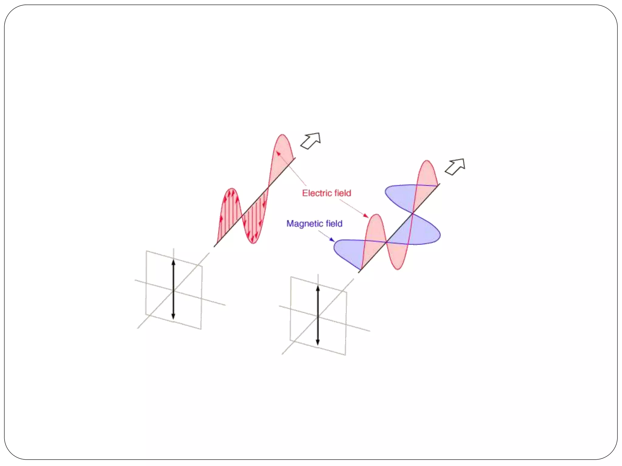
Introduction to polarization; light as a transverse electromagnetic wave; distinction between unpolarized and polarized light.
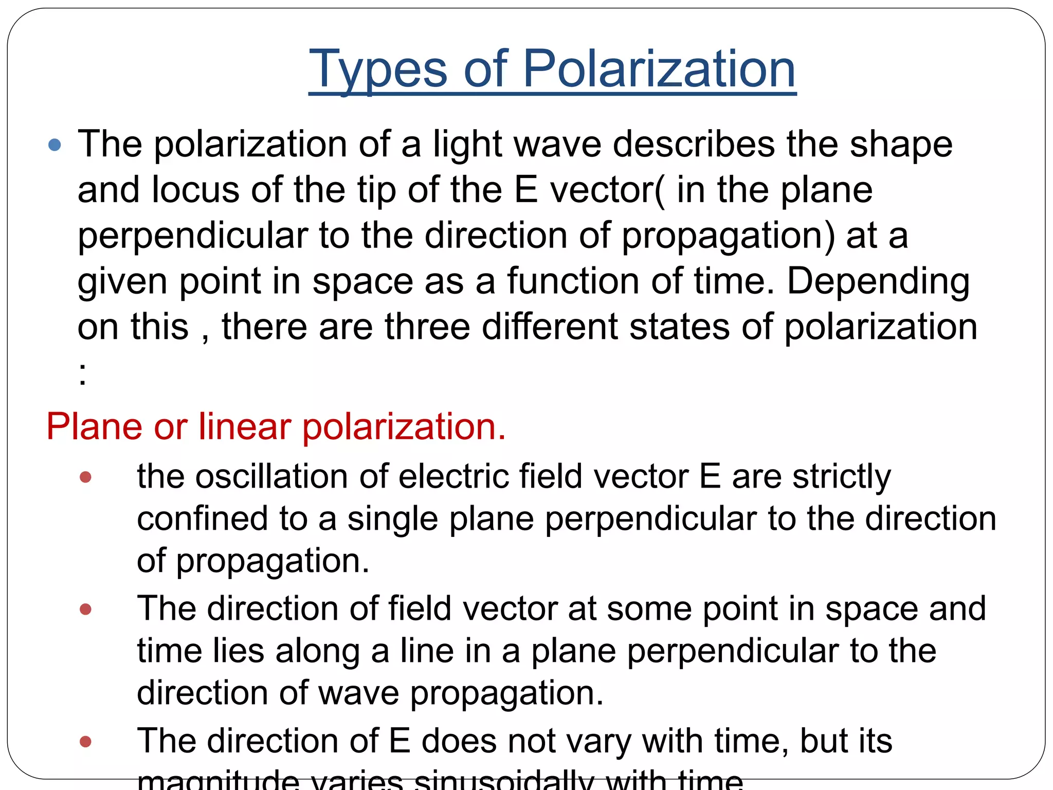
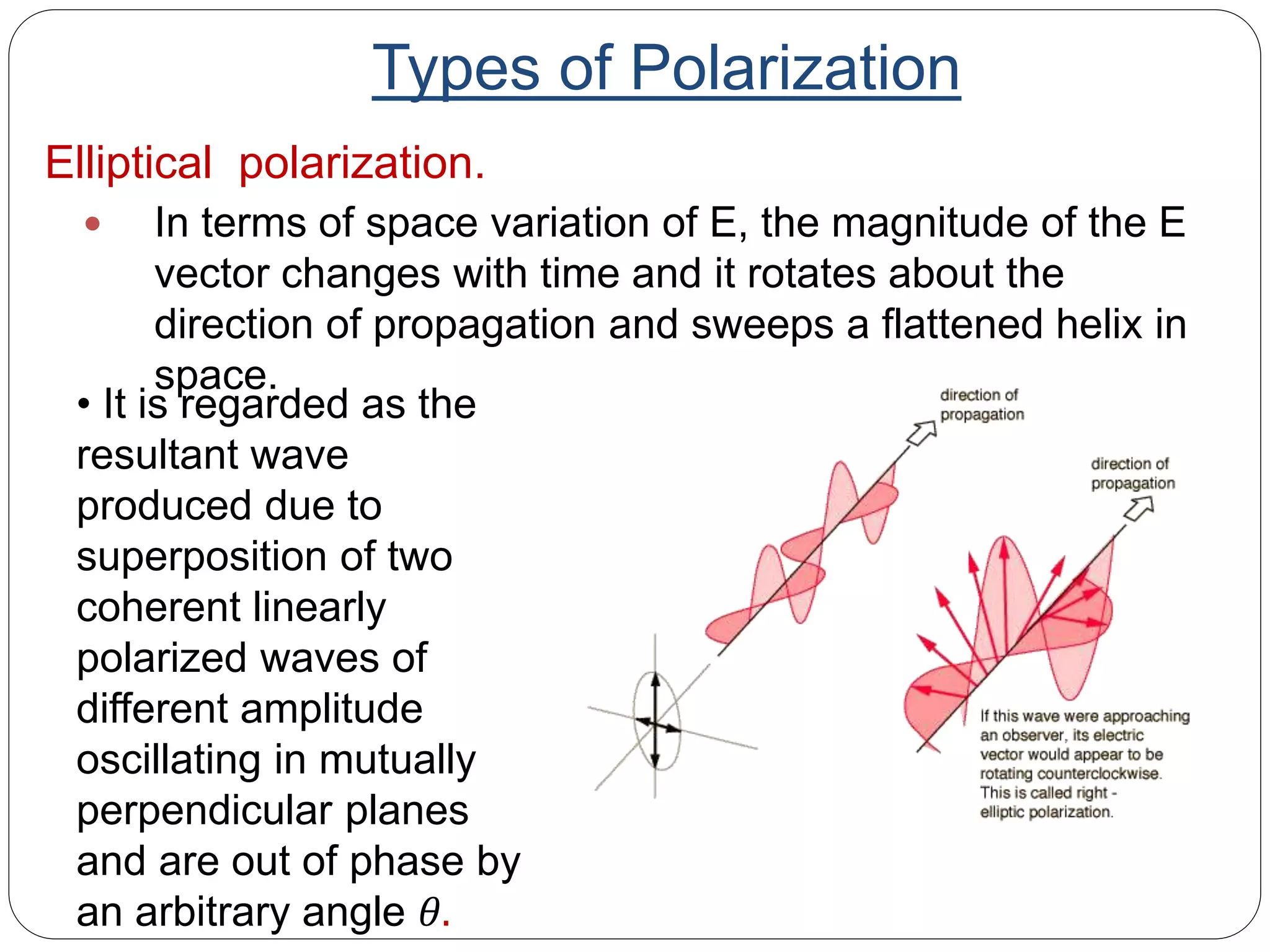
Different states of polarization: linear, circular, and elliptical; explanations of each type's characteristics and behaviors.
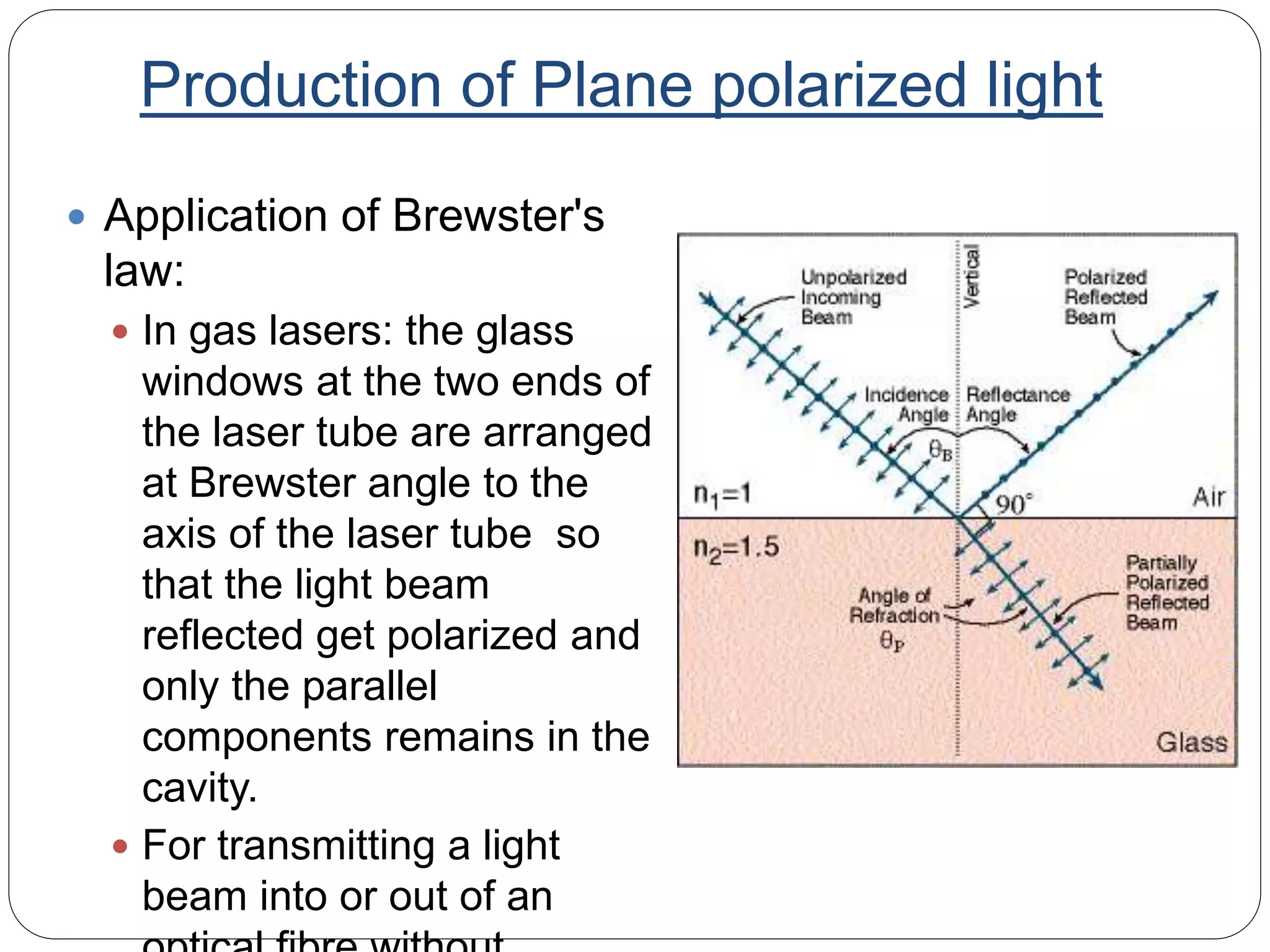
Methods of producing plane polarized light: reflection, refraction, and scattering; Brewster's angle and its applications.
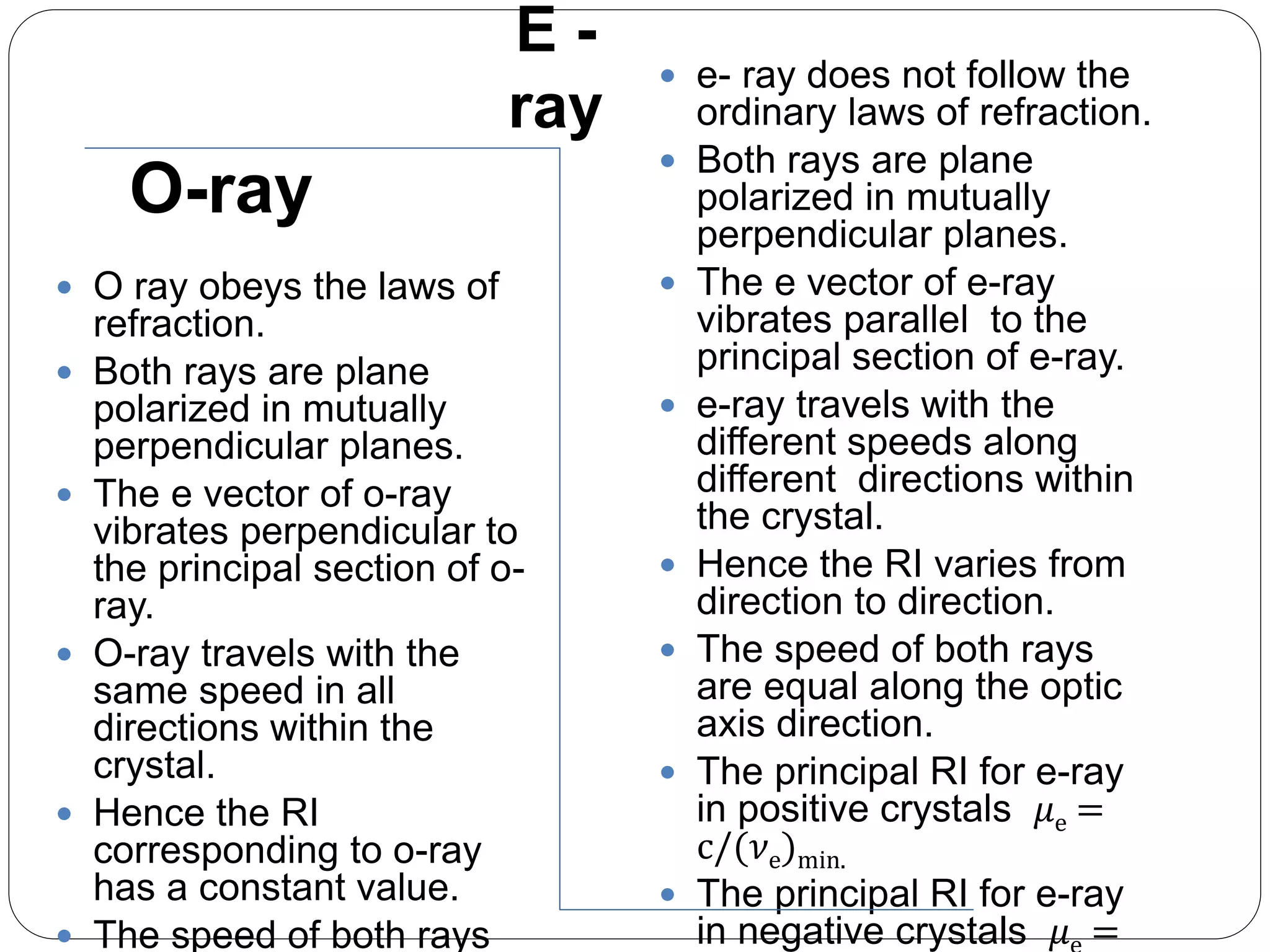
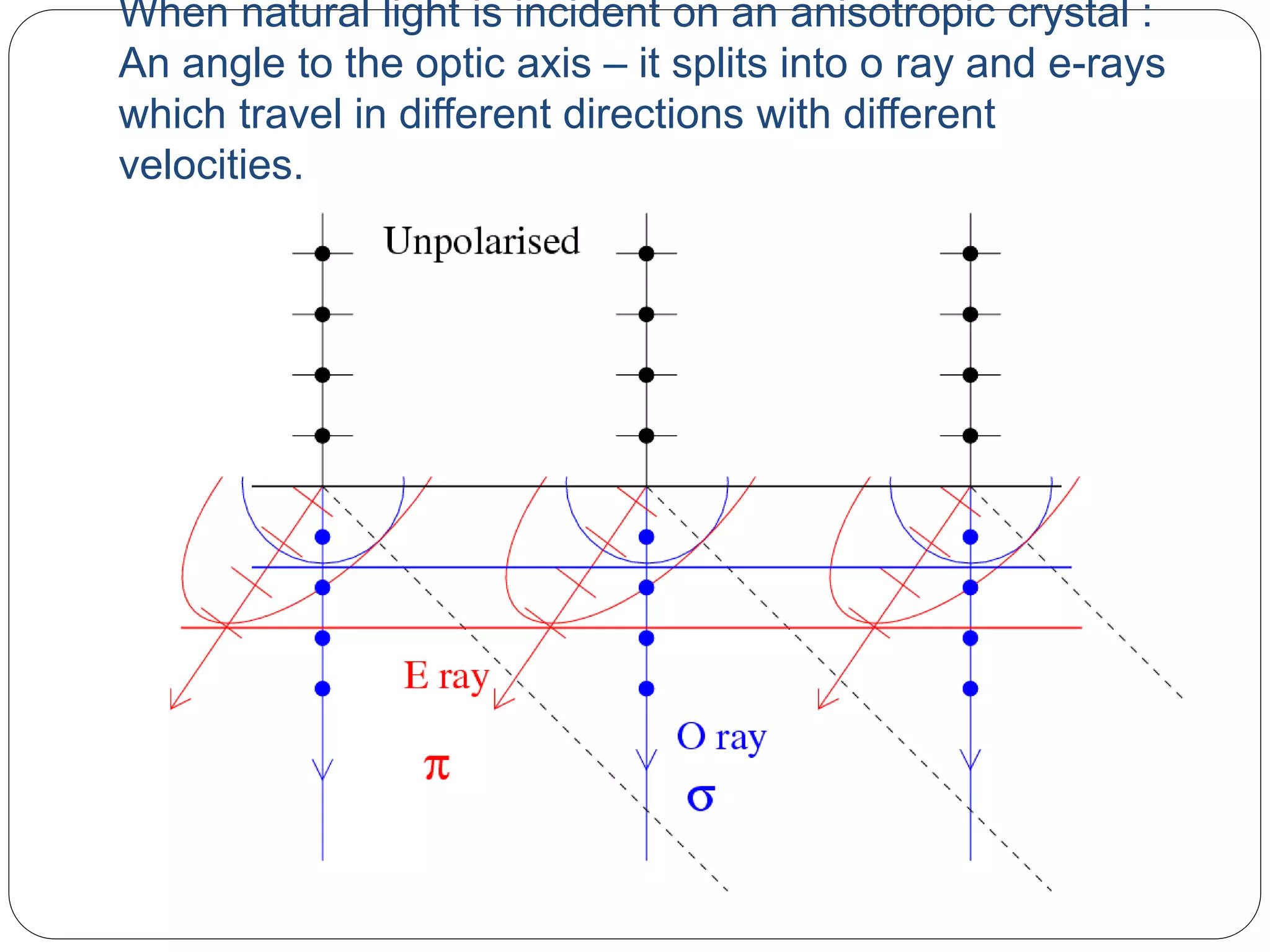
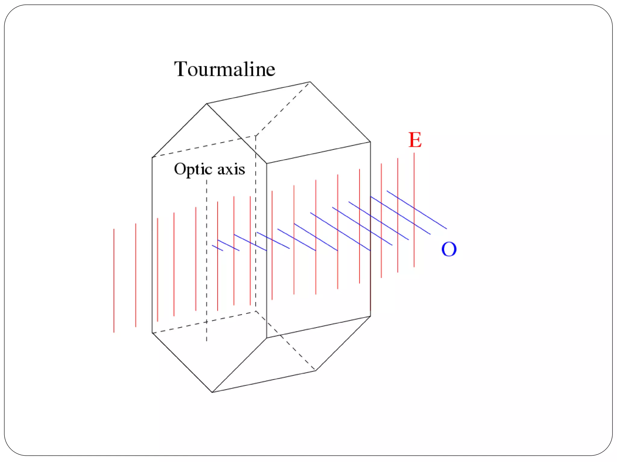
Huygen's theory describing how light splits into O-ray and E-ray in birefringent crystals; their velocity differences.
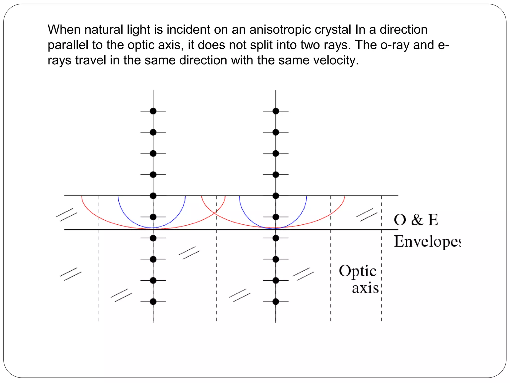
Melting behaviors of O-ray and E-ray in anisotropic crystals based on their direction in relation to the optic axis.
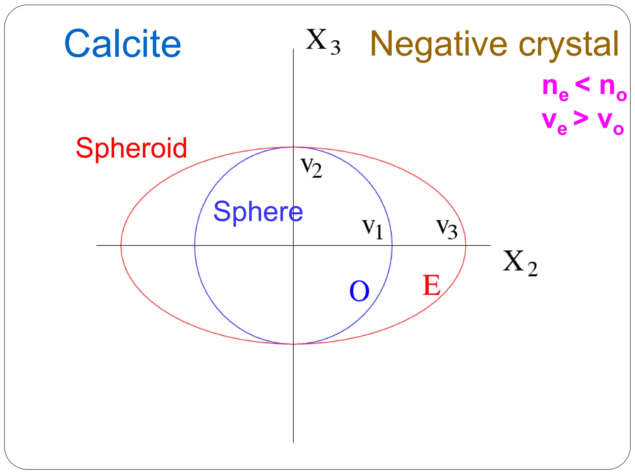
Comparison of positive and negative crystals; explaining differences in ray velocities and refractive indices.
Analysis of phase difference between O-ray and E-ray based on optical path; resulting polarization states.
Discussion of retarders, such as quarter-wave and half-wave plates; their use in altering the polarization state.