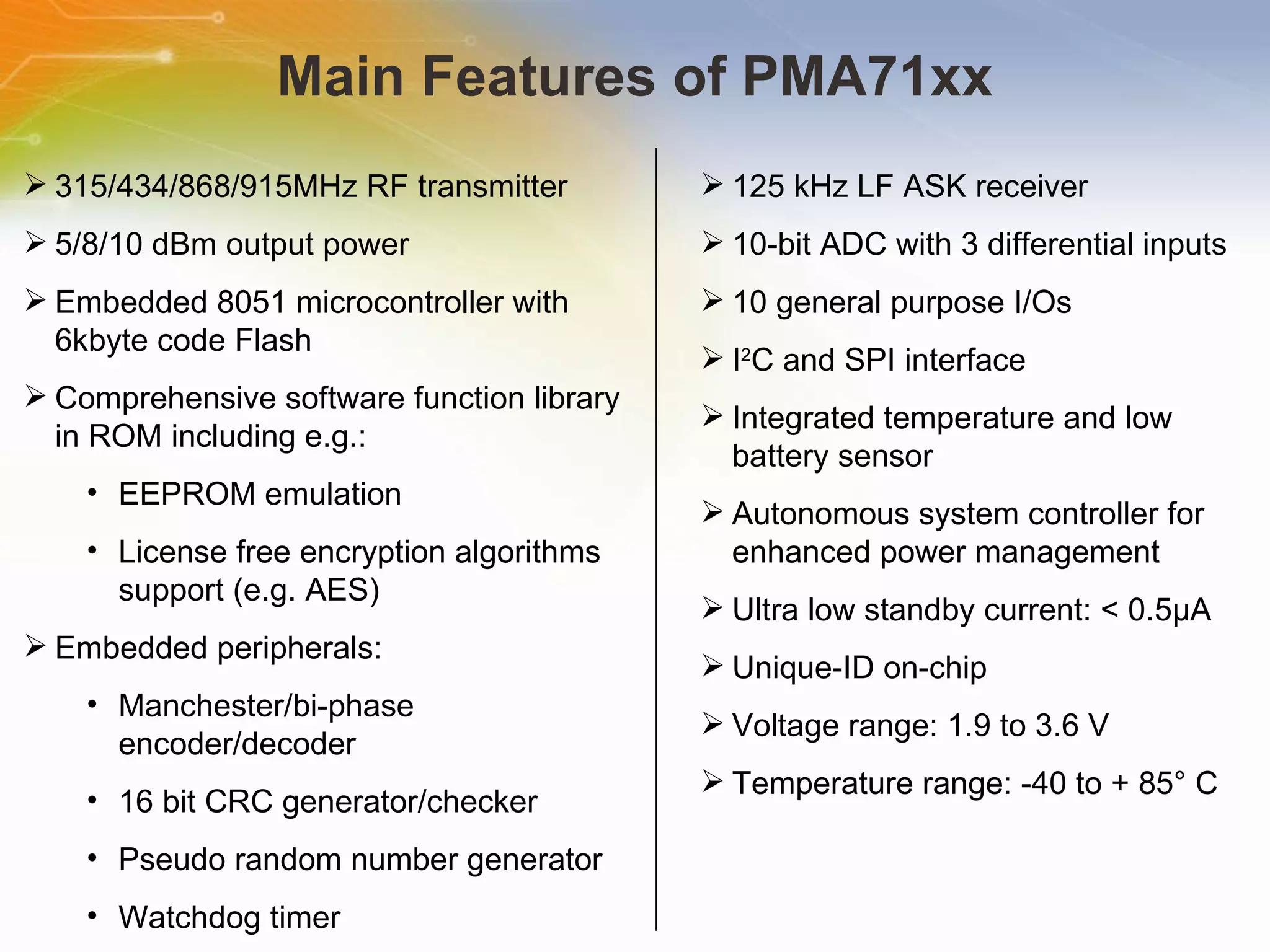
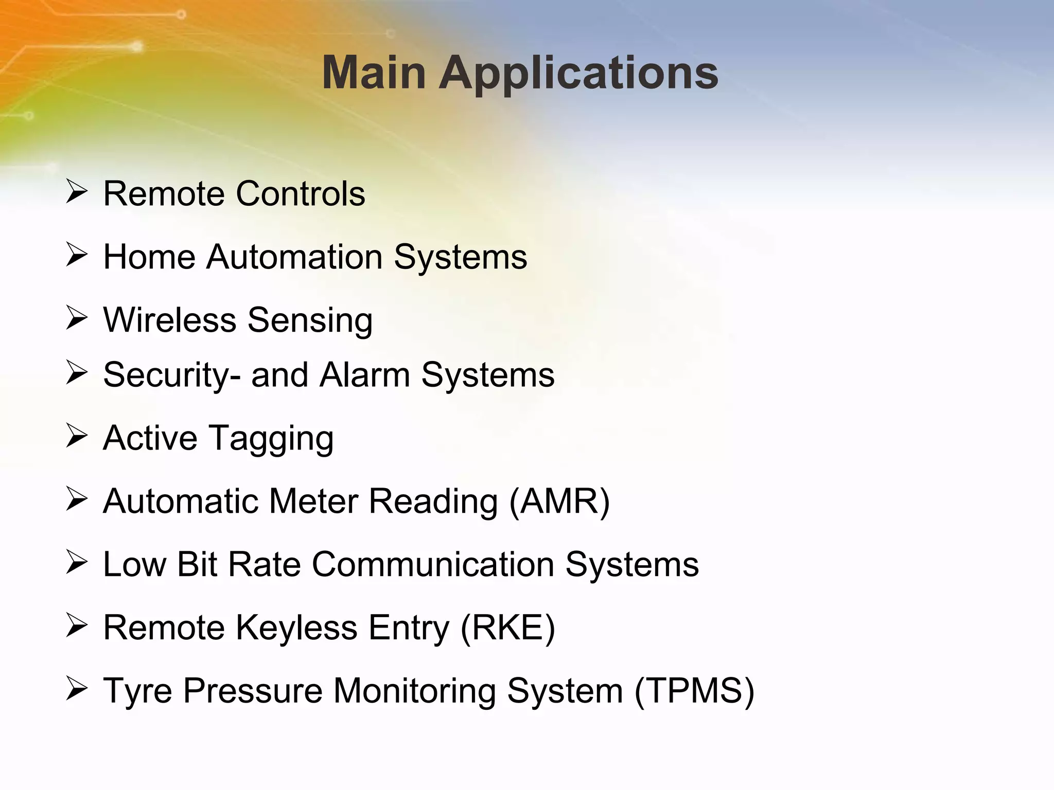
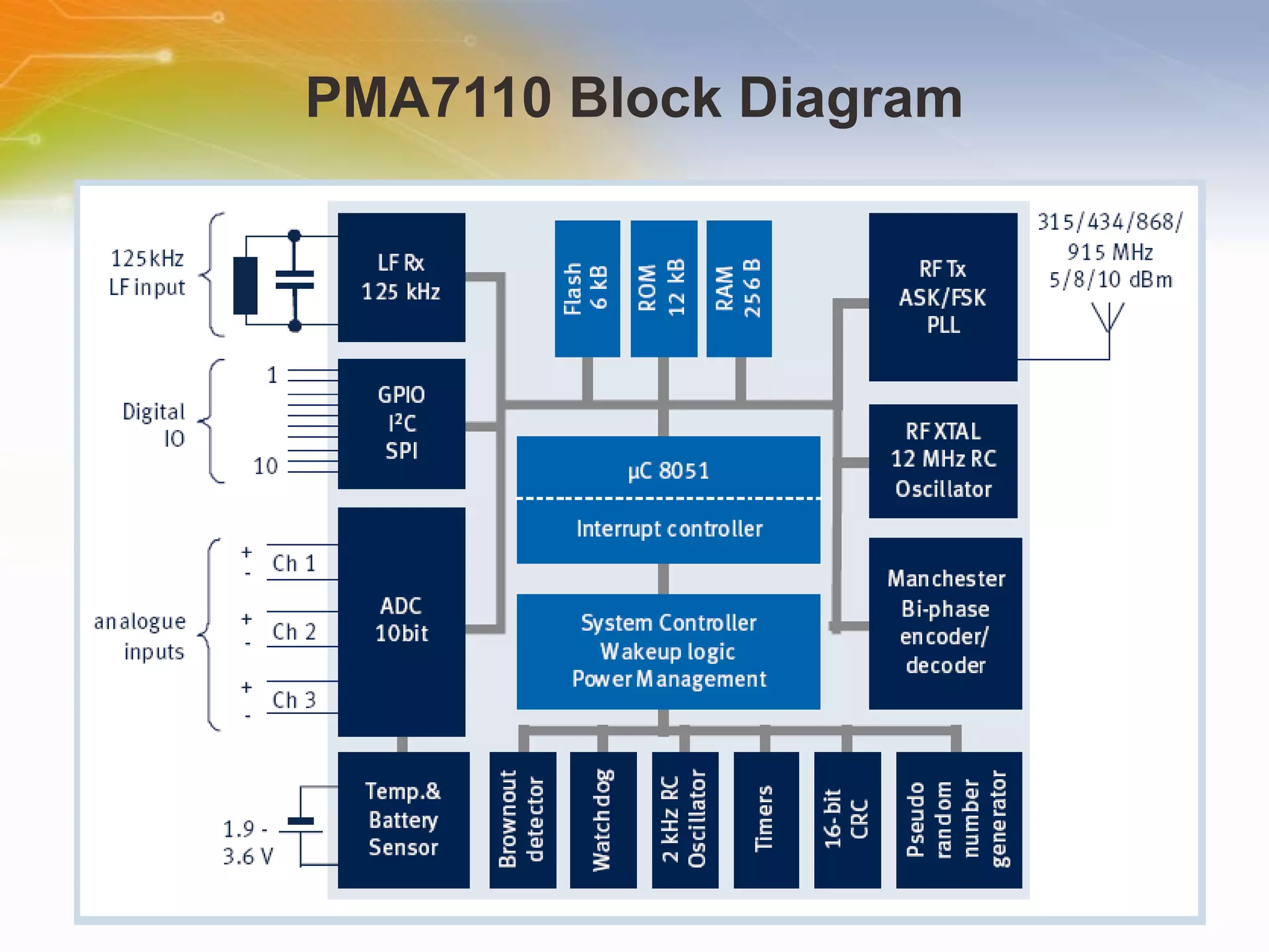
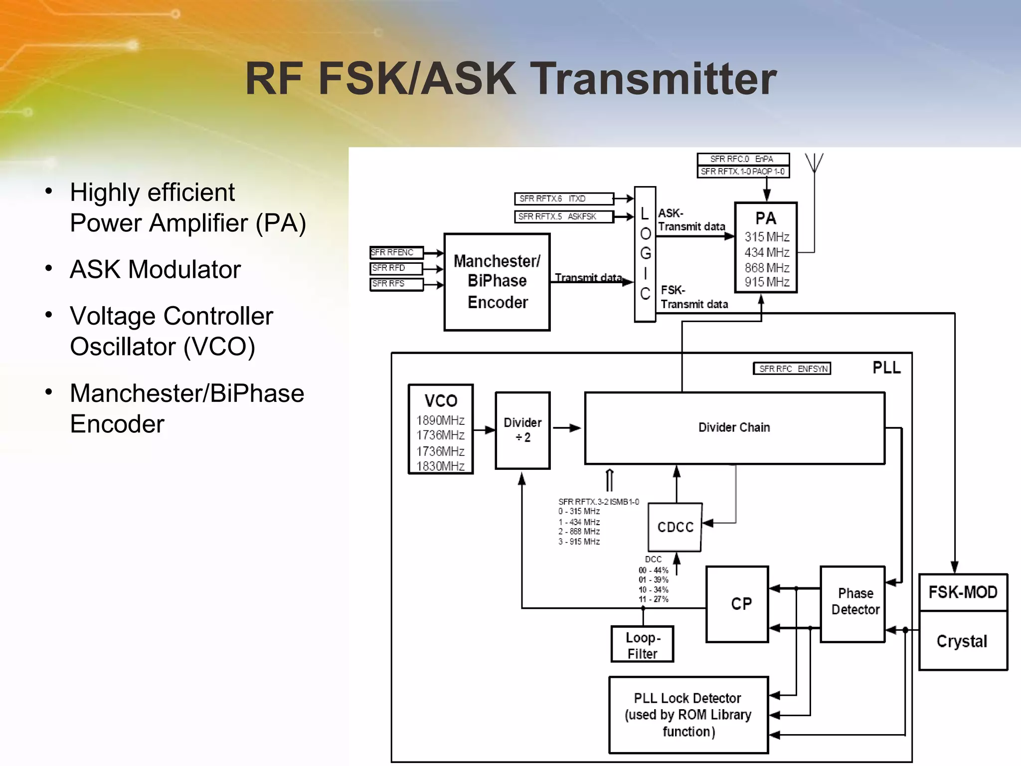
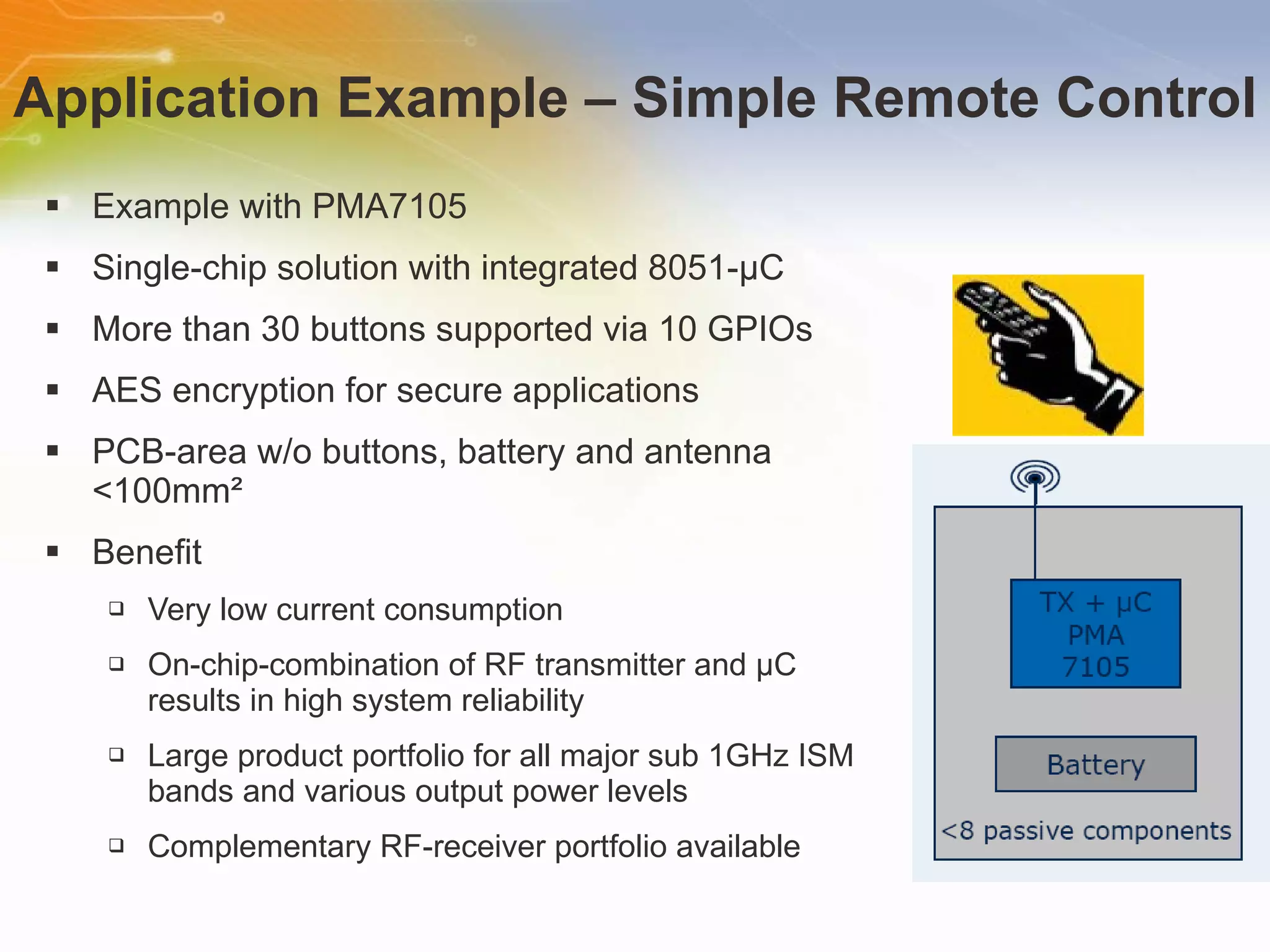
The document introduces the SmartLEWISTM MCU from Infineon, a single chip with an integrated 8051 microcontroller and ASK/FSK multi-band transmitter for sub-1GHz ISM frequency bands. It has flexibility in design, high level integration, and various power and sensor interfaces. Main applications include remote controls, home automation, security systems, and wireless sensor networks.
Arm Processor Based Speed Control Of BLDC MotorUday Wankar
The project is designed to control the speed of a DC motor using an ARM series processor. The speed of DC motor is directly proportional to the voltage applied across its terminals. Hence, if voltage across motor terminal is varied, then speed can also be varied. This project uses the above principle to control the speed of the motor by varying the duty cycle of the pulse applied to it (popularly known as PWM control). The project uses input button interfaced to the processor, which are used to control the speed of motor. PWM (Pulse Width Modulation) is generated at the output by the microcontroller as per the program. The program is written in Embedded C. The average voltage given or the average current flowing through the motor will change depending on the duty cycle (ON and OFF time of the pulses), so the speed of the motor will change. A motor driver IC is interfaced to the STM32 board for receiving PWM signals and delivering desired output for speed control of a small DC motor. Further the project can be enhanced by using power electronic devices such as IGBTs to achieve speed control higher capacity industrial motors.
Microcontrollers of Texas instruments
MSP430F5xx is the fifth series of the MSP430 family.
the neat block diagram along with their functioning was explained in the slide.
Microcontrollers of Texas instruments
MSP430F5xx is the fifth series of the MSP430 family.
the neat block diagram along with their functioning was explained in the slide.
Wireless energy meter monitoring with automated tariff calculationUdayalakshmi JK
Electricity billing has become a difficult task. The board has to make regular visit to the consumers house to make the reading. Also it can cause manual error. Now here we are monitoring the energy meter with modern techniques. The total energy consumed by the consumer and the consumption cost is known to the consumer and to the board by means of a hand held device.
Smart TV Buyer Insights Survey 2024 by 91mobiles.pdf91mobiles
91mobiles recently conducted a Smart TV Buyer Insights Survey in which we asked over 3,000 respondents about the TV they own, aspects they look at on a new TV, and their TV buying preferences.
Securing your Kubernetes cluster_ a step-by-step guide to success !KatiaHIMEUR1
Today, after several years of existence, an extremely active community and an ultra-dynamic ecosystem, Kubernetes has established itself as the de facto standard in container orchestration. Thanks to a wide range of managed services, it has never been so easy to set up a ready-to-use Kubernetes cluster.
However, this ease of use means that the subject of security in Kubernetes is often left for later, or even neglected. This exposes companies to significant risks.
In this talk, I'll show you step-by-step how to secure your Kubernetes cluster for greater peace of mind and reliability.
PHP Frameworks: I want to break free (IPC Berlin 2024)Ralf Eggert
In this presentation, we examine the challenges and limitations of relying too heavily on PHP frameworks in web development. We discuss the history of PHP and its frameworks to understand how this dependence has evolved. The focus will be on providing concrete tips and strategies to reduce reliance on these frameworks, based on real-world examples and practical considerations. The goal is to equip developers with the skills and knowledge to create more flexible and future-proof web applications. We'll explore the importance of maintaining autonomy in a rapidly changing tech landscape and how to make informed decisions in PHP development.
This talk is aimed at encouraging a more independent approach to using PHP frameworks, moving towards a more flexible and future-proof approach to PHP development.
Observability Concepts EVERY Developer Should Know -- DeveloperWeek Europe.pdfPaige Cruz
Monitoring and observability aren’t traditionally found in software curriculums and many of us cobble this knowledge together from whatever vendor or ecosystem we were first introduced to and whatever is a part of your current company’s observability stack.
While the dev and ops silo continues to crumble….many organizations still relegate monitoring & observability as the purview of ops, infra and SRE teams. This is a mistake - achieving a highly observable system requires collaboration up and down the stack.
I, a former op, would like to extend an invitation to all application developers to join the observability party will share these foundational concepts to build on:
UiPath Test Automation using UiPath Test Suite series, part 3DianaGray10
Welcome to UiPath Test Automation using UiPath Test Suite series part 3. In this session, we will cover desktop automation along with UI automation.
Topics covered:
UI automation Introduction,
UI automation Sample
Desktop automation flow
Pradeep Chinnala, Senior Consultant Automation Developer @WonderBotz and UiPath MVP
Deepak Rai, Automation Practice Lead, Boundaryless Group and UiPath MVP
Epistemic Interaction - tuning interfaces to provide information for AI supportAlan Dix
Paper presented at SYNERGY workshop at AVI 2024, Genoa, Italy. 3rd June 2024
https://alandix.com/academic/papers/synergy2024-epistemic/
As machine learning integrates deeper into human-computer interactions, the concept of epistemic interaction emerges, aiming to refine these interactions to enhance system adaptability. This approach encourages minor, intentional adjustments in user behaviour to enrich the data available for system learning. This paper introduces epistemic interaction within the context of human-system communication, illustrating how deliberate interaction design can improve system understanding and adaptation. Through concrete examples, we demonstrate the potential of epistemic interaction to significantly advance human-computer interaction by leveraging intuitive human communication strategies to inform system design and functionality, offering a novel pathway for enriching user-system engagements.
The Art of the Pitch: WordPress Relationships and SalesLaura Byrne
Clients don’t know what they don’t know. What web solutions are right for them? How does WordPress come into the picture? How do you make sure you understand scope and timeline? What do you do if sometime changes?
All these questions and more will be explored as we talk about matching clients’ needs with what your agency offers without pulling teeth or pulling your hair out. Practical tips, and strategies for successful relationship building that leads to closing the deal.
GraphRAG is All You need? LLM & Knowledge GraphGuy Korland
Guy Korland, CEO and Co-founder of FalkorDB, will review two articles on the integration of language models with knowledge graphs.
1. Unifying Large Language Models and Knowledge Graphs: A Roadmap.
https://arxiv.org/abs/2306.08302
2. Microsoft Research's GraphRAG paper and a review paper on various uses of knowledge graphs:
https://www.microsoft.com/en-us/research/blog/graphrag-unlocking-llm-discovery-on-narrative-private-data/
Welcome to the training module on Infineon PMA71xx- SmartLEWIS™ MCUs. This training module introduces SmartLEWIS MCU, a single chip with an ASK/FSK multi-band Transmitter for the sub 1GHz ISM frequency bands and an integrated 8051 microcontroller.
The SmartLEWIS™ MCU family comprises an ASK/FSK transmitter for the sub 1GHz ISM frequency bands with embedded 8051 microcontroller as base functionality. Additionally, exciting peripheral functions are integrated, building a fully flexible and pin-compatible product family. The internal multi-channel 10-bit ADC with its flexible high-gain settings as interface is used for a broad variety of analog sensors. The integrated LF-Receiver enables wireless wake-up in battery operated applications with ultra-long-lifetime or even contactless configuration of the device. The SmartLEWIS™ MCU includes an advanced power control system making this family ideal for battery operated applications where low current consumption is necessary.
The PMA71xx family is a low-power wireless FSK/ASK transmitter with an embedded microcontroller that offers a single-chip solution for various industrial, consumer applications in frequency bands 315/434/868/915 MHz. With its highly integrated mixed-signal peripherals, the PMA71xx family requires only a few external components. The operating voltage range is 1.9 - 3.6 V.
Here are the areas of application where this device can be implemented: it can go into Remote controls, Home automation, Wireless sensing, Security and Alarm system, Automatic meter reading, Remote keyless entry, Tyre pressure monitoring system.
The PMA71xx family contains contain 8051-based microcontroller, advanced power-control system to minimize power consumption, RF transmitter, LF receiver, and m ultifunctional interface for external sensors and embedded temperature and battery voltage sensors. The integrated microcontroller is instruction set compatible to the standard 8051 processor. It is equipped with various peripherals enabling an easy implementation of customer-specific applications. To store the microcontroller application program code, an on-chip FLASH memory is integrated. The low power consumption FSK/ASK transmitter for 315/434/868/915 MHz frequency bands contains a fully integrated VCO, a PLL synthesizer, an ASK/ FSK modulator and an efficient power amplifier. Fine tuning of the center frequency can be done by an onchip capacitor bank.
Here shows various members in PMA71XX family with different packaging and resources available.
The PMA71xx can be operated in three different operating modes, NORMAL mode, PROGRAMMING mode, and DEBUG mode. The Mode Select is entered after the System Reset expires. The levels on the I/O pins PP0 and PP1 are latched by the System controller and read by the operating system to determine the mode of operation of the device. This figure shows how the MSE and Lockbyte 2 are also checked to determine the operating mode. The MSE, PP0 and PP1 levels must not change after reset release during the whole tMODE period.
For low power consumption and safety reasons the PMA71xx supports different operating states - RUN state, IDLE state and POWER DOWN (PDWN) mode. Transitions between these states are either application software controlled or managed automatically by the system controller. The INIT state is a transient state after the System Reset, which is entered when the settings of PP0, PP1, MSE, TSE and the Lockbyte 2 lead to Normal Mode. It is also a transient state before the state change between IDLE, PDWN and RUN under Normal Mode. In this state, the relevant SFRs get reset and the ROM routines initializes the system to its default values. In RUN state the CPU executes programs stored in ROM or FLASH memory. Peripherals are on or off according to the application program. In IDLE state, the CPU clock is disabled but Peripherals continues normal operation. In POWER DOWN state the CPU and its peripherals are powered down. The system controller, its SFRs, the XData memory and optional the lower 128 byte internal RAM are kept powered. The LF receiver will be switched on periodically if the LF on/off timer is enabled.
The PMA71xx features multiple fault protections which prevent the application from unexpected behaviour and deadlocks. Fault protection is done by Watchdog Timer, Vmin Detector, Flash Memory Checksum, Flash Sector Protection Control, ADC Measurement overflow and underflow. For operation security a watchdog timer is available to avoid application deadlocks. Vmin Detector will detect if the supply voltage is below the minimum value required to guarantee chip correct operation. A CRC FLASH Memory Checksum is stored in the FLASH memory. After Lockbytes III is written, the CRC checksum can be recalculated and checked by the application program for verification of program code if needed. If a single bit error in the Flash memory occurs it is corrected by the Flash internal Error Correction Coder. The ROM Library functions which perform measurements will return the over/underflow status in a status byte with the measurement result.
The PMA71xx has two internal sensors, two high sensitive differential analog interfaces with 4 programmable gain factors (from 76+-20%, 60+-20%, 50+-20% and 38+-20% ) and one standard differential analog interface (gain factor 1) to acquire environmental data. The analog data is acquired and digitalized by the internal 10 bit ADC. Measurement routines for acquiring temperature and battery voltage data are available within the ROM library functions. The sensor interface connects to the external sensors and to the internal (on-chip) temperature and battery voltage sensors. All signal channels can be configured for differential or single-ended operation. The input multiplexer selects one channel for the input signal and one channel for the reference voltage to the ADC.
Here shows the Memory organization. The ROM area is in 12kB ranges from 007F to 02FFF. To protect the ROM code against readout a hardware mechanism is implemented, thus a read operation from the ROM in the protected address area returns zero. The FLASH is divided into five sectors as shown. Each sector can be erased and written individually. The RAM is available as data storage for the application program. ROM library functions may use some RAM locations for passing parameters and internal calculations.
The RF transmitter consists of a PLL Frequency synthesizer that is contained fully on chip, a lock detector and a power amplifier. The RF-Transmitter can be configured for the 315/434/868/915 MHz ISM-Band frequencies by setting SFR Bits and choosing the proper crystal. Manchester/BiPhase/NRZ coded data with a bit rate up to 32kbit/s (64kchips/s) can be transmitted using ASK or FSK modulation. The PLL synthesizer and the power amplifier can be enabled separately by using the SFR RFC control register. The power amplifier should be switched on with a delay of at least 100μs after enabling the frequency synthesizer. This delay is needed for PLL locking. The PLL consists of an on-chip VCO, an asynchronous divider chain with selectable overall division ratio, a phase detector with charge pump and an internal loop filter.
The LF receiver is used for data reception to the PMA71xx, as well as for waking up the PMA71xx from the POWER DOWN state. For applications requiring data reception, the LF receiver needs the 12MHz RC oscillator frequency as clock during data reception period. It can generate a wakeup directly by the carrier detector if the carrier amplitude is above a preset threshold, or it can decode the received data and not wake up the microcontroller until a predefined sync match pattern or wakeup pattern is detected in the data stream. Data recovery using a synchronizer and a decoder is available for Manchester and BiPhase coded data. A LF On/Off Timer is implemented to generate periodical On/Off switching of the LF receiver in POWER DOWN state. This can be done to reduce the current consumption.
The Serial Peripheral Interface, also known as SPI, is a very simple synchronous interface to transfer data on a serial bus, connecting an intelligent master controller with general-purpose slave circuits like slave controller, Rams, memories and so on. A simple 2-wire (half duplex mode) or 3-wire (full duplex mode) bus is used for communication. The SPI will operate in the master mode normally, thus the SPI has to drive the clock line (SPI_Clk). Therefore the SPI encloses a dedicated bit rate generator.
For communication between an external hardware and the PMA71xx, an I2C master/slave interface is implemented. The basic I2C-bus configuration is set for both master- and slave mode. This register is readable and writeable. The contained bits are partially set by software and reset by hardware or set and reset by software itself. The control register is only applicable in master mode; in slave mode all functional steps are executed automatically without external control. To enable the I2C interface, the SFR Bit I2CC.6[GCEn] has to be set. If a general call address is sent and bit I2CC.6 [GCEn] in control register is set the I2C bus behaves like a slave receiver
The PMA71xx comprises four independent 16 bit timers. Timer 0/1 operate as up counters, timer 2/3 operate as down-counters. Timer / counter 0 and 1 are fully compatible with Timer / counter 0 and 1 of the Standard 8051 and can be used in the same four operating modes as listed in the page. The external inputs PP1 and PP9 can be programmed to function as a gate for timer/counters 0 and 1 to facilitate pulse width measurements. Each timer consists of two 8 bit registers which may be combined to one timer configuration depending on the mode that is established. The functions of the timers are controlled by two special function registers TCON and TMOD. Timer 0 to Timer 3 comprise four fully programmable 16 bit timers, which can be used for time measurements as well as generating time delays.
Remote controls are widely used in daily life. Compared to low quality discrete SAW-based solutions, PLL based transmitters with integrated microcontroller have clear advantages in time-to-market, logistics cost and quality and reliability.
Remote keyless entry is widely used in modern cars. Compared to low quality discrete SAW-based solutions, PLL based transmitters with integrated microcontroller have clear advantages in time-to-market, logistics cost and quality and reliability.
Thank you for taking the time to view this presentation on PMA71xx- SmartLEWIS™ MCUs . If you would like to learn more or go on to purchase some of these devices, you may either click on the part list link, or simple call our sales hotline. For more technical information you may either visit the INFINEON site, or if you would prefer to speak to someone live, please call our hotline number, or even use our ‘live chat’ online facility.