Downloaded 17 times
![Clock[DIVIDE BY NETWORK]TIMER](https://image.slidesharecdn.com/inteliot-150414133802-conversion-gate01/85/Iot-Workshop-NITT-2015-13-320.jpg)
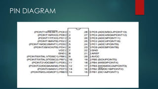
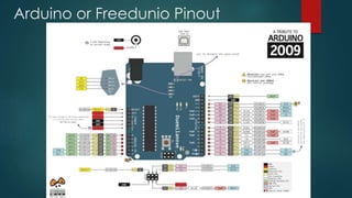
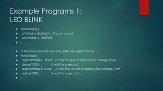
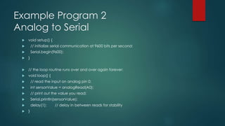


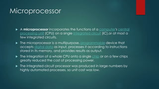
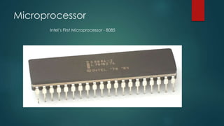
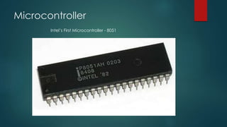
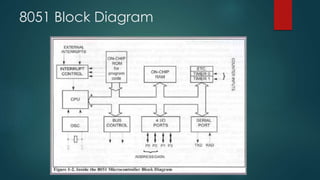
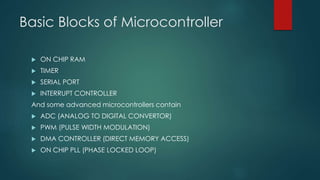
This document provides information about microprocessors, microcontrollers, and the Intel 8085 and 8051 chips. It discusses how a microprocessor incorporates a computer's central processing unit on a single integrated circuit, and how microcontrollers are designed for embedded applications. Key aspects of microcontrollers covered include on-chip RAM, timers, serial ports, interrupt controllers, analog-to-digital converters, and pulse width modulation controllers. An example block diagram and features are given for the Intel 8051 microcontroller. Example Arduino/Freeduino programs are also summarized.