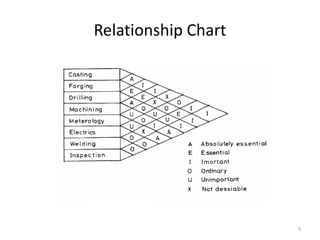
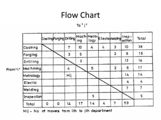
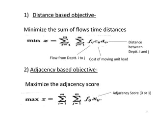
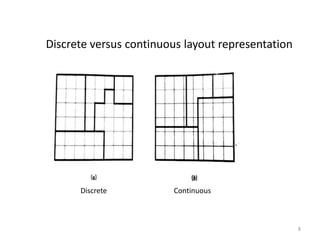
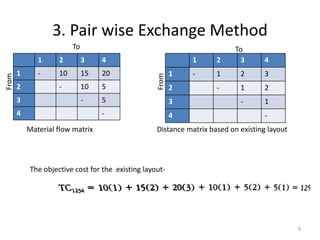
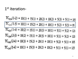
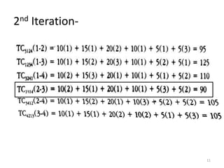
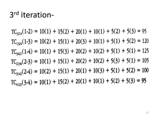
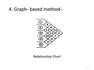
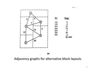
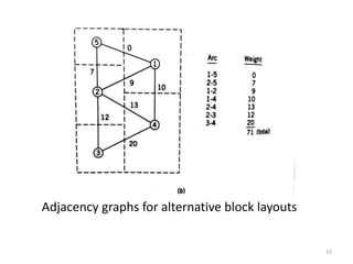
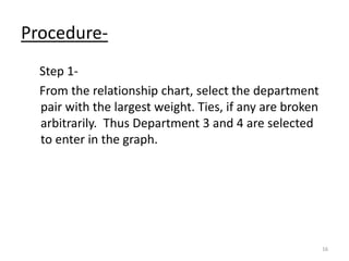
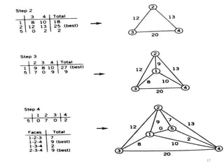
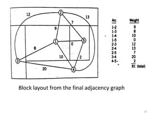
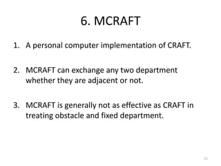
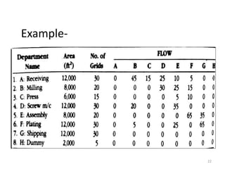
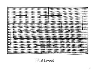
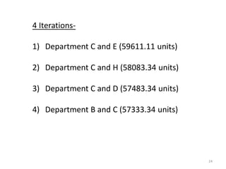
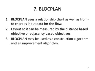
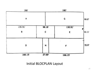
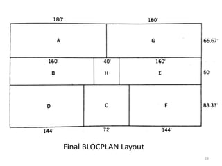
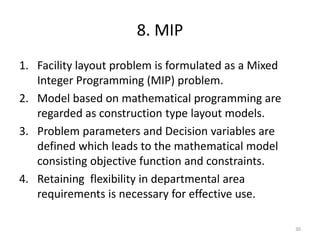
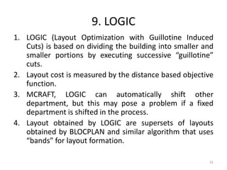
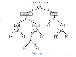
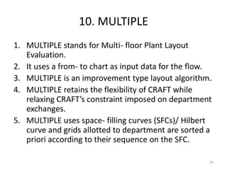
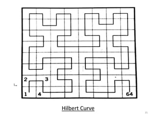
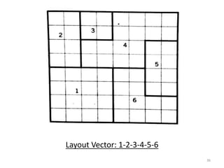
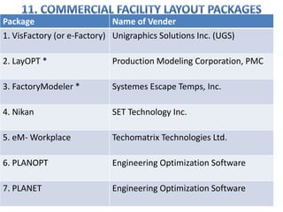
A
PRESENTATION
On
Plant Layout Algorithm and Software for Plant Layout
By
Shree Prasad Shukla(15EUCIM608)
M. Tech(IME) II SEM 1
OUTLINE
1. Algorithmic Approaches
2. Algorithm Classification
3. Pair wise Exchange Method
4. Graph- based Method
5. CRAFT
6. MCRAFT
7. BLOCPLAN
8. MIP
9. LOGIC
10. MULTIPLE
11. Commercial Facility Layout Packages
2
1. Algorithmic Approaches
1. Closeness ratings or material flow intensities can be
reduced to an algorithmic process.
2. Generating and numerically evaluating a large
number of layout alternatives in a very short time.
3. Performing “what if” analysis based on varying the
input data or the layout itself.
3
2. Algorithm Classification
1) Based on Relationship Chart or Flow Chart
2) Based on Distance- based objective and Adjacency-
based objective
3) Discrete and Continuous layout Representation
4) Primary function- layout improvement or layout
construction
4
Relationship Chart
5
Flow Chart
6
1) Distance based objective-
Minimize the sum of flows time distances
Flow from Deptt. i to j Cost of moving unit load
Distance
between
Deptt. i and j
2) Adjacency based objective-
Maximize the adjacency score
Adjacency Score (0 or 1)
7
8
Discrete versus continuous layout representation
Discrete Continuous
3. Pair wise Exchange Method
1 2 3 4
1 - 10 15 20
2 - 10 5
3 - 5
4 -
9
1 2 3 4
1 - 1 2 3
2 - 1 2
3 - 1
4 -
Material flow matrix Distance matrix based on existing layout
From
To
From
To
The objective cost for the existing layout-
1st iteration-
10
2nd Iteration-
11
3rd iteration-
12
Relationship Chart
13
4. Graph- based method-
14
Adjacency graphs for alternative block layouts
15
Adjacency graphs for alternative block layouts
Procedure-
Step 1-
From the relationship chart, select the department
pair with the largest weight. Ties, if any are broken
arbitrarily. Thus Department 3 and 4 are selected
to enter in the graph.
16
17
18
Block layout from the final adjacency graph
5. CRAFT
1. It stands for Computerized Relative Allocation of
Facilities Technique.
2. It uses from- to chart as input data.
3. CRAFT begins by determining the centroid of the
departments in the initial layout.
4. CRAFT next considers all- possible two-way(pair
wise) or three way exchanges and identifies the
best exchange.
5. The final layout obtained in such a manner is also
known as a two- opt(three- opt) layout.
19
20
6. Since CRAFT is not capable of automatically shifting
departments in such a manner, it considers exchanging
only those that are adjacent or equal in area.
7. A computerized layout algorithm narrows down the
solution space.
6. MCRAFT
1. A personal computer implementation of CRAFT.
2. MCRAFT can exchange any two department
whether they are adjacent or not.
3. MCRAFT is generally not as effective as CRAFT in
treating obstacle and fixed department.
21
22
Example-
23
Initial Layout
24
4 Iterations-
1) Department C and E (59611.11 units)
2) Department C and H (58083.34 units)
3) Department C and D (57483.34 units)
4) Department B and C (57333.34 units)
25
Final Layout
7. BLOCPLAN
1. BLOCPLAN uses a relationship chart as well as from-
to chart as input data for the flow.
2. Layout cost can be measured by the distance based
objective or adjacency based objectives.
3. BLOCPLAN may be used as a construction algorithm
and an improvement algorithm.
26
27
Initial BLOCPLAN Layout
28
Final BLOCPLAN Layout
29
The maximum flow between value = 90 units
Dividing the above maximum by 5, and then taking intervals accordingly
73 to 90 units (A) 55 to 72 units (E) 37 to 54 units (I)
19 to 36 units (O) 0 to 18 units (U)
8. MIP
1. Facility layout problem is formulated as a Mixed
Integer Programming (MIP) problem.
2. Model based on mathematical programming are
regarded as construction type layout models.
3. Problem parameters and Decision variables are
defined which leads to the mathematical model
consisting objective function and constraints.
4. Retaining flexibility in departmental area
requirements is necessary for effective use.
30
9. LOGIC
1. LOGIC (Layout Optimization with Guillotine Induced
Cuts) is based on dividing the building into smaller and
smaller portions by executing successive “guillotine”
cuts.
2. Layout cost is measured by the distance based objective
function.
3. MCRAFT, LOGIC can automatically shift other
department, but this may pose a problem if a fixed
department is shifted in the process.
4. Layout obtained by LOGIC are supersets of layouts
obtained by BLOCPLAN and similar algorithm that uses
“bands” for layout formation.
31
32Cut- tree
33
Final Layout
10. MULTIPLE
1. MULTIPLE stands for Multi- floor Plant Layout
Evaluation.
2. It uses a from- to chart as input data for the flow.
3. MULTIPLE is an improvement type layout algorithm.
4. MULTIPLE retains the flexibility of CRAFT while
relaxing CRAFT’s constraint imposed on department
exchanges.
5. MULTIPLE uses space- filling curves (SFCs)/ Hilbert
curve and grids allotted to department are sorted a
priori according to their sequence on the SFC.
34
35
Hilbert Curve
36
Layout Vector: 1-2-3-4-5-6
37
Package Name of Vender
1. VisFactory (or e-Factory) Unigraphics Solutions Inc. (UGS)
2. LayOPT * Production Modeling Corporation, PMC
3. FactoryModeler * Systemes Escape Temps, Inc.
4. Nikan SET Technology Inc.
5. eM- Workplace Techomatrix Technologies Ltd.
6. PLANOPT Engineering Optimization Software
7. PLANET Engineering Optimization Software
References
1. James A. Tompkins, John A. White, Yavuz A.
Bozer, J.M.A. Tanchoco, Facility Planning, 3rd
ed., John Wiley and Sons, Inc.,2003
2. http://www.ignou4u.in/ignou-ms-5-study-
materialbooks/
38
39

Plant Layout Algorithm

  • 1.
    A PRESENTATION On Plant Layout Algorithmand Software for Plant Layout By Shree Prasad Shukla(15EUCIM608) M. Tech(IME) II SEM 1
  • 2.
    OUTLINE 1. Algorithmic Approaches 2.Algorithm Classification 3. Pair wise Exchange Method 4. Graph- based Method 5. CRAFT 6. MCRAFT 7. BLOCPLAN 8. MIP 9. LOGIC 10. MULTIPLE 11. Commercial Facility Layout Packages 2
  • 3.
    1. Algorithmic Approaches 1.Closeness ratings or material flow intensities can be reduced to an algorithmic process. 2. Generating and numerically evaluating a large number of layout alternatives in a very short time. 3. Performing “what if” analysis based on varying the input data or the layout itself. 3
  • 4.
    2. Algorithm Classification 1)Based on Relationship Chart or Flow Chart 2) Based on Distance- based objective and Adjacency- based objective 3) Discrete and Continuous layout Representation 4) Primary function- layout improvement or layout construction 4
  • 5.
  • 6.
  • 7.
    1) Distance basedobjective- Minimize the sum of flows time distances Flow from Deptt. i to j Cost of moving unit load Distance between Deptt. i and j 2) Adjacency based objective- Maximize the adjacency score Adjacency Score (0 or 1) 7
  • 8.
    8 Discrete versus continuouslayout representation Discrete Continuous
  • 9.
    3. Pair wiseExchange Method 1 2 3 4 1 - 10 15 20 2 - 10 5 3 - 5 4 - 9 1 2 3 4 1 - 1 2 3 2 - 1 2 3 - 1 4 - Material flow matrix Distance matrix based on existing layout From To From To The objective cost for the existing layout-
  • 10.
  • 11.
  • 12.
  • 13.
  • 14.
    14 Adjacency graphs foralternative block layouts
  • 15.
    15 Adjacency graphs foralternative block layouts
  • 16.
    Procedure- Step 1- From therelationship chart, select the department pair with the largest weight. Ties, if any are broken arbitrarily. Thus Department 3 and 4 are selected to enter in the graph. 16
  • 17.
  • 18.
    18 Block layout fromthe final adjacency graph
  • 19.
    5. CRAFT 1. Itstands for Computerized Relative Allocation of Facilities Technique. 2. It uses from- to chart as input data. 3. CRAFT begins by determining the centroid of the departments in the initial layout. 4. CRAFT next considers all- possible two-way(pair wise) or three way exchanges and identifies the best exchange. 5. The final layout obtained in such a manner is also known as a two- opt(three- opt) layout. 19
  • 20.
    20 6. Since CRAFTis not capable of automatically shifting departments in such a manner, it considers exchanging only those that are adjacent or equal in area. 7. A computerized layout algorithm narrows down the solution space.
  • 21.
    6. MCRAFT 1. Apersonal computer implementation of CRAFT. 2. MCRAFT can exchange any two department whether they are adjacent or not. 3. MCRAFT is generally not as effective as CRAFT in treating obstacle and fixed department. 21
  • 22.
  • 23.
  • 24.
    24 4 Iterations- 1) DepartmentC and E (59611.11 units) 2) Department C and H (58083.34 units) 3) Department C and D (57483.34 units) 4) Department B and C (57333.34 units)
  • 25.
  • 26.
    7. BLOCPLAN 1. BLOCPLANuses a relationship chart as well as from- to chart as input data for the flow. 2. Layout cost can be measured by the distance based objective or adjacency based objectives. 3. BLOCPLAN may be used as a construction algorithm and an improvement algorithm. 26
  • 27.
  • 28.
  • 29.
    29 The maximum flowbetween value = 90 units Dividing the above maximum by 5, and then taking intervals accordingly 73 to 90 units (A) 55 to 72 units (E) 37 to 54 units (I) 19 to 36 units (O) 0 to 18 units (U)
  • 30.
    8. MIP 1. Facilitylayout problem is formulated as a Mixed Integer Programming (MIP) problem. 2. Model based on mathematical programming are regarded as construction type layout models. 3. Problem parameters and Decision variables are defined which leads to the mathematical model consisting objective function and constraints. 4. Retaining flexibility in departmental area requirements is necessary for effective use. 30
  • 31.
    9. LOGIC 1. LOGIC(Layout Optimization with Guillotine Induced Cuts) is based on dividing the building into smaller and smaller portions by executing successive “guillotine” cuts. 2. Layout cost is measured by the distance based objective function. 3. MCRAFT, LOGIC can automatically shift other department, but this may pose a problem if a fixed department is shifted in the process. 4. Layout obtained by LOGIC are supersets of layouts obtained by BLOCPLAN and similar algorithm that uses “bands” for layout formation. 31
  • 32.
  • 33.
  • 34.
    10. MULTIPLE 1. MULTIPLEstands for Multi- floor Plant Layout Evaluation. 2. It uses a from- to chart as input data for the flow. 3. MULTIPLE is an improvement type layout algorithm. 4. MULTIPLE retains the flexibility of CRAFT while relaxing CRAFT’s constraint imposed on department exchanges. 5. MULTIPLE uses space- filling curves (SFCs)/ Hilbert curve and grids allotted to department are sorted a priori according to their sequence on the SFC. 34
  • 35.
  • 36.
  • 37.
    37 Package Name ofVender 1. VisFactory (or e-Factory) Unigraphics Solutions Inc. (UGS) 2. LayOPT * Production Modeling Corporation, PMC 3. FactoryModeler * Systemes Escape Temps, Inc. 4. Nikan SET Technology Inc. 5. eM- Workplace Techomatrix Technologies Ltd. 6. PLANOPT Engineering Optimization Software 7. PLANET Engineering Optimization Software
  • 38.
    References 1. James A.Tompkins, John A. White, Yavuz A. Bozer, J.M.A. Tanchoco, Facility Planning, 3rd ed., John Wiley and Sons, Inc.,2003 2. http://www.ignou4u.in/ignou-ms-5-study- materialbooks/ 38
  • 39.