Downloaded 191 times
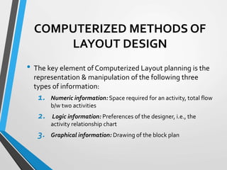

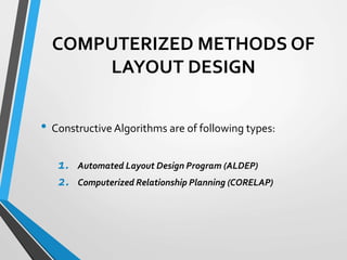
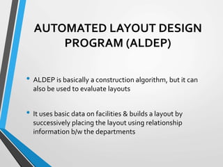


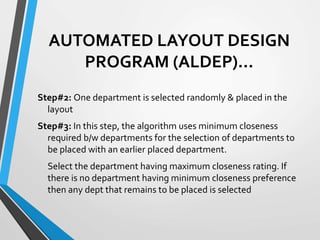


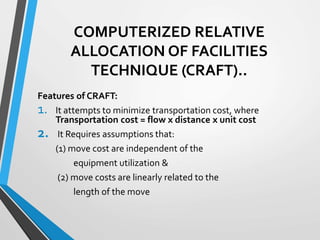
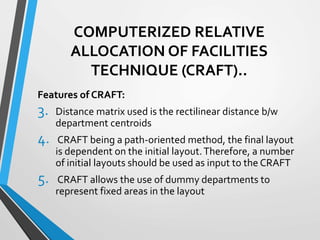


Computerized layout design methods use algorithms to represent space requirements, activity relationships, and graphical information to generate layouts. There are two main algorithm types: constructive algorithms which build layouts and improvement algorithms which optimize initial layouts. Examples of constructive algorithms are ALDEP and CORELAP, while CRAFT is an improvement algorithm that starts with an initial layout and iteratively exchanges departments to reduce transportation costs until no further improvements are possible. These computerized methods require inputs like area requirements, relationship charts, and flow data to systematically generate optimized layouts.


![Production & Operation Management Chapter28[1]](https://cdn.slidesharecdn.com/ss_thumbnails/chapter281-140613051706-phpapp01-thumbnail.jpg?width=640&height=640&fit=bounds)


