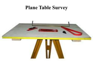
Plane Table Survey
Plane Table Surveying
• Plane Table Surveying is a graphical method of survey in which the
field observations and plotting are done simultaneously.
• It is simple and cheaper than theodolite survey. It is most suitable for
small scale maps.
• The plan is drawn by the surveyor in the field, while the area to be
surveyed is before his eyes.
• Therefore, there is no possibility of omitting the necessary
measurements.
Equipments and Accessories for Plane
Tabling
The following instruments are used in plane table surveying.
• Plane Table
• Tripod
• Alidade
• Tough Compass
• Plumbing fork and Plumb bob
• Spirit level
• Water proof cover
• Drawing paper
• Pins
• Drawing accessories
DIFFERENT TYPES OF PLANE TABLE
Johnson table
It is consists of a drawing board usually 45 x 60 cm or
60 x 75 c. the head consists of a ball and socket joint and
vertical spindle with two thumb screws and underside
Coast survey table
The leveling is done with the help of 3 foot screw. The table
can be turned about vertical axis and can be fixed in any
direction very accurately with the help of a clamp and
tangent screw.
Taverse table
It is consists of a small drawing board mounted on a light tripod
in such a way that the board can be rotated about the vertical
axis
Tripod
• The plane table is mounted on a tripod
• The tripod is generally of open frame type, combined rigidity with
lightness. The tripod may be made to fold for convenience of
transportation.
• Tripod is provided with three foot screws at its top for leveling of the
plane table.
Alidade
• The alidade is useful for establishing a line of sight.
• Two Types of alidade are used.
• Simple alidade
• Telescopic alidade
Simple Alidade
• It is used for ordinary work
• It is generally consists of a gun metal or wooden
rule with two vertical vanes at the ends.
• The eye-vane is provided with a narrow slit
while the object vane is open and carries a horse
hair. Both the slits, thus provide a definite line of
sight which can be made to pass through the
object to be sighted.
• To draw the rays, one of the edge of alidade is
beveled and this perfectly smooth working edge
is known as the fiducially edge.
• The fiducially edge is graduated to facilitate the
plotting of distances to a scale.
Telescopic Alidade
• The telescopic alidade is used when it is required to take inclined
sights.
• It essentially consists of a small telescope with a level tube and
graduated arc mounted on horizontal axis.
• It gives higher accuracy and more range of sights.
Trough Compass
Spirit Level
• A Spirit Level is used for ascertaining If the table is properly level.
• The Table is leveled by placing the level on the board in two positions
at right angles and getting the bubble central in both positions.
U-Fork With Plumb Bob
U-fork with plumb bob is used for centering the table over the point or station occupied by
the plane table when the plotted position of that point is already on the sheet.
Also, in the beginning of the work, it is used for transferring the ground point on the sheet.
Water Proof Cover
• An umbrella is used to protect the drawing paper from rain.
Drawing Paper
• Drawing paper is used for plotting the ground details.
• Principle Of Plane Table Survey
It is based on the principle that all the lines drawn on the drawing area parallel
to the corresponding lines on the ground, if the plane table is in properly
oriented positions.
Advantages of Plane Table Surveying
• The plan is drawn by the surveyor himself while the area to be surveyed is
before his eyes. Therefore, there is no possibility of omitting the necessary
measurements.
• The surveyor Can compare the plotted work with the actual features of the
area.
• It is simple and cheaper than the theodolite survey.
• It is most suitable for small scale maps.
• No great skill is required to produce a satisfactory map and work may be
entrusted to a subordinate.
• It is useful in magnetic areas where compass may not be used.
• The mistakes in writing field books are eliminated.
Disadvantages of Plane Table Surveying
• It is not intended for very accurate work.
• It is not suitable in monsoon.
Method Of Setting Up The Plane Table
• Three processes are involved in setting up the plane table over the
station.
• Leveling
• Centering
• Orientation
Leveling
Leveling and Centering
• The Table should be set up at convenient height for working on the
board, say about 1 m. The legs of Tripod should be spread well apart
and firmly into the ground.
Leveling and Centering
• For leveling the table ordinary spirit level may be used. The table is
leveled by placing the level on the board in two positions at right
angles and getting the bubble central in both directions.
• The table should be so placed over the station on the ground such that
the point plotted on the sheet corresponding to the station occupied
should be exactly over the station on the ground.
• The operation is known as centering the plane table. It is done by U-
fork and plumb bob.
Centering
Orientation
• The Process by which the positions occupied by the board at various
survey stations are kept parallel is known as the orientation. Thus,
when a plane table is properly oriented, the lines on the board are
parallel to the lines on ground which they represent.
• There are two methods of orientation:
• By magnetic needle
• By back sighting
By Magnetic Needle
• In this method, the magnetic north is drawn on paper at a particular station.
• At the next station, where the table is to be oriented, the compass is placed
against this line and the table is oriented by turning it until the needle floats
centrally.
• The board is then fixed in position by clamps. This method is inaccurate in
the since that the results are likely to be affected by the local attraction.
By Back Sighting
• A= First survey station
• B= Second survey station
• Suppose a line is drawn from station A on paper as ab, representing line
AB on ground
• The table is turned till the line of sight bisects the ranging rod at A. The
board is then clamped in this position.
• This method is better than the previous one and it gives perfect
orientation.
Methods Of Plane Tabling
• There are four distinct methods of plane tabling:
• Method of Radiation
• Method of Intersection
• Method of Traversing
• Method of Resection
Radiation Method
• In the radiation method of plane table surveying, the direction of the
objects or points to be located are obtained by drawing radial lines
along fiducially edge of alidade after getting the objects or points
bisected along the line of sight of the alidade. The horizontal
distances are then measured and scaled off on the corresponding
radial lines to mark their positions on the drawing.
Radiation Method
Radiation Method
• Suppose P is a station on the ground from where the object A, B, C and D
are visible.
• The plane table is set up over the station P. A drawing is fixed on the
table, which is then leveled and centered. A point p is selected on the
sheet to represent the station P.
• The north line is marked on the right-hand top corner of the sheet with
trough compass or circular box compass.
• With the alidade touching p, the ranging rod at A,B, C and D are bisected
and the rays are drawn.
• The distances PA, PB, PC and PD are measured and plotted to any
suitable scale to obtain the points a, b, c and d representing A,B,C,D on
paper.
Radiation Method
Method Of Intersection
• In intersection method of plane table surveying, the objects or points to be
located are obtained at the point of intersection of radial lines drawn from two
different stations.
• In this method, the plotting of plane table stations are to be carried out
accurately. Checking is important and thus done by taking third sight from
another station.
• The intersection method is suitable when distances of objects are large or
cannot be measured properly. Thus, this method is preferred in small scale
survey and for mountainous regions.
Method Of Intersection
• Suppose A and B are two station and P is the object on the far bank of
a river. Now it is required to fix the position of P on the sheet by the
intersection of rays, drawn from A and B.
• The table is set up at A. It is leveled and centered so that a point a on
the sheet is just over the station A. The north line is marked on the
right-hand top corner, the Table is then clamped.
• With the alidade touching a, the object P and the ranging rod at B are
bisected, and rays are drawn through the fiducial edge on alidade,
Method Of Intersection
• The distance AB is measured and plotted to any suitable scale to
obtain point b.
• The table is shifted and centered over B and leveled properly. Now
the alidade is placed along the line ba and orientation is done by back
sighting
• With the alidade touching b, the object P is bisected and a ray is
drawn, suppose this ray intersects the previous rays at point p. the
point p is the required plotted position of P
Method Of Intersection
Method Of Traversing
• This method of plane table surveying is used to plot a traverse in cases
stations have not been previously plotted by some other methods. In this
method, traverse stations are first selected. The stations are plotted by
method of radiation by taking back sight on the preceding station and a
fore sight to the following station. Here distances are generally measured
by tachometric method and surveying work has to be performed with
great care.
Method Of Traversing
•Suppose A,B,C,D are the traverse stations,
•The table is set up at the station A, a suitable point a is
selected on the sheet in such a way that the whole area
may be plotted in the sheet. The table is centered, leveled
and clamped. The north line is marked on the right-hand
top corner of the sheet.
•With the alidade touching point a the ranging rod at B is
bisected and a ray is drawn. The distance AB is measured
and plotted to any suitable scale.
Method Of Traversing
• The table is shifted touching point a the ranging rod at B is bisected
and a ray is drawn. The distance is measured and plotted to any
suitable scale.
• The table is shifted and centered over B. It is then leveled, oriented by
back sighting and clamped.
• With the alidade touching point b, the ranging rod at C is bisected and
ray is drawn. The distance BC is measured and plotted to the same
scale.
• The table is shifted and set up at C and the same procedure is
repeated.
• In this manner, all stations of the traverse are connected.
Method Of Traversing
• Check lines. To check the accuracy of the plane table traverse, a few
check lines are taken by sighting back to some preceding station.
•
• Error of closure . If the traverse to be plotted is a closed traverse, the
foresight from the terminating station should pass through the first
station. Otherwise the amount by which plotted position of the first
station on the foresight fails to close is designated as the error of closure.
• It is adjusted graphically, if the error is within permissible limits, before
any further plotting works are done.
Method Of Traversing
Resection is the process of determining the location of plane table station by
means of drawing rays from stations whose location of plane table station by
means of drawing rays from stations whose locations have already been
plotted.
There are four methods of resection.
• By Compass
• By back sighting
• By two point problem
• By three point problem
Resection
Method of Resection
• Suppose It is required to establish a station at position P. Let us select
two points A and B on the ground. The distance AB is measured and
plotted to any suitable scale. The line AB is known as the “base line”
• The table is set up at A. It is leveled, centered and oriented by bisecting
the ranging rod at B. The table is then clamped.
• With the alidade touching point a, the ranging rod at P is bisected and a
ray is drawn. Then a point P1 is marked on this way by estimating with
the eye.
Method of Resection
Method of Resection
• The table is shifted and centered in such a way that P1 is just over P. It
is then oriented by back-sighting the ranging rod at A.
• With the alidade touching point b, the ranging rod at B is bisected and
a ray is drawn. Suppose this ray intersects the previous ray at a point
P. This point represents the position of the station P on the sheet.
Then the actual position of the station is marked on the ground by U-
fork and plumb-bob
By Compass
• This method is used only for small scale or rough mapping.
• Let A and B be two visible stations which have been plotted on the
sheet as a and b. Let C be the instrument station to be located on the
plan.
• Set the table at C and orient it with compass. Clamp the table.
• Pivoting the alidade about a, draw a ray towards A, as Similarly,
pivoting the alidade about b, draw a ray towards B, as bb’, The
intersection of aa’ and bb’ will give point c on the paper.
By Compass
The Two Point Problem
• In this problem, two well-defined points whose positions have already
been plotted on the plan are selected. Then, by perfectly bisecting
these points, a new station is established at the required position.
The Two Point Problem
• Suppose P and Q are two well-defined points whose positions are
plotted on map as p and q. It is required to locate a new station at A by
perfectly bisecting P and Q
• An auxiliary station B is selected at a suitable position. The table is
set up at B, and leveled and oriented by eye estimation. It is then
clamped.
• With the alidade touching p and q, the points P and Q are bisected and
rays are drawn. Suppose these rays intersect at b
The Two Point Problem
• With the alidade centre on b, the ranging rod at A is bisected and rays
is drawn. Then, by eye estimation, a point a 1 is marked on this ray.
• The table is shifted and centre on A with a1 just over A. It is leveled
and oriented by back sighting. With the alidade touching p, the point P
is bisected and a ray is drawn. Suppose this ray intersects the line ba1
at point a1, as was assumed.
The Two Point Problem
• With the alidade centered on a1 the point Q is bisected and a ray is
drawn. Suppose this ray intersects the ray bq at a point q1. The triangle
pqq1 is known as the triangle of error, and is to be eliminated.
• The alidade is placed along the line pq1 and a ranging rod R is fixed at
some distance from the table. Then, the alidade is placed along the line
pq and the table is turned to bisect R. At this position the table is said to
be perfectly oriented.
• Finally, with the alidade centered on p and q, the points P and Q are
bisected and rays are drawn. Suppose these rays intersect at a point a.
This would represent the exact position of the required station A. Then
the station A is marked on the ground.
The Three Point Problem
• In this problem, three well defined points are selected, whose position
have already been plotted on the map. Then, by perfectly bisecting
these three well-defined points. A new station is established at the
required position.
• No auxiliary station is required in order to solve this problem. This
table is directly placed at the required position. The problem may be
solved by following methods
• (a) Bessel’s method
• (b) Mechanical Method
• (c) The trial and error method
The Three Point Problem
• The graphical method or Bessel’s method
• (i) suppose A,B, and C are three well-defined points which have been
plotted as a, b and c. Now it is required to locate a station at P.
• (ii) The table is placed at the required station P and leveled. The alidade
is placed along the line ca and the point A is bisected. The table is
clamped. With the alidade in centre on C, the point B is bisected and rays
is drawn
Bessel’s Method
The Three Point Problem
• Again the alidade is placed along the line ac and the point C is
bisected and the table is clamped. With the alidade touching a, the
point B is bisected and a ray is drawn. Suppose this ray intersects the
previous ray at a point d
• The alidade is placed along db and the point B is bisected. At this
position the table is said to be perfectly oriented. Now the rays Aa,
Bb and Cc are drawn. These three rays must meet at a point p which
is the required point on the map. This point is transferred to the
ground by U-fork and plumb bob.
The Three Point Problem
• The Mechanical Method
• Suppose A, B and C are the three well-defined points which have
been plotted on the map as a, b and c. It is required to locate a station
at P.
• The table is placed at P and leveled. A tracing paper is fixed on the
map and a point p is marked on it.
• With the alidade centered on P the points A, B and C are bisected and
rays are drawn. These rays may not pass through the points a, b and c
as the orientation is done approximately
The Mechanical Method
The Three Point Problem
• Now a tracing paper is unfastened and moved over the map in such a
way that the three rays simultaneously pass through the plotted
positions a, b and c. Then the points p is pricked with a pin to give an
impression p on the map. P is the required points on the map. The
tracing paper is then removed.
• Then the alidade is centered on p and the rays are drawn towards A, B
and C. These rays must pass through the points a, b and c
The Three Point Problem
• The method of Trial and error
• Suppose a, B and C are the three well-defined points which have been
plotted as a, b and c on the map. Now it is required to establish a station
at P.
• The table is set up at P and leveled. Orientation is done by eye estimation
• With the alidade, rays Aa, Bb and Cc are drawn. As the orientation is
approximately, the rays may not intersect at a point, but may form a
small triangle the triangle of error.
• To get the actual point, this triangle of error is to be eliminated. By
repeatedly turning the table clockwise or anticlockwise. The triangle is
eliminated in such a way that the rays Aa, Bb and Cc finally meet at a
point p. This is the required point on the map. This point is transferred to
the ground by U-fork and plumb bob.
The method of Trial and Error
Points to be kept in mind in plane tabling
• The following points should be kept in mind while doing plane table
survey.
• 1. Ground points shall be marked as A, B, C… etc. and plan. Points
(on Paper) shall be marked as a, b, c etc.
• 2. The rays from survey stations to the objects shall be drawn by
dashed line.
• 3. The alidade should be properly pivoted while sighting the objects
Points to be kept in mind in plane tabling
• 4. The first survey station and the scale of the map shall be so chosen
that the entire area can be plotted on the paper.
• 5. While establishing magnetic north on the paper using trough
compass, things causing local attraction shall be kept away of the
table.
• 6. The Plane table should be clamped after centering and leveling.
The table should be rotated at the time of orientation.
Error In Plane Tabling
• The various sources of error may be classified as :
• Instrumental errors
• Errors in manipulation and sighting
• Errors in plotting
Instrumental Errors
• The surface of drawing board is not plane
• The edge of alidade is not straight.
• The object vane and sight vane are not perpendicular to the alidade.
• The edge of alidade is not is not parallel to the line of sight.
• The fixing clamp is not proper.
Errors In Manipulation And Sighting
• Defective Leveling
• Defective Sighting
• Defective Orientation
• Defective Centering
• Movement of Board between sights
Errors in Plotting
• Defective scale of map
• Wrongly intersecting the rays drawn from two different stations.
Important Questions
• List Of Instruments used in plane tabling and give their uses.
• Give advantages and disadvantages of plane table survey.
• List of methods of plane table survey and explain any one.
• Explain the following methods of plane tabling.
• Method of intersection
• Method of traversing
• Explain the method of intersection for plane table survey.
• Explain the principle of plane table survey.
• Give limitations of plane table survey.
• What is orientation? Explain orientation by back sighting.
• Explain the procedure of plain table survey.
• Explain errors in plane table survey.

Plane_Table_Surveying.pptx

  • 1.
  • 2.
    Plane Table Surveying •Plane Table Surveying is a graphical method of survey in which the field observations and plotting are done simultaneously. • It is simple and cheaper than theodolite survey. It is most suitable for small scale maps. • The plan is drawn by the surveyor in the field, while the area to be surveyed is before his eyes. • Therefore, there is no possibility of omitting the necessary measurements.
  • 3.
    Equipments and Accessoriesfor Plane Tabling The following instruments are used in plane table surveying. • Plane Table • Tripod • Alidade • Tough Compass • Plumbing fork and Plumb bob • Spirit level • Water proof cover • Drawing paper • Pins • Drawing accessories
  • 4.
    DIFFERENT TYPES OFPLANE TABLE Johnson table It is consists of a drawing board usually 45 x 60 cm or 60 x 75 c. the head consists of a ball and socket joint and vertical spindle with two thumb screws and underside Coast survey table The leveling is done with the help of 3 foot screw. The table can be turned about vertical axis and can be fixed in any direction very accurately with the help of a clamp and tangent screw. Taverse table It is consists of a small drawing board mounted on a light tripod in such a way that the board can be rotated about the vertical axis
  • 5.
    Tripod • The planetable is mounted on a tripod • The tripod is generally of open frame type, combined rigidity with lightness. The tripod may be made to fold for convenience of transportation. • Tripod is provided with three foot screws at its top for leveling of the plane table.
  • 6.
    Alidade • The alidadeis useful for establishing a line of sight. • Two Types of alidade are used. • Simple alidade • Telescopic alidade
  • 7.
    Simple Alidade • Itis used for ordinary work • It is generally consists of a gun metal or wooden rule with two vertical vanes at the ends. • The eye-vane is provided with a narrow slit while the object vane is open and carries a horse hair. Both the slits, thus provide a definite line of sight which can be made to pass through the object to be sighted. • To draw the rays, one of the edge of alidade is beveled and this perfectly smooth working edge is known as the fiducially edge. • The fiducially edge is graduated to facilitate the plotting of distances to a scale.
  • 8.
    Telescopic Alidade • Thetelescopic alidade is used when it is required to take inclined sights. • It essentially consists of a small telescope with a level tube and graduated arc mounted on horizontal axis. • It gives higher accuracy and more range of sights.
  • 9.
  • 10.
    Spirit Level • ASpirit Level is used for ascertaining If the table is properly level. • The Table is leveled by placing the level on the board in two positions at right angles and getting the bubble central in both positions.
  • 11.
    U-Fork With PlumbBob U-fork with plumb bob is used for centering the table over the point or station occupied by the plane table when the plotted position of that point is already on the sheet. Also, in the beginning of the work, it is used for transferring the ground point on the sheet.
  • 12.
    Water Proof Cover •An umbrella is used to protect the drawing paper from rain.
  • 13.
    Drawing Paper • Drawingpaper is used for plotting the ground details.
  • 14.
    • Principle OfPlane Table Survey It is based on the principle that all the lines drawn on the drawing area parallel to the corresponding lines on the ground, if the plane table is in properly oriented positions.
  • 15.
    Advantages of PlaneTable Surveying • The plan is drawn by the surveyor himself while the area to be surveyed is before his eyes. Therefore, there is no possibility of omitting the necessary measurements. • The surveyor Can compare the plotted work with the actual features of the area. • It is simple and cheaper than the theodolite survey. • It is most suitable for small scale maps. • No great skill is required to produce a satisfactory map and work may be entrusted to a subordinate. • It is useful in magnetic areas where compass may not be used. • The mistakes in writing field books are eliminated. Disadvantages of Plane Table Surveying • It is not intended for very accurate work. • It is not suitable in monsoon.
  • 16.
    Method Of SettingUp The Plane Table • Three processes are involved in setting up the plane table over the station. • Leveling • Centering • Orientation
  • 17.
  • 18.
    Leveling and Centering •The Table should be set up at convenient height for working on the board, say about 1 m. The legs of Tripod should be spread well apart and firmly into the ground.
  • 19.
    Leveling and Centering •For leveling the table ordinary spirit level may be used. The table is leveled by placing the level on the board in two positions at right angles and getting the bubble central in both directions. • The table should be so placed over the station on the ground such that the point plotted on the sheet corresponding to the station occupied should be exactly over the station on the ground. • The operation is known as centering the plane table. It is done by U- fork and plumb bob.
  • 20.
  • 21.
    Orientation • The Processby which the positions occupied by the board at various survey stations are kept parallel is known as the orientation. Thus, when a plane table is properly oriented, the lines on the board are parallel to the lines on ground which they represent. • There are two methods of orientation: • By magnetic needle • By back sighting
  • 22.
    By Magnetic Needle •In this method, the magnetic north is drawn on paper at a particular station. • At the next station, where the table is to be oriented, the compass is placed against this line and the table is oriented by turning it until the needle floats centrally. • The board is then fixed in position by clamps. This method is inaccurate in the since that the results are likely to be affected by the local attraction.
  • 23.
    By Back Sighting •A= First survey station • B= Second survey station • Suppose a line is drawn from station A on paper as ab, representing line AB on ground • The table is turned till the line of sight bisects the ranging rod at A. The board is then clamped in this position. • This method is better than the previous one and it gives perfect orientation.
  • 24.
    Methods Of PlaneTabling • There are four distinct methods of plane tabling: • Method of Radiation • Method of Intersection • Method of Traversing • Method of Resection
  • 25.
    Radiation Method • Inthe radiation method of plane table surveying, the direction of the objects or points to be located are obtained by drawing radial lines along fiducially edge of alidade after getting the objects or points bisected along the line of sight of the alidade. The horizontal distances are then measured and scaled off on the corresponding radial lines to mark their positions on the drawing.
  • 26.
  • 27.
    Radiation Method • SupposeP is a station on the ground from where the object A, B, C and D are visible. • The plane table is set up over the station P. A drawing is fixed on the table, which is then leveled and centered. A point p is selected on the sheet to represent the station P. • The north line is marked on the right-hand top corner of the sheet with trough compass or circular box compass. • With the alidade touching p, the ranging rod at A,B, C and D are bisected and the rays are drawn. • The distances PA, PB, PC and PD are measured and plotted to any suitable scale to obtain the points a, b, c and d representing A,B,C,D on paper.
  • 28.
  • 29.
    Method Of Intersection •In intersection method of plane table surveying, the objects or points to be located are obtained at the point of intersection of radial lines drawn from two different stations. • In this method, the plotting of plane table stations are to be carried out accurately. Checking is important and thus done by taking third sight from another station. • The intersection method is suitable when distances of objects are large or cannot be measured properly. Thus, this method is preferred in small scale survey and for mountainous regions.
  • 30.
    Method Of Intersection •Suppose A and B are two station and P is the object on the far bank of a river. Now it is required to fix the position of P on the sheet by the intersection of rays, drawn from A and B. • The table is set up at A. It is leveled and centered so that a point a on the sheet is just over the station A. The north line is marked on the right-hand top corner, the Table is then clamped. • With the alidade touching a, the object P and the ranging rod at B are bisected, and rays are drawn through the fiducial edge on alidade,
  • 31.
  • 32.
    Method Of Intersection •The distance AB is measured and plotted to any suitable scale to obtain point b. • The table is shifted and centered over B and leveled properly. Now the alidade is placed along the line ba and orientation is done by back sighting • With the alidade touching b, the object P is bisected and a ray is drawn, suppose this ray intersects the previous rays at point p. the point p is the required plotted position of P
  • 33.
  • 34.
    Method Of Traversing •This method of plane table surveying is used to plot a traverse in cases stations have not been previously plotted by some other methods. In this method, traverse stations are first selected. The stations are plotted by method of radiation by taking back sight on the preceding station and a fore sight to the following station. Here distances are generally measured by tachometric method and surveying work has to be performed with great care.
  • 35.
    Method Of Traversing •SupposeA,B,C,D are the traverse stations, •The table is set up at the station A, a suitable point a is selected on the sheet in such a way that the whole area may be plotted in the sheet. The table is centered, leveled and clamped. The north line is marked on the right-hand top corner of the sheet. •With the alidade touching point a the ranging rod at B is bisected and a ray is drawn. The distance AB is measured and plotted to any suitable scale.
  • 36.
  • 37.
    Method Of Traversing •The table is shifted touching point a the ranging rod at B is bisected and a ray is drawn. The distance is measured and plotted to any suitable scale. • The table is shifted and centered over B. It is then leveled, oriented by back sighting and clamped. • With the alidade touching point b, the ranging rod at C is bisected and ray is drawn. The distance BC is measured and plotted to the same scale. • The table is shifted and set up at C and the same procedure is repeated. • In this manner, all stations of the traverse are connected.
  • 38.
    Method Of Traversing •Check lines. To check the accuracy of the plane table traverse, a few check lines are taken by sighting back to some preceding station. • • Error of closure . If the traverse to be plotted is a closed traverse, the foresight from the terminating station should pass through the first station. Otherwise the amount by which plotted position of the first station on the foresight fails to close is designated as the error of closure. • It is adjusted graphically, if the error is within permissible limits, before any further plotting works are done.
  • 39.
  • 40.
    Resection is theprocess of determining the location of plane table station by means of drawing rays from stations whose location of plane table station by means of drawing rays from stations whose locations have already been plotted. There are four methods of resection. • By Compass • By back sighting • By two point problem • By three point problem Resection
  • 41.
    Method of Resection •Suppose It is required to establish a station at position P. Let us select two points A and B on the ground. The distance AB is measured and plotted to any suitable scale. The line AB is known as the “base line” • The table is set up at A. It is leveled, centered and oriented by bisecting the ranging rod at B. The table is then clamped. • With the alidade touching point a, the ranging rod at P is bisected and a ray is drawn. Then a point P1 is marked on this way by estimating with the eye.
  • 42.
  • 43.
    Method of Resection •The table is shifted and centered in such a way that P1 is just over P. It is then oriented by back-sighting the ranging rod at A. • With the alidade touching point b, the ranging rod at B is bisected and a ray is drawn. Suppose this ray intersects the previous ray at a point P. This point represents the position of the station P on the sheet. Then the actual position of the station is marked on the ground by U- fork and plumb-bob
  • 44.
    By Compass • Thismethod is used only for small scale or rough mapping. • Let A and B be two visible stations which have been plotted on the sheet as a and b. Let C be the instrument station to be located on the plan. • Set the table at C and orient it with compass. Clamp the table. • Pivoting the alidade about a, draw a ray towards A, as Similarly, pivoting the alidade about b, draw a ray towards B, as bb’, The intersection of aa’ and bb’ will give point c on the paper.
  • 45.
  • 46.
    The Two PointProblem • In this problem, two well-defined points whose positions have already been plotted on the plan are selected. Then, by perfectly bisecting these points, a new station is established at the required position.
  • 47.
    The Two PointProblem • Suppose P and Q are two well-defined points whose positions are plotted on map as p and q. It is required to locate a new station at A by perfectly bisecting P and Q • An auxiliary station B is selected at a suitable position. The table is set up at B, and leveled and oriented by eye estimation. It is then clamped. • With the alidade touching p and q, the points P and Q are bisected and rays are drawn. Suppose these rays intersect at b
  • 48.
  • 49.
    The Two PointProblem • With the alidade centre on b, the ranging rod at A is bisected and rays is drawn. Then, by eye estimation, a point a 1 is marked on this ray. • The table is shifted and centre on A with a1 just over A. It is leveled and oriented by back sighting. With the alidade touching p, the point P is bisected and a ray is drawn. Suppose this ray intersects the line ba1 at point a1, as was assumed.
  • 50.
    The Two PointProblem • With the alidade centered on a1 the point Q is bisected and a ray is drawn. Suppose this ray intersects the ray bq at a point q1. The triangle pqq1 is known as the triangle of error, and is to be eliminated. • The alidade is placed along the line pq1 and a ranging rod R is fixed at some distance from the table. Then, the alidade is placed along the line pq and the table is turned to bisect R. At this position the table is said to be perfectly oriented. • Finally, with the alidade centered on p and q, the points P and Q are bisected and rays are drawn. Suppose these rays intersect at a point a. This would represent the exact position of the required station A. Then the station A is marked on the ground.
  • 51.
    The Three PointProblem • In this problem, three well defined points are selected, whose position have already been plotted on the map. Then, by perfectly bisecting these three well-defined points. A new station is established at the required position. • No auxiliary station is required in order to solve this problem. This table is directly placed at the required position. The problem may be solved by following methods • (a) Bessel’s method • (b) Mechanical Method • (c) The trial and error method
  • 52.
    The Three PointProblem • The graphical method or Bessel’s method • (i) suppose A,B, and C are three well-defined points which have been plotted as a, b and c. Now it is required to locate a station at P. • (ii) The table is placed at the required station P and leveled. The alidade is placed along the line ca and the point A is bisected. The table is clamped. With the alidade in centre on C, the point B is bisected and rays is drawn
  • 53.
  • 54.
    The Three PointProblem • Again the alidade is placed along the line ac and the point C is bisected and the table is clamped. With the alidade touching a, the point B is bisected and a ray is drawn. Suppose this ray intersects the previous ray at a point d • The alidade is placed along db and the point B is bisected. At this position the table is said to be perfectly oriented. Now the rays Aa, Bb and Cc are drawn. These three rays must meet at a point p which is the required point on the map. This point is transferred to the ground by U-fork and plumb bob.
  • 55.
    The Three PointProblem • The Mechanical Method • Suppose A, B and C are the three well-defined points which have been plotted on the map as a, b and c. It is required to locate a station at P. • The table is placed at P and leveled. A tracing paper is fixed on the map and a point p is marked on it. • With the alidade centered on P the points A, B and C are bisected and rays are drawn. These rays may not pass through the points a, b and c as the orientation is done approximately
  • 56.
  • 57.
    The Three PointProblem • Now a tracing paper is unfastened and moved over the map in such a way that the three rays simultaneously pass through the plotted positions a, b and c. Then the points p is pricked with a pin to give an impression p on the map. P is the required points on the map. The tracing paper is then removed. • Then the alidade is centered on p and the rays are drawn towards A, B and C. These rays must pass through the points a, b and c
  • 58.
    The Three PointProblem • The method of Trial and error • Suppose a, B and C are the three well-defined points which have been plotted as a, b and c on the map. Now it is required to establish a station at P. • The table is set up at P and leveled. Orientation is done by eye estimation • With the alidade, rays Aa, Bb and Cc are drawn. As the orientation is approximately, the rays may not intersect at a point, but may form a small triangle the triangle of error. • To get the actual point, this triangle of error is to be eliminated. By repeatedly turning the table clockwise or anticlockwise. The triangle is eliminated in such a way that the rays Aa, Bb and Cc finally meet at a point p. This is the required point on the map. This point is transferred to the ground by U-fork and plumb bob.
  • 59.
    The method ofTrial and Error
  • 60.
    Points to bekept in mind in plane tabling • The following points should be kept in mind while doing plane table survey. • 1. Ground points shall be marked as A, B, C… etc. and plan. Points (on Paper) shall be marked as a, b, c etc. • 2. The rays from survey stations to the objects shall be drawn by dashed line. • 3. The alidade should be properly pivoted while sighting the objects
  • 61.
    Points to bekept in mind in plane tabling
  • 62.
    Points to bekept in mind in plane tabling • 4. The first survey station and the scale of the map shall be so chosen that the entire area can be plotted on the paper. • 5. While establishing magnetic north on the paper using trough compass, things causing local attraction shall be kept away of the table. • 6. The Plane table should be clamped after centering and leveling. The table should be rotated at the time of orientation.
  • 63.
    Error In PlaneTabling • The various sources of error may be classified as : • Instrumental errors • Errors in manipulation and sighting • Errors in plotting
  • 64.
    Instrumental Errors • Thesurface of drawing board is not plane • The edge of alidade is not straight. • The object vane and sight vane are not perpendicular to the alidade. • The edge of alidade is not is not parallel to the line of sight. • The fixing clamp is not proper.
  • 65.
    Errors In ManipulationAnd Sighting • Defective Leveling • Defective Sighting • Defective Orientation • Defective Centering • Movement of Board between sights
  • 66.
    Errors in Plotting •Defective scale of map • Wrongly intersecting the rays drawn from two different stations.
  • 67.
    Important Questions • ListOf Instruments used in plane tabling and give their uses. • Give advantages and disadvantages of plane table survey. • List of methods of plane table survey and explain any one. • Explain the following methods of plane tabling. • Method of intersection • Method of traversing • Explain the method of intersection for plane table survey. • Explain the principle of plane table survey. • Give limitations of plane table survey. • What is orientation? Explain orientation by back sighting. • Explain the procedure of plain table survey. • Explain errors in plane table survey.