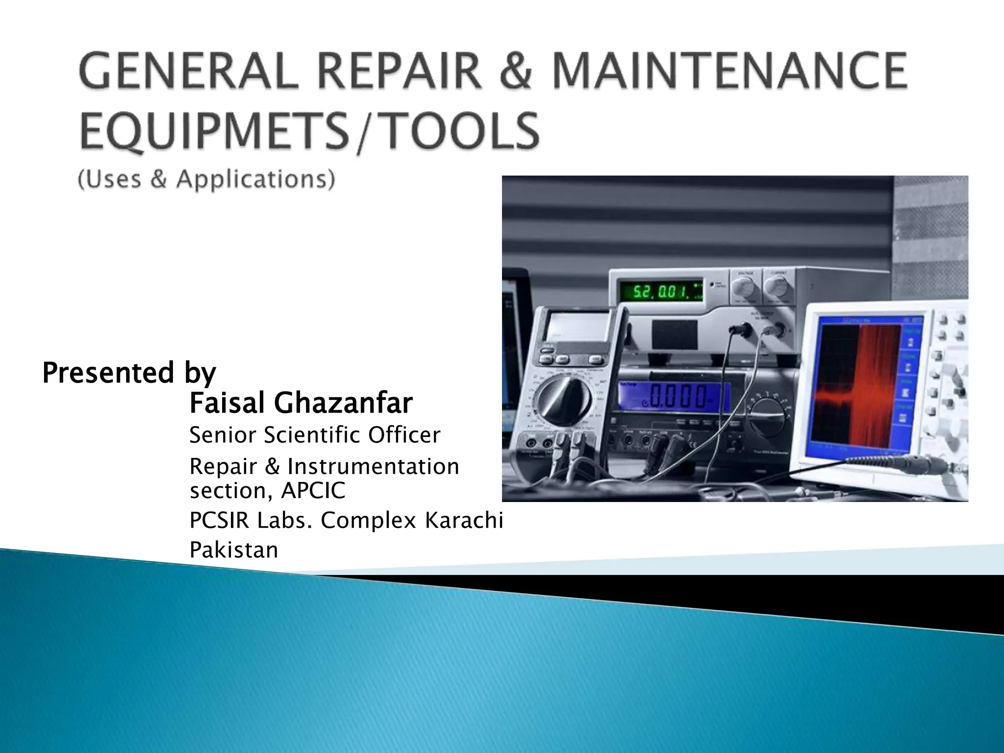
This document provides an overview of various tools and techniques used in electronics repair, including:
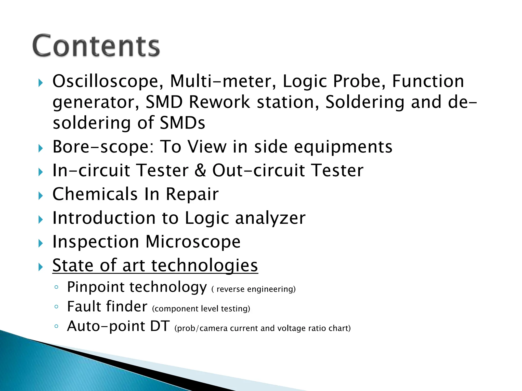
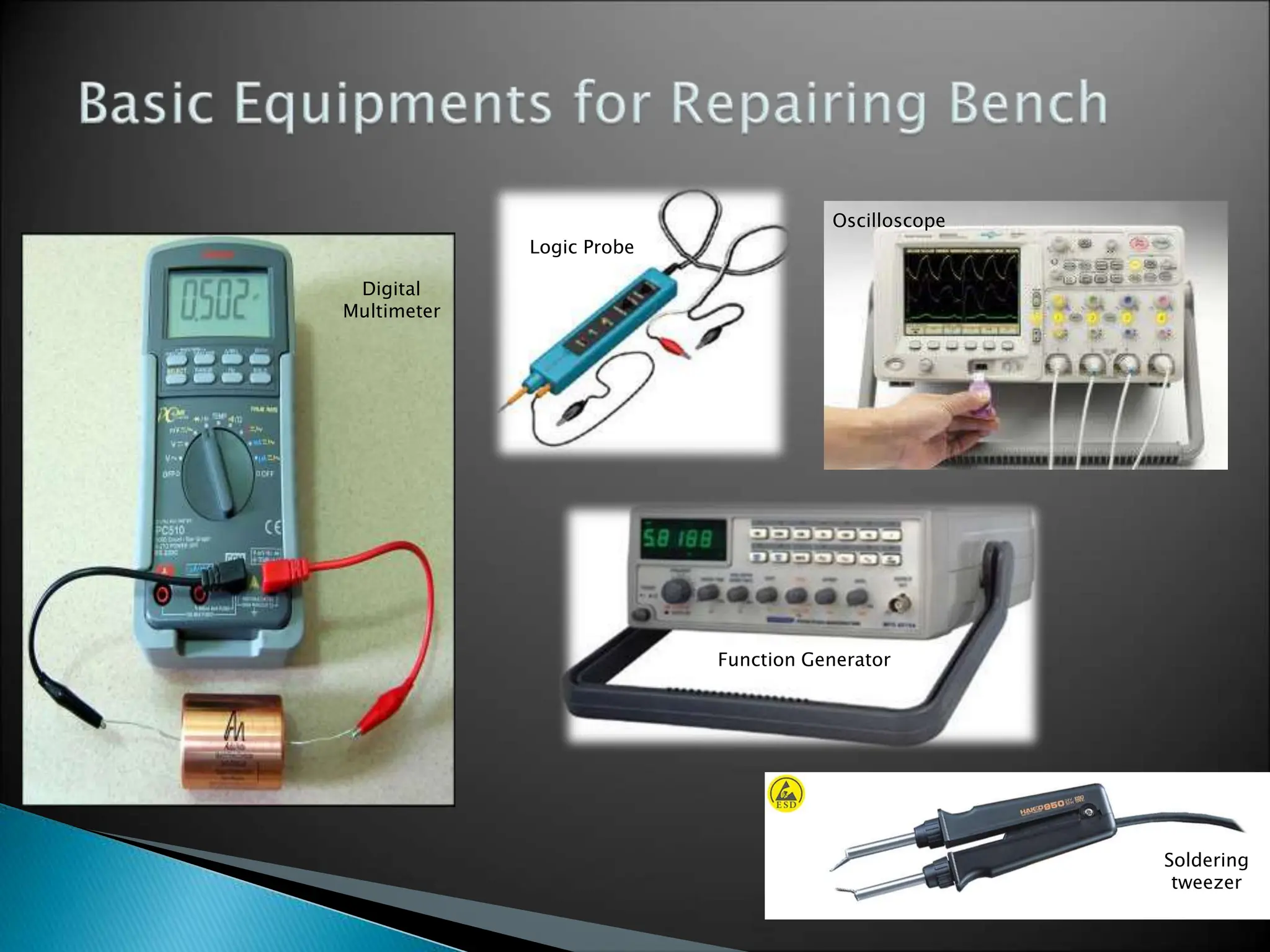
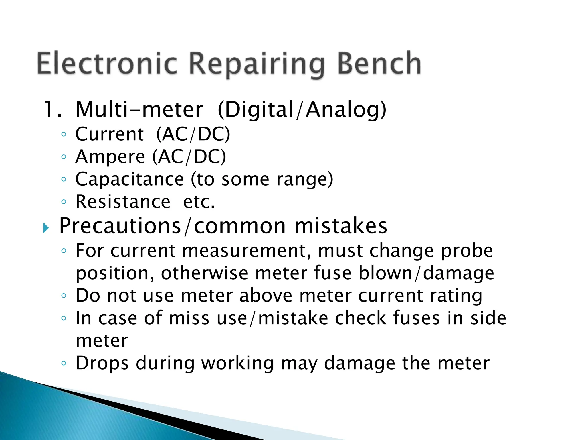
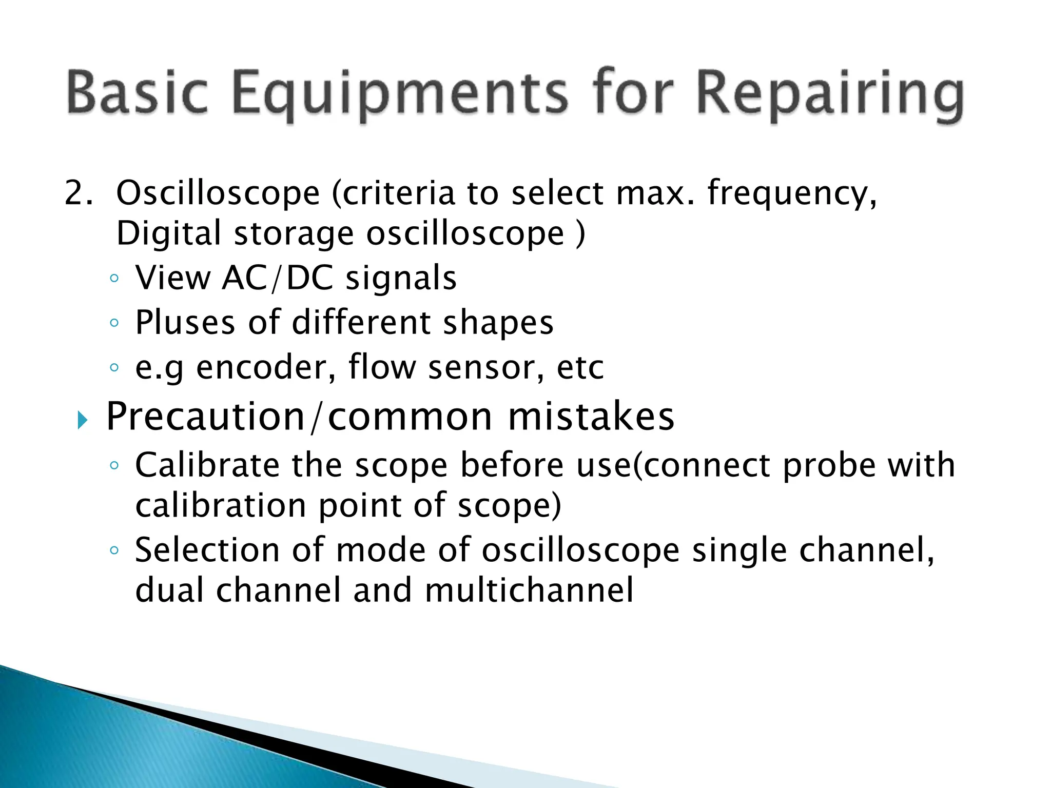
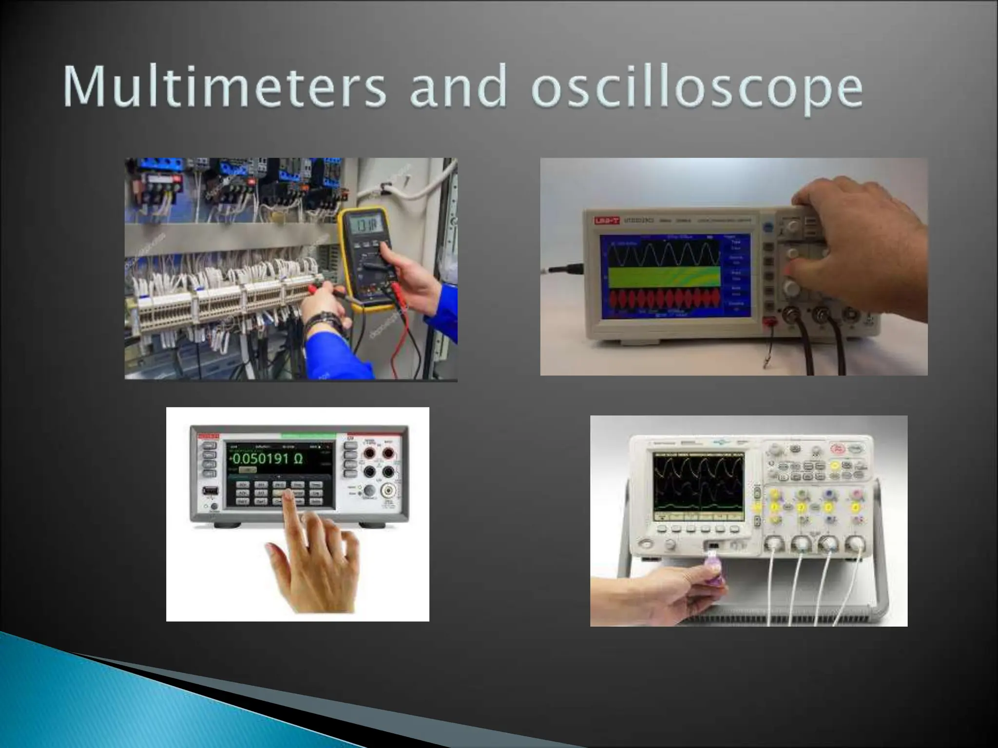
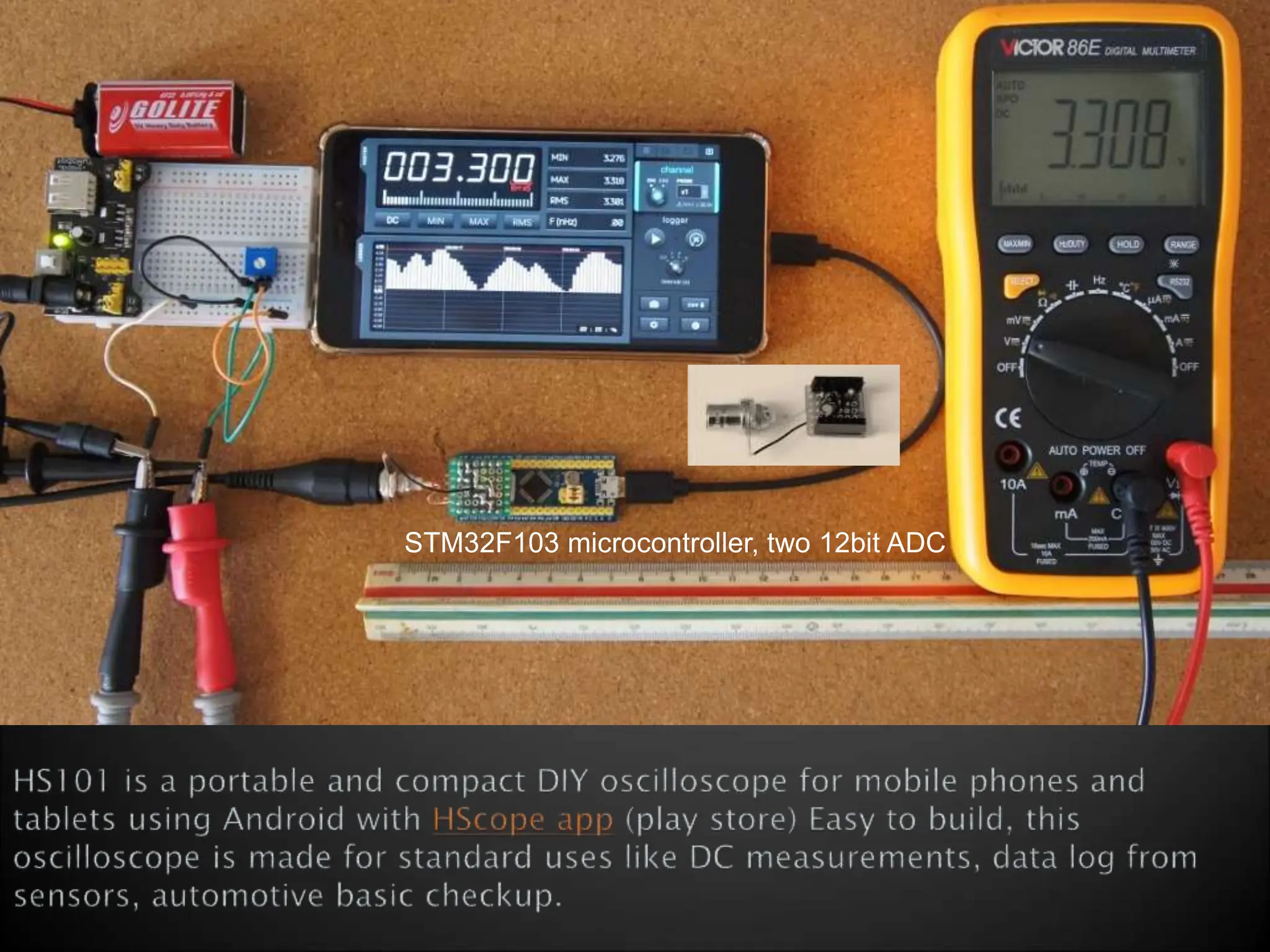
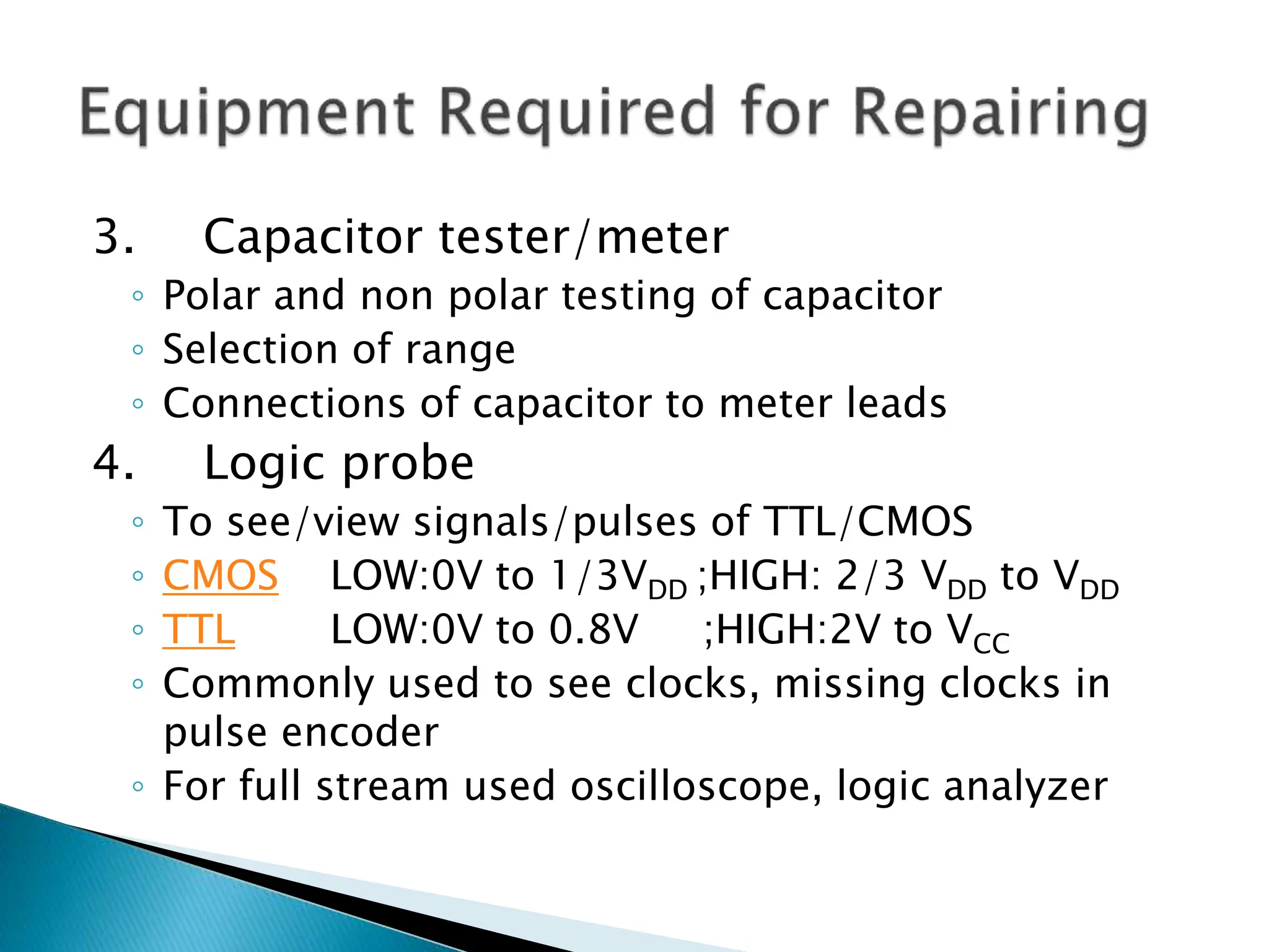
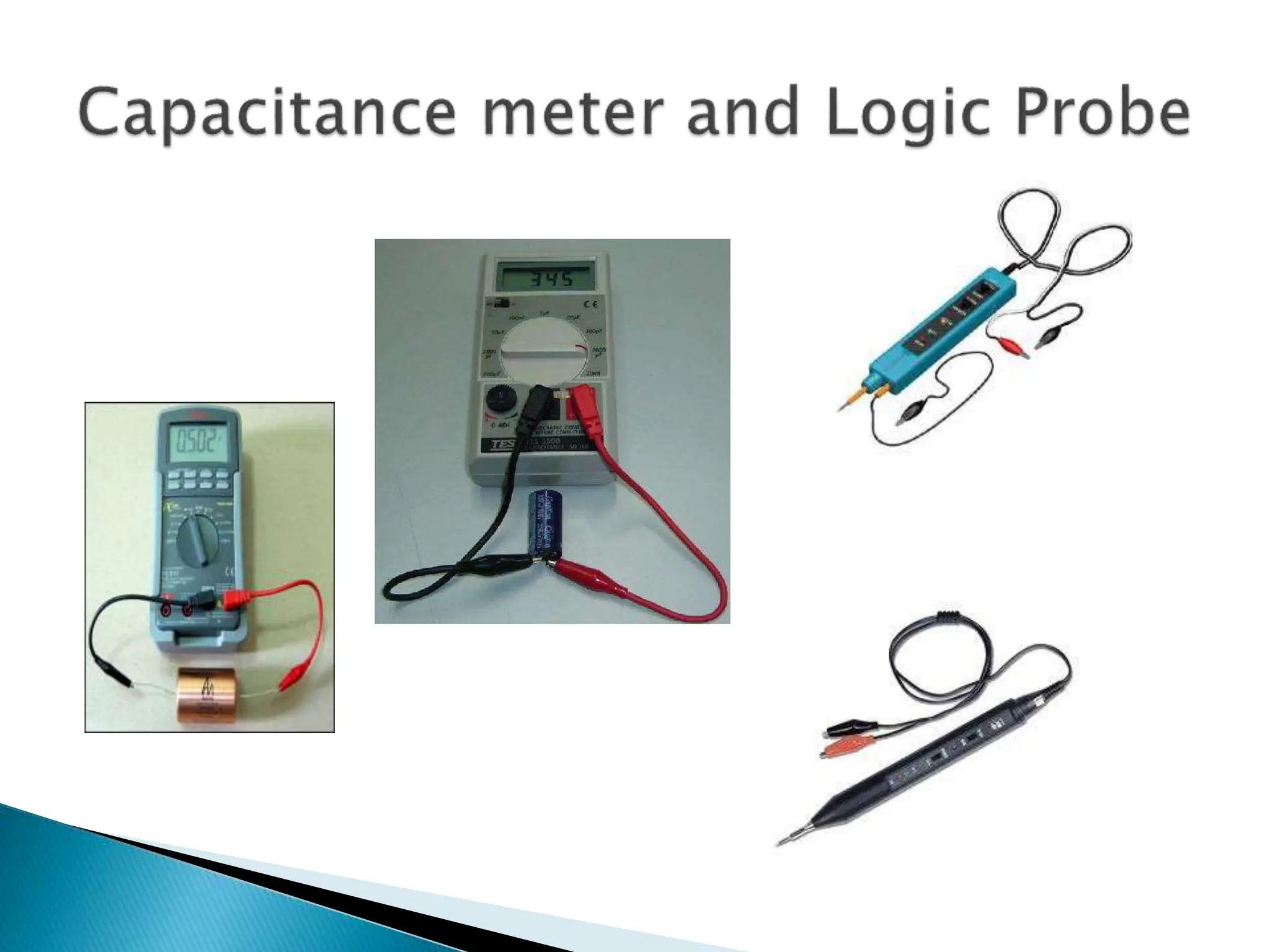
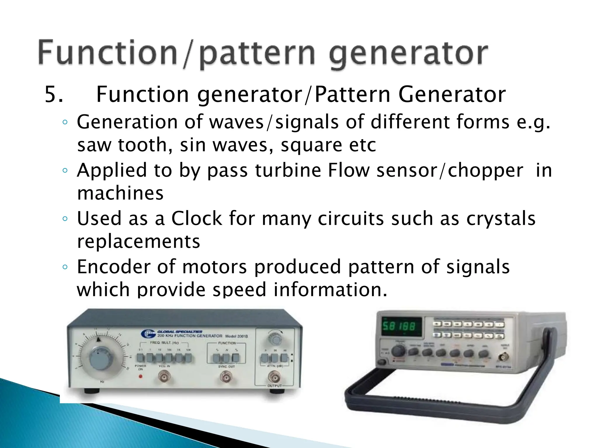
- Multi-meters, oscilloscopes, logic probes, and function generators for testing circuits.
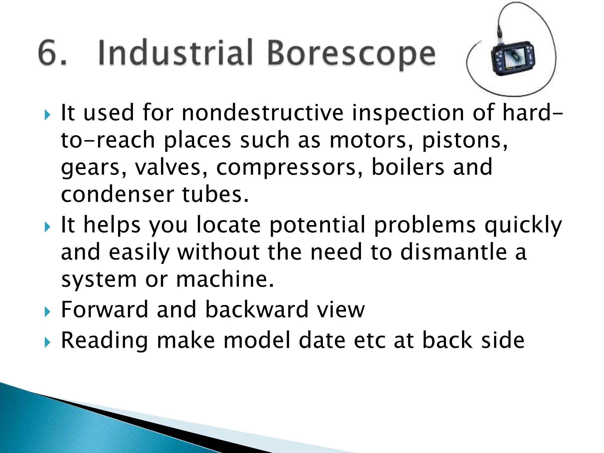
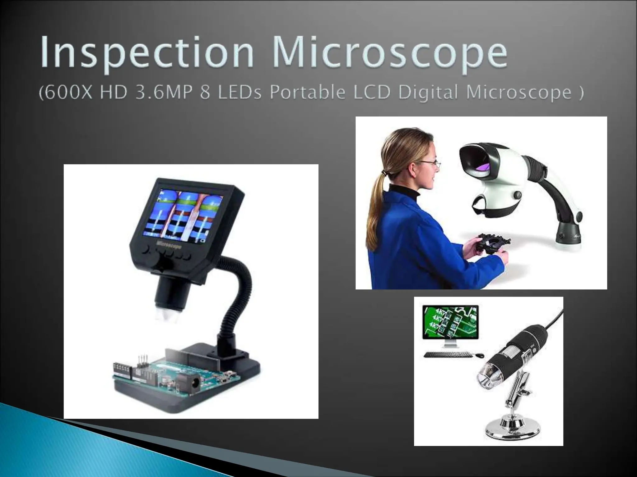
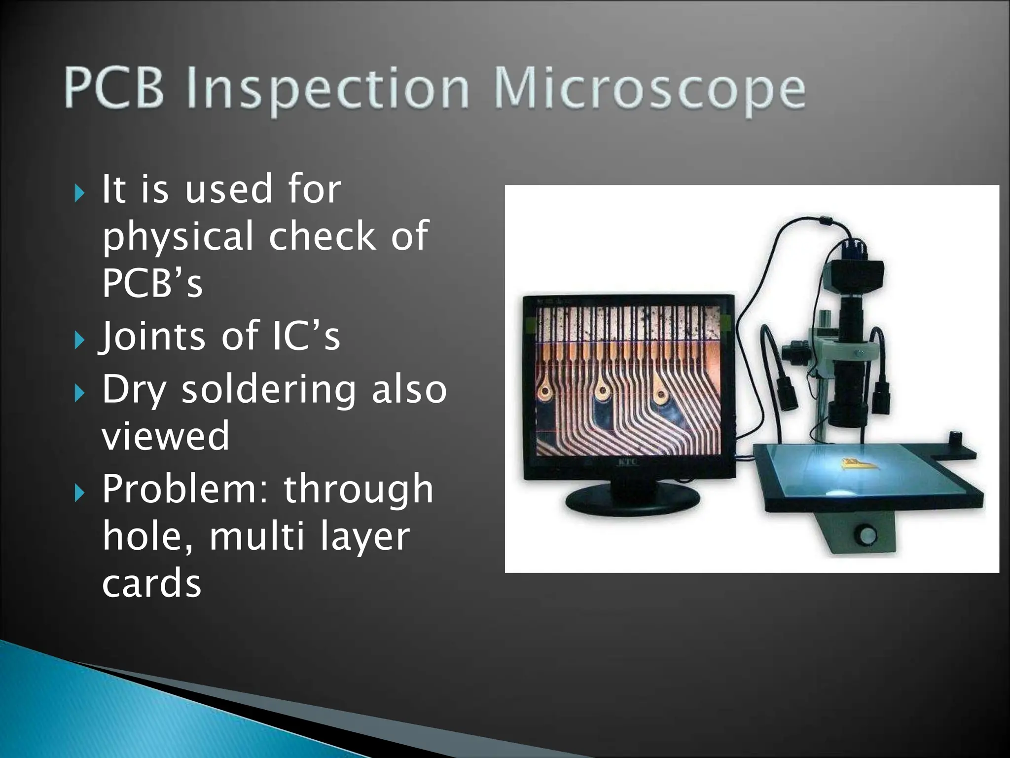
- Microscopes and borescopes for inspection.
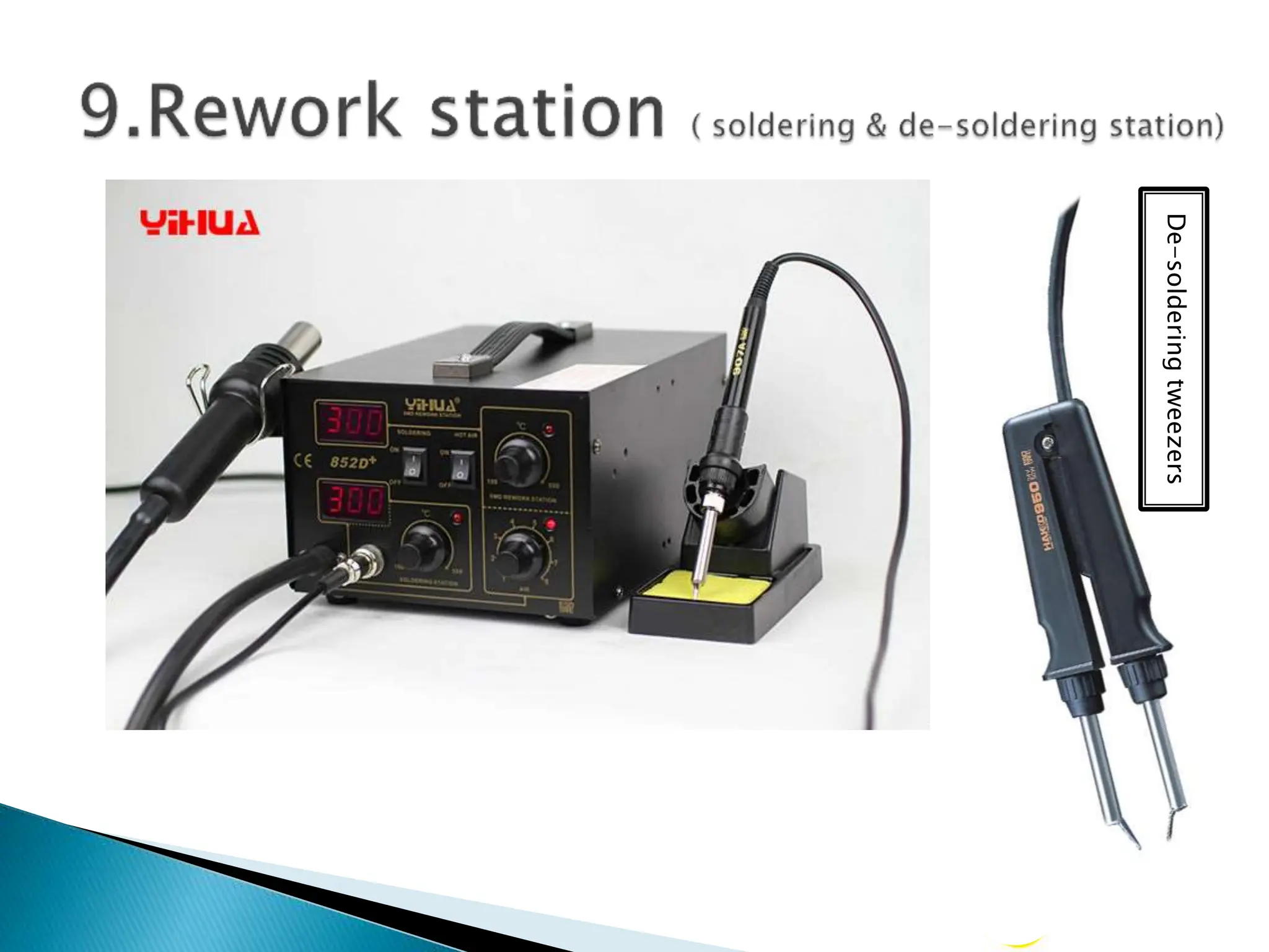
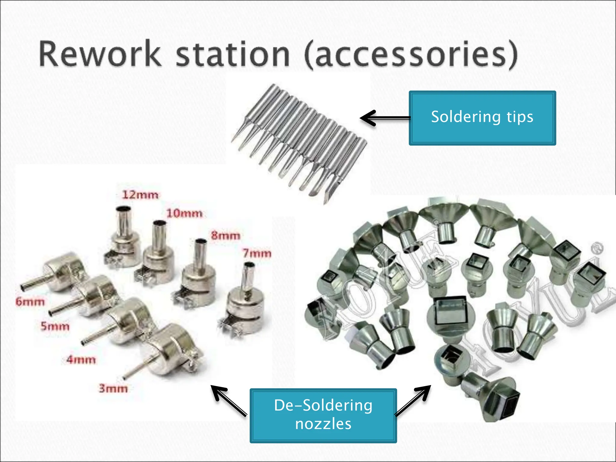
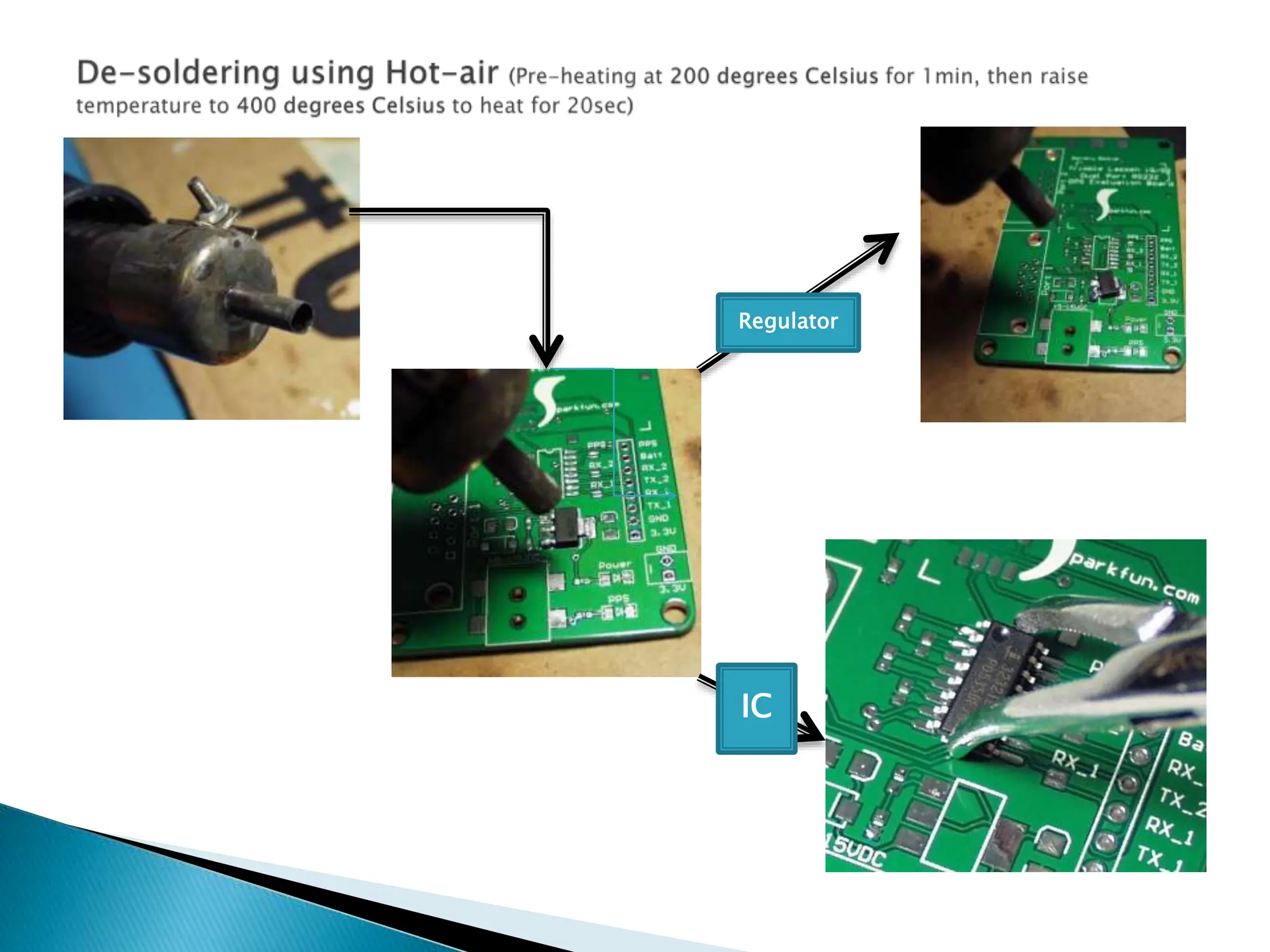
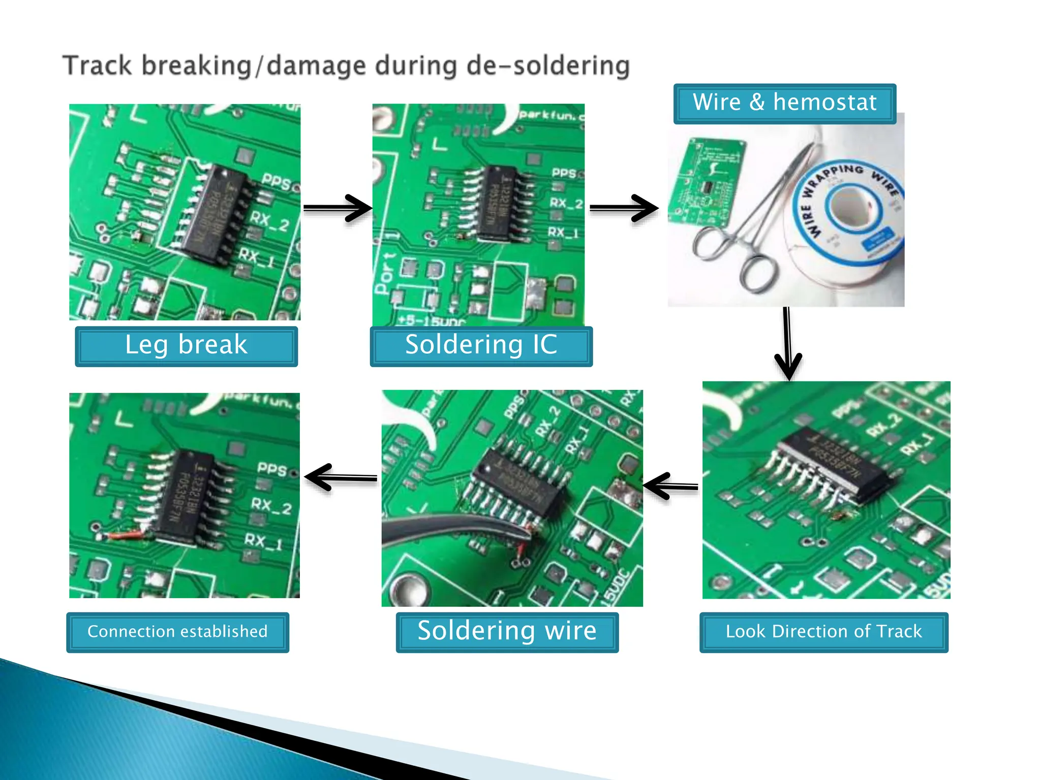
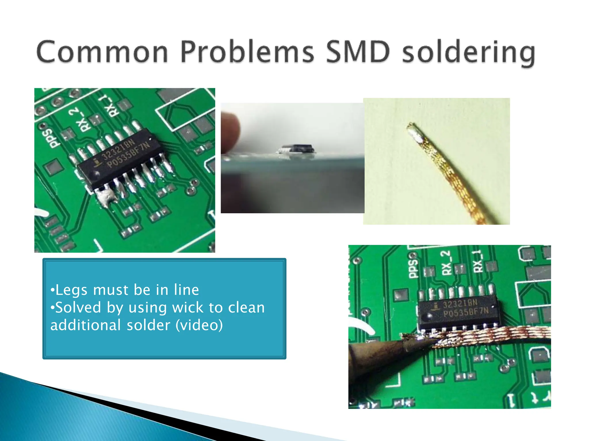
- Desoldering and soldering equipment for component-level repairs.
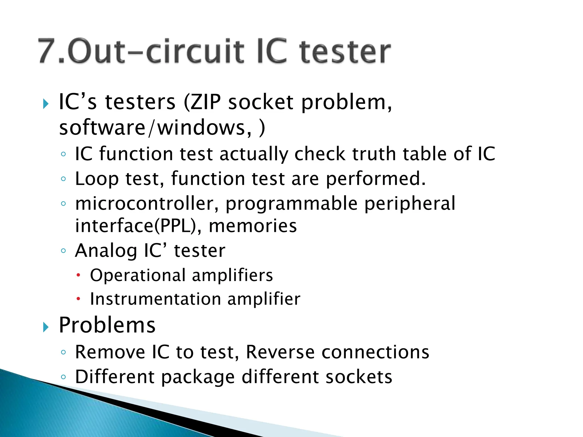
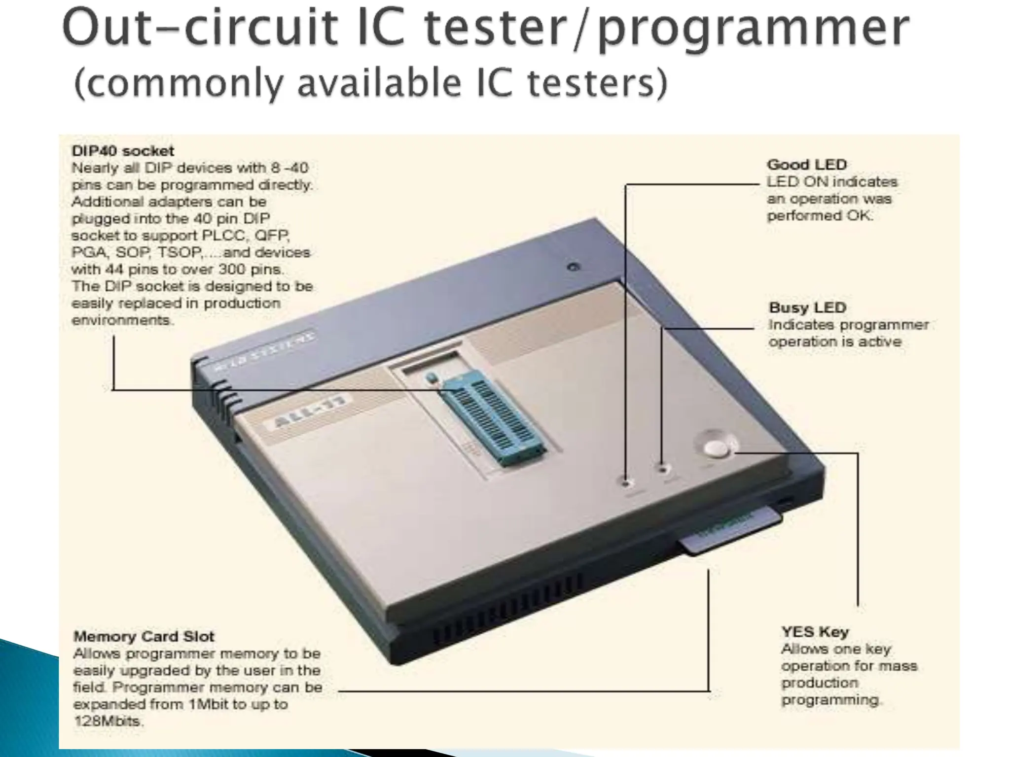
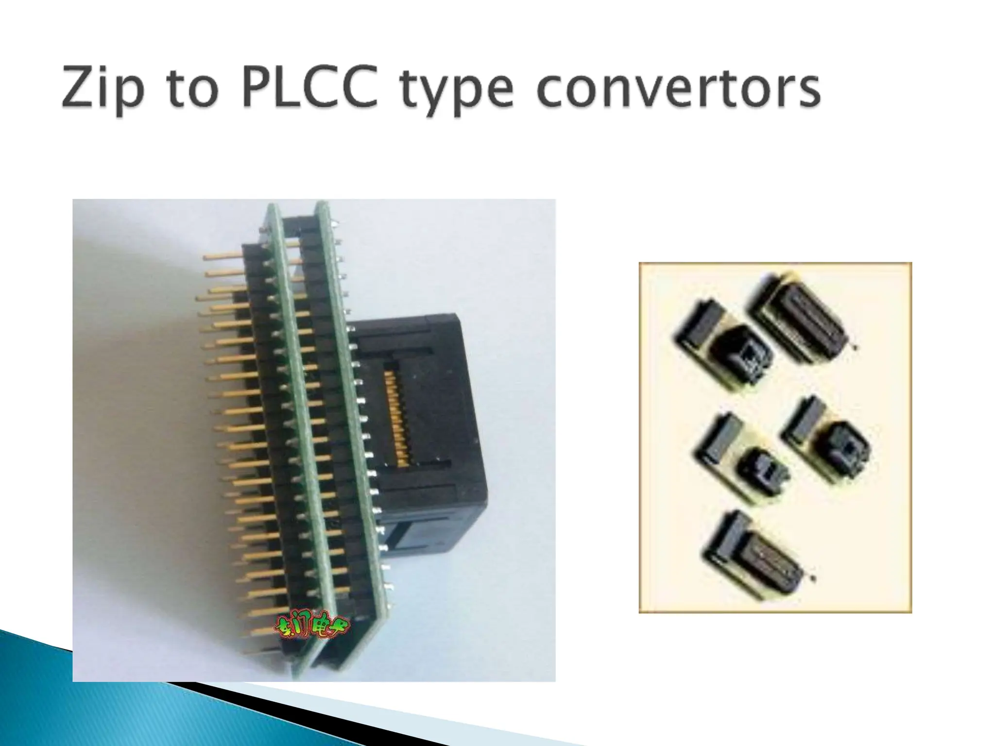
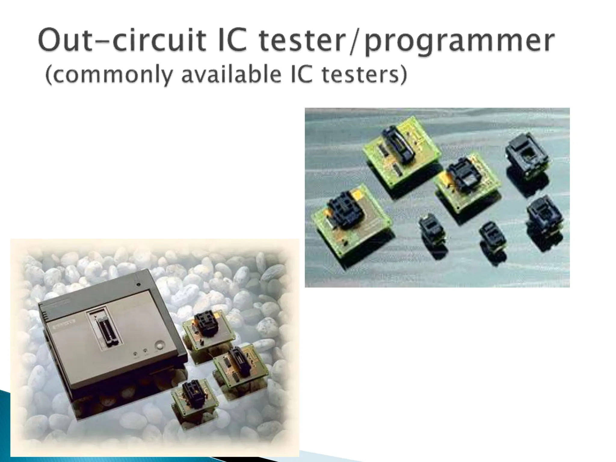
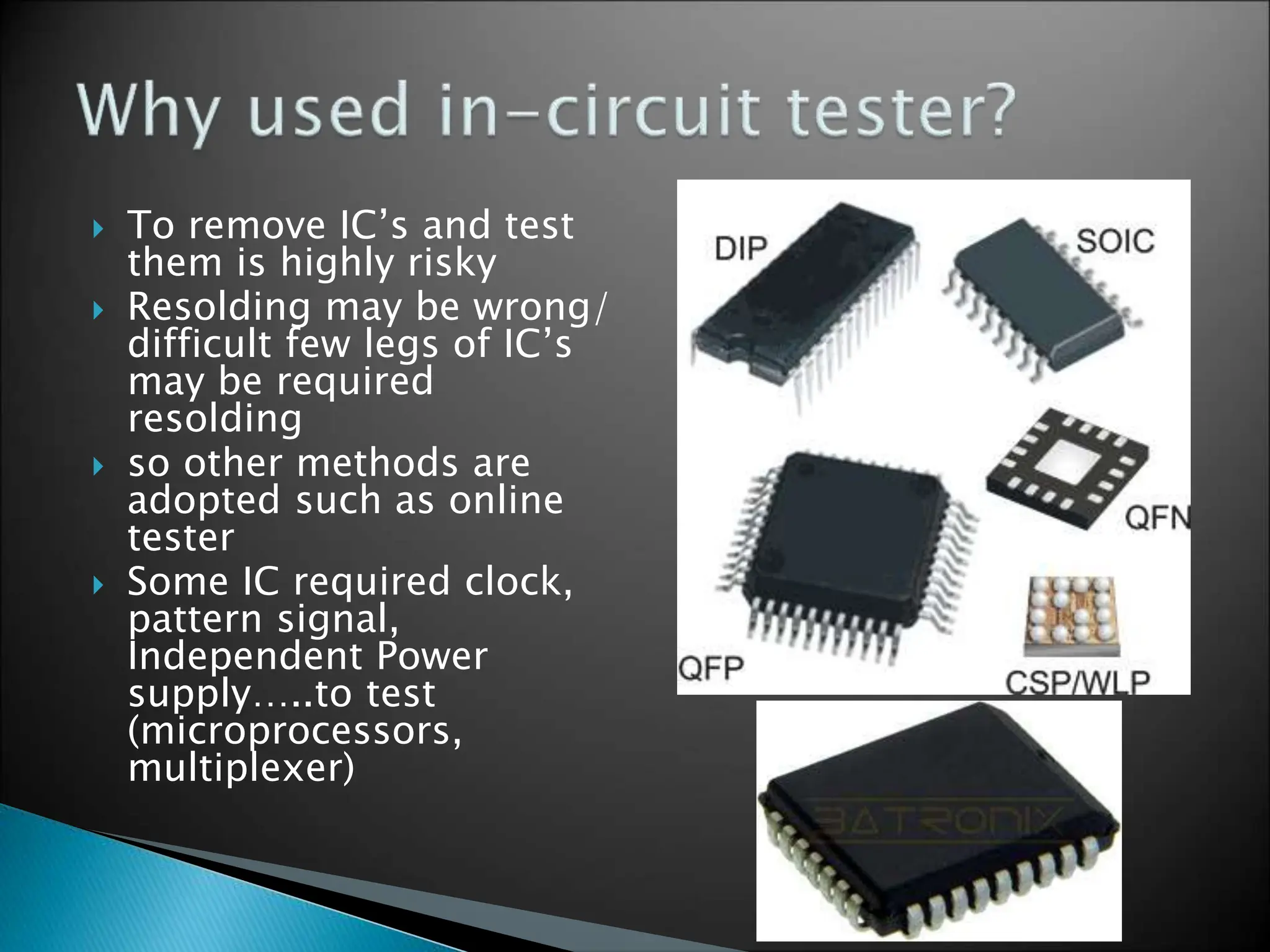
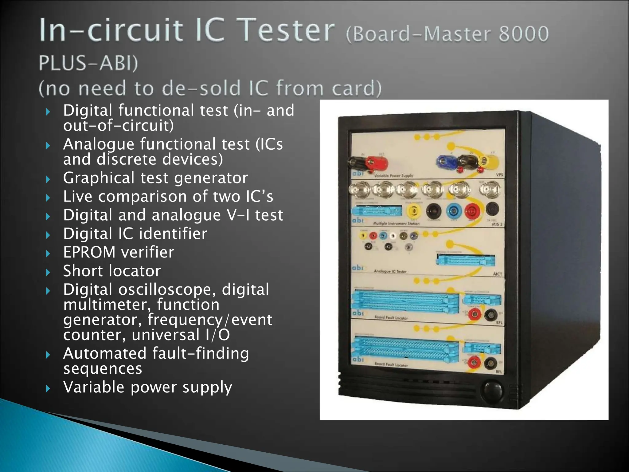
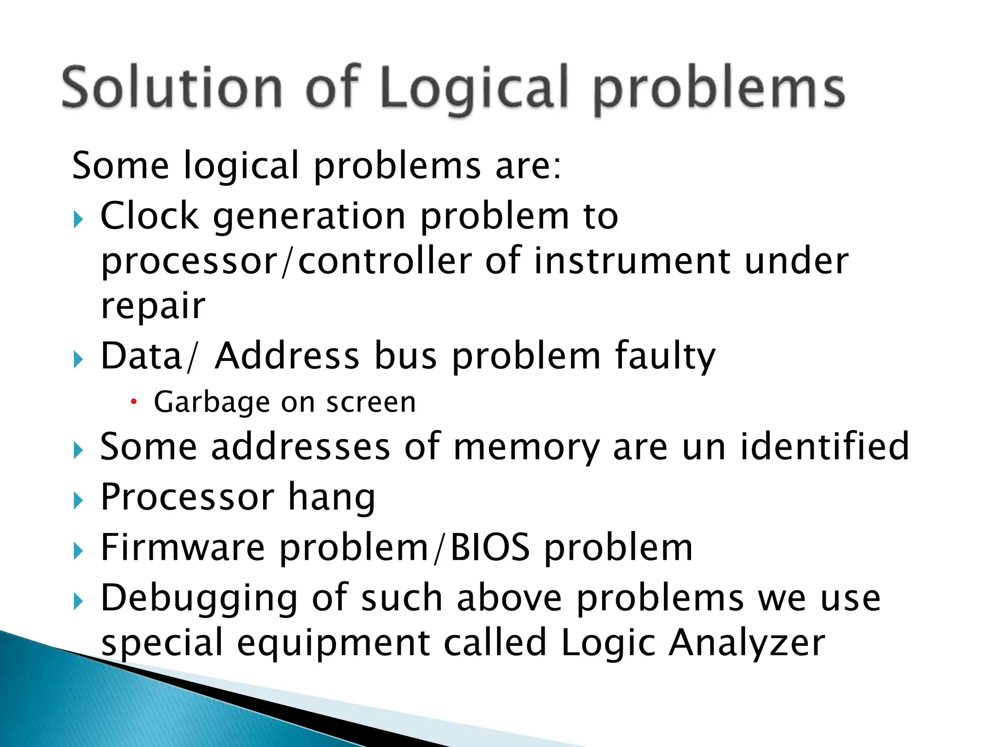
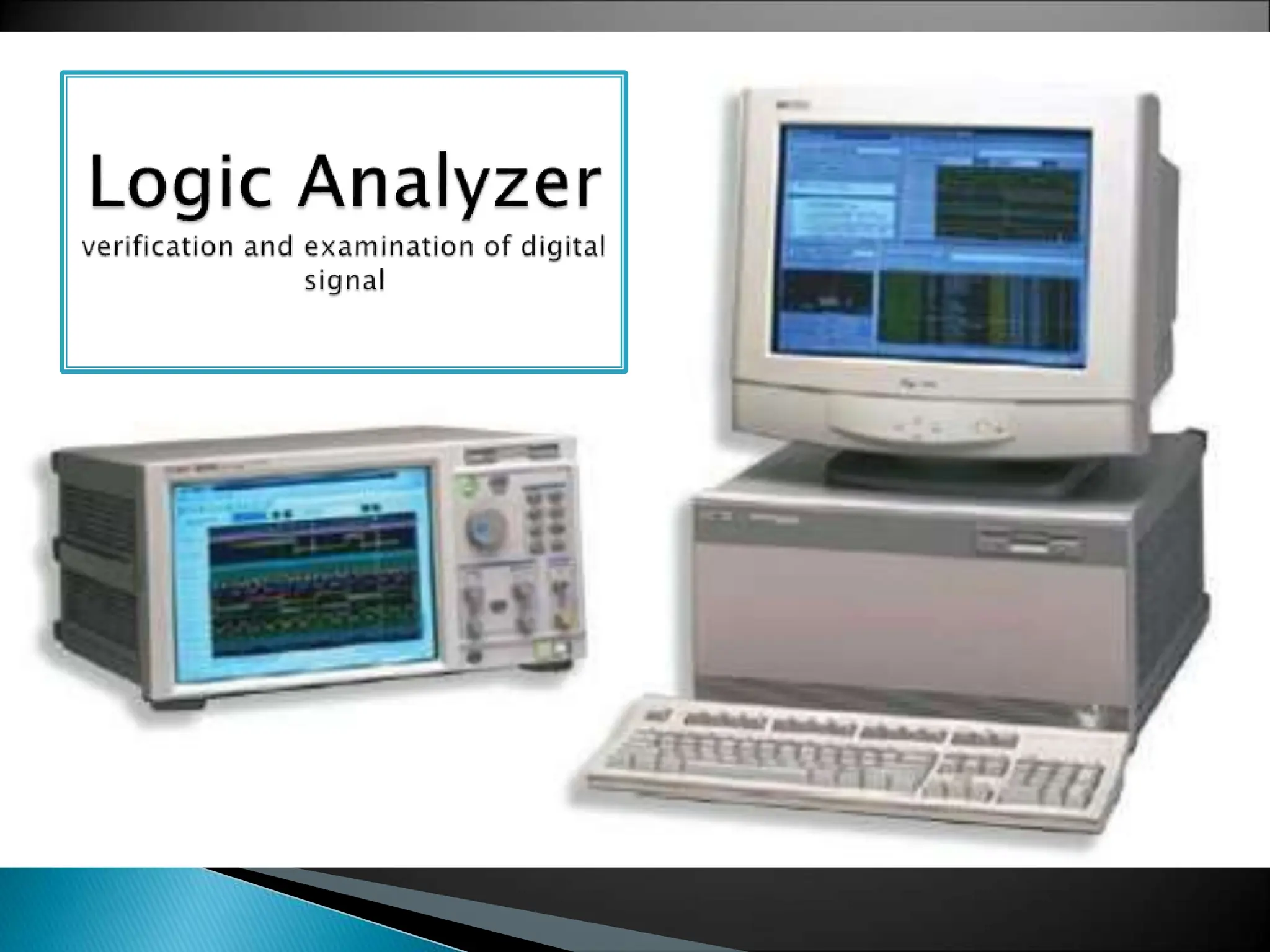
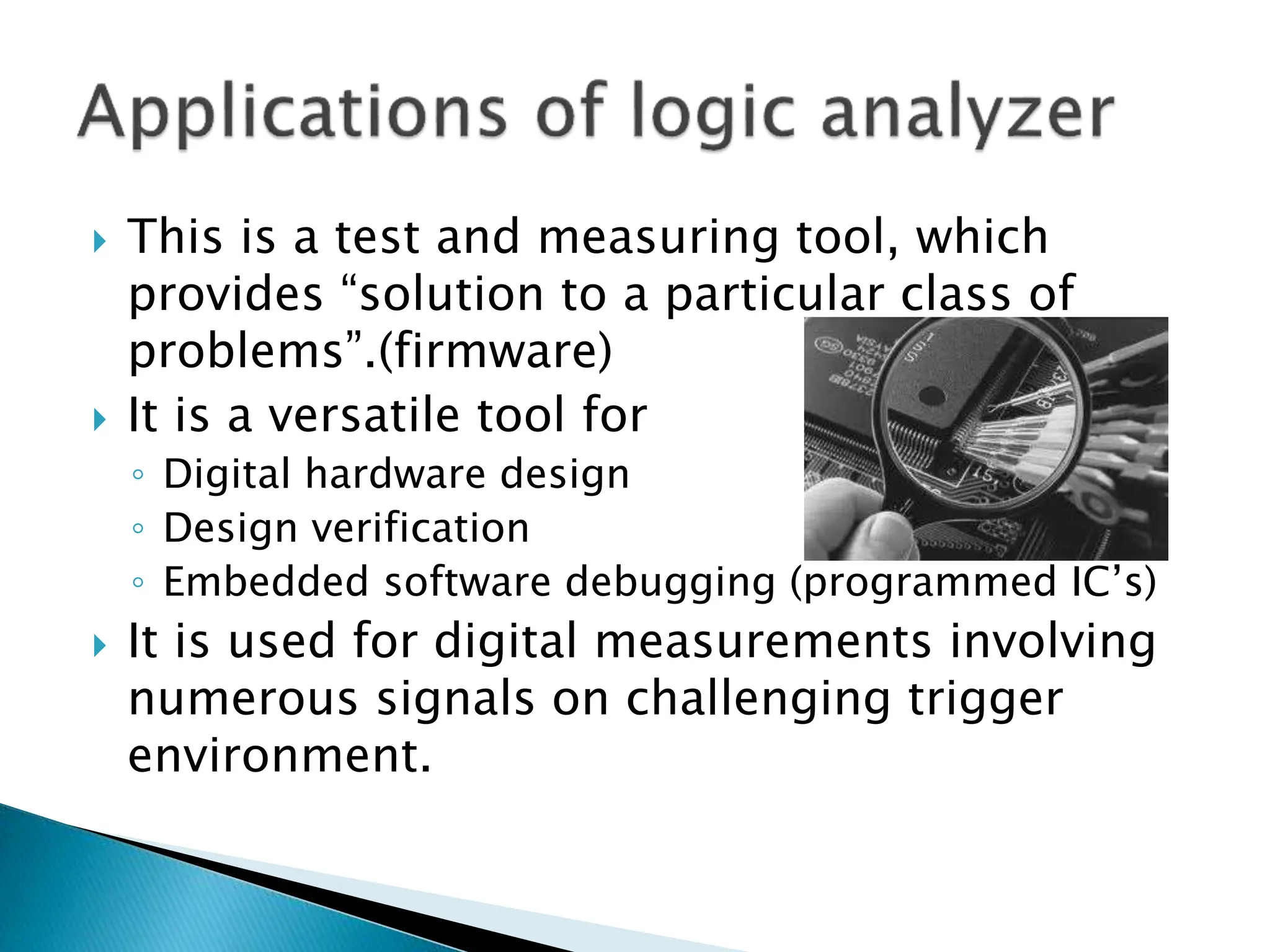
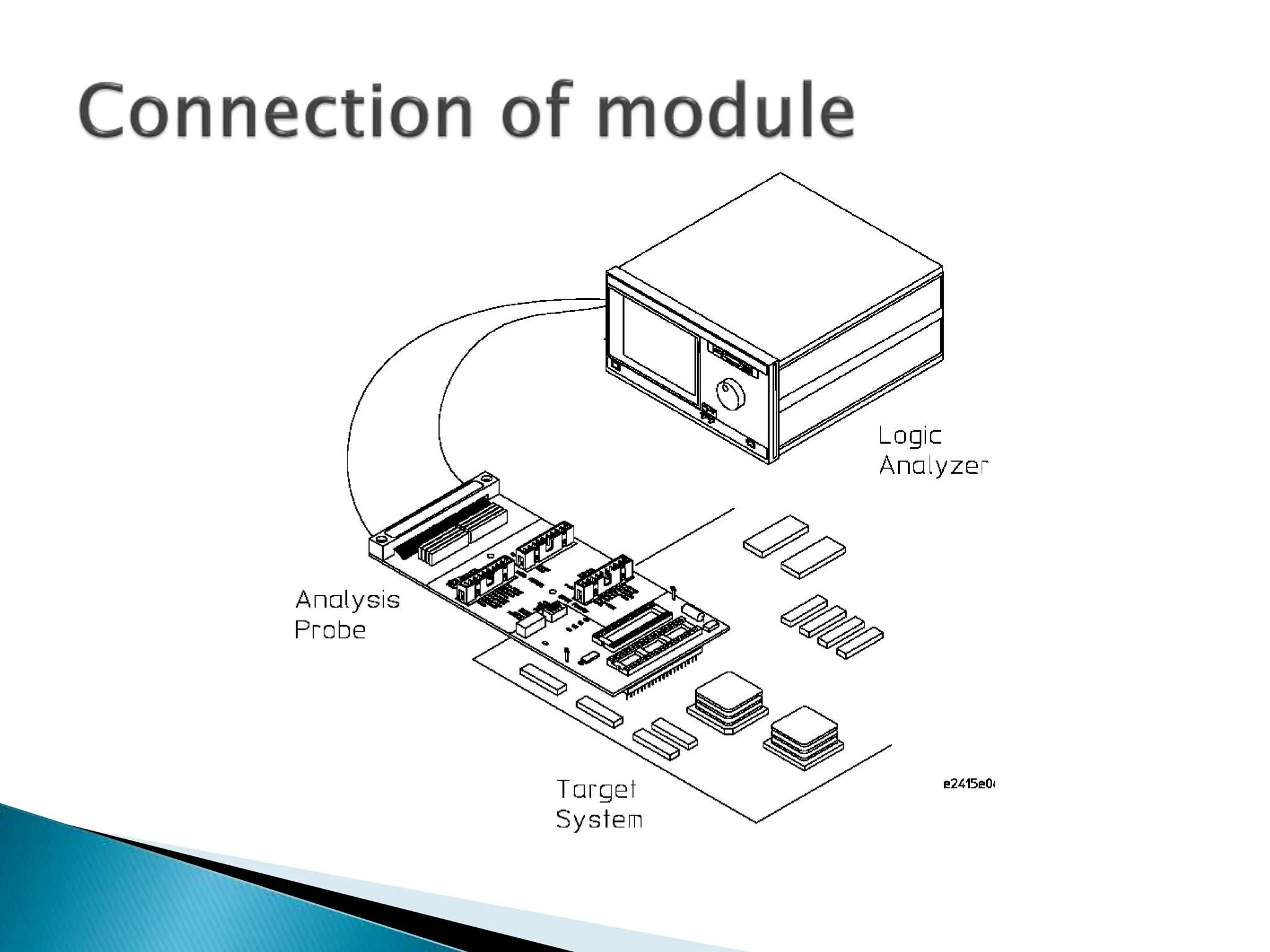
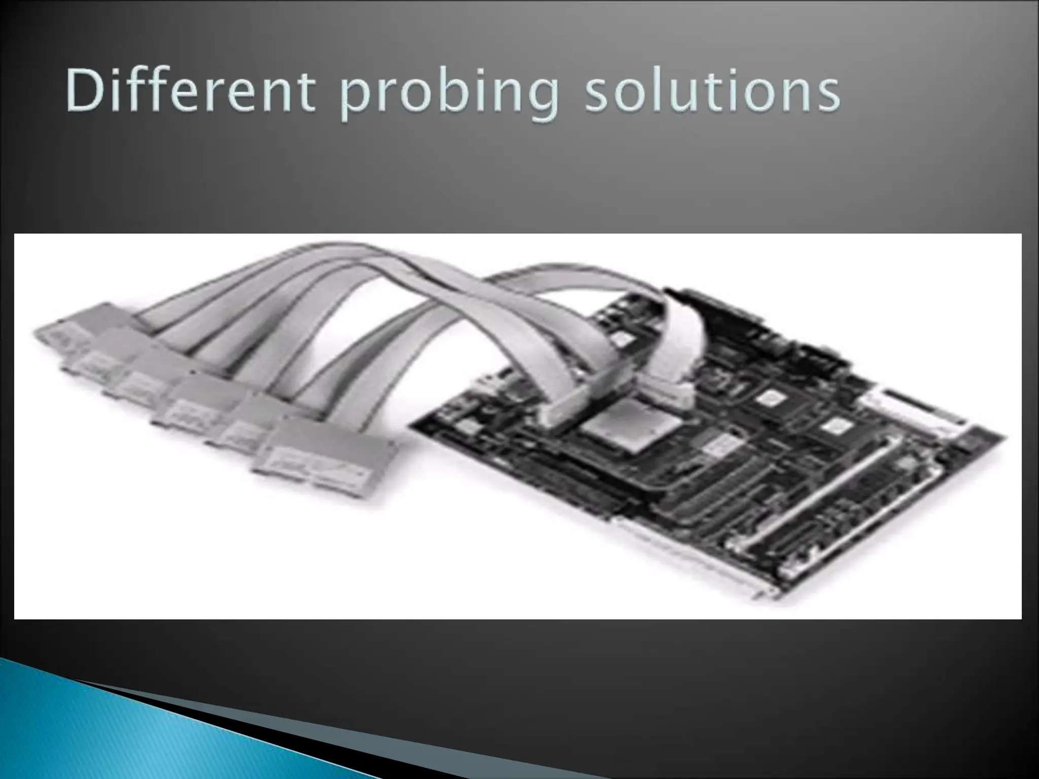
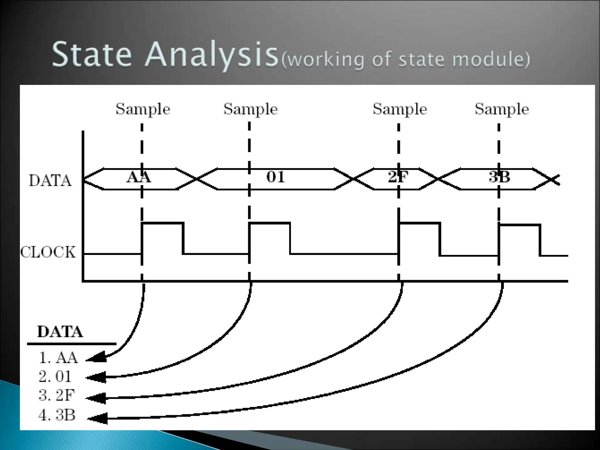
- In-circuit testers and logic analyzers for debugging logic problems.
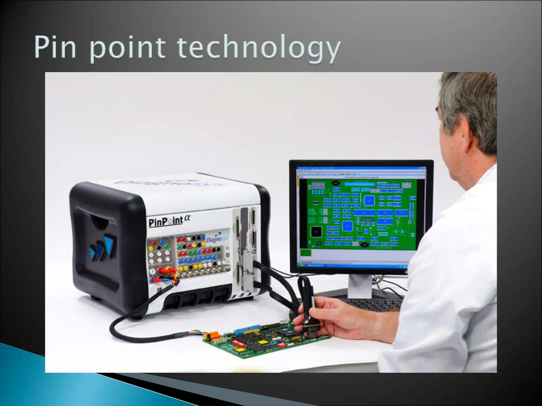
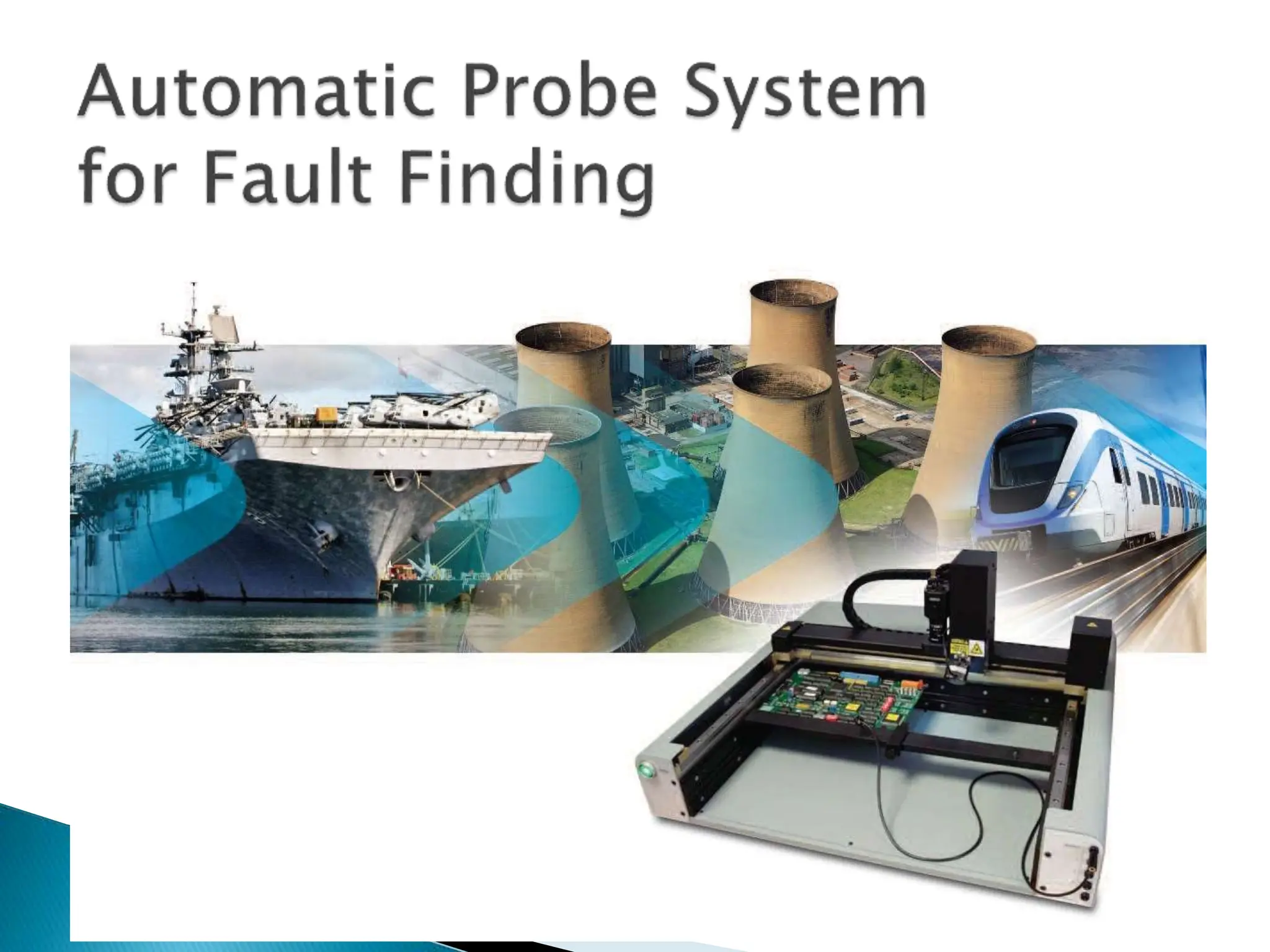
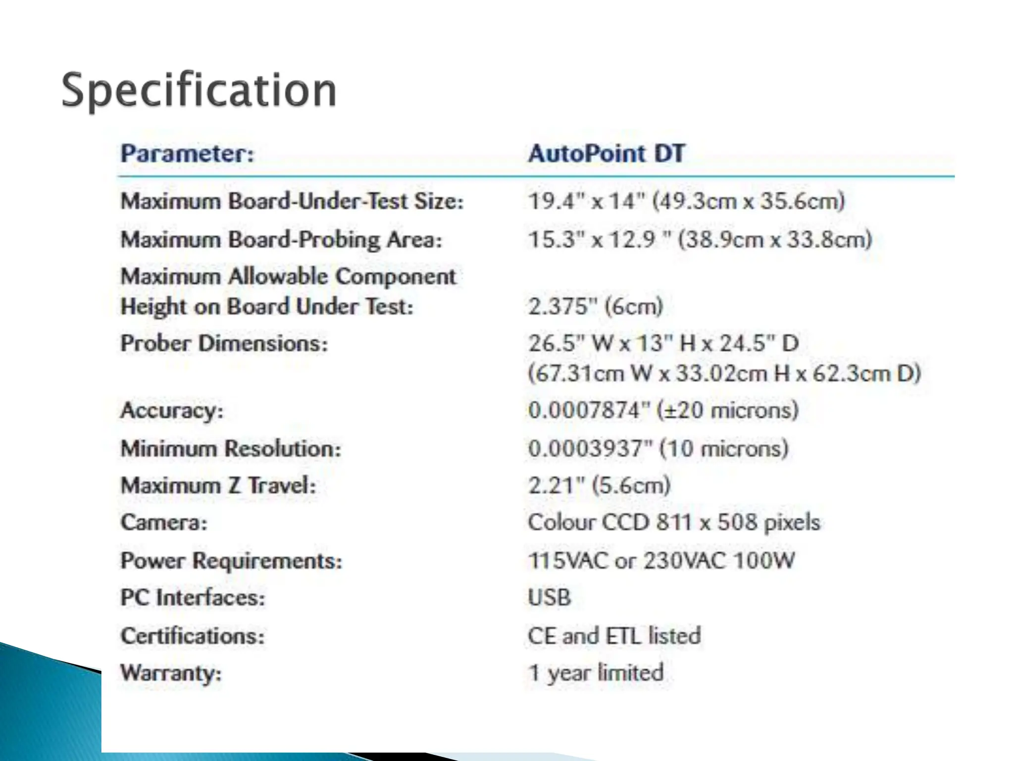
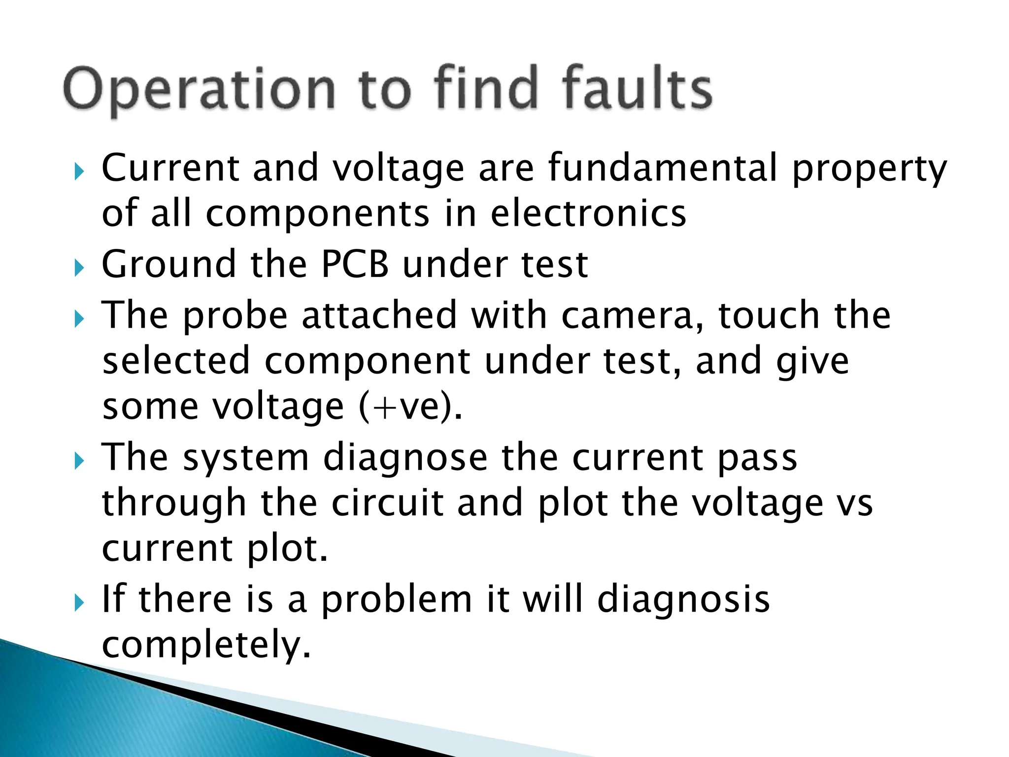
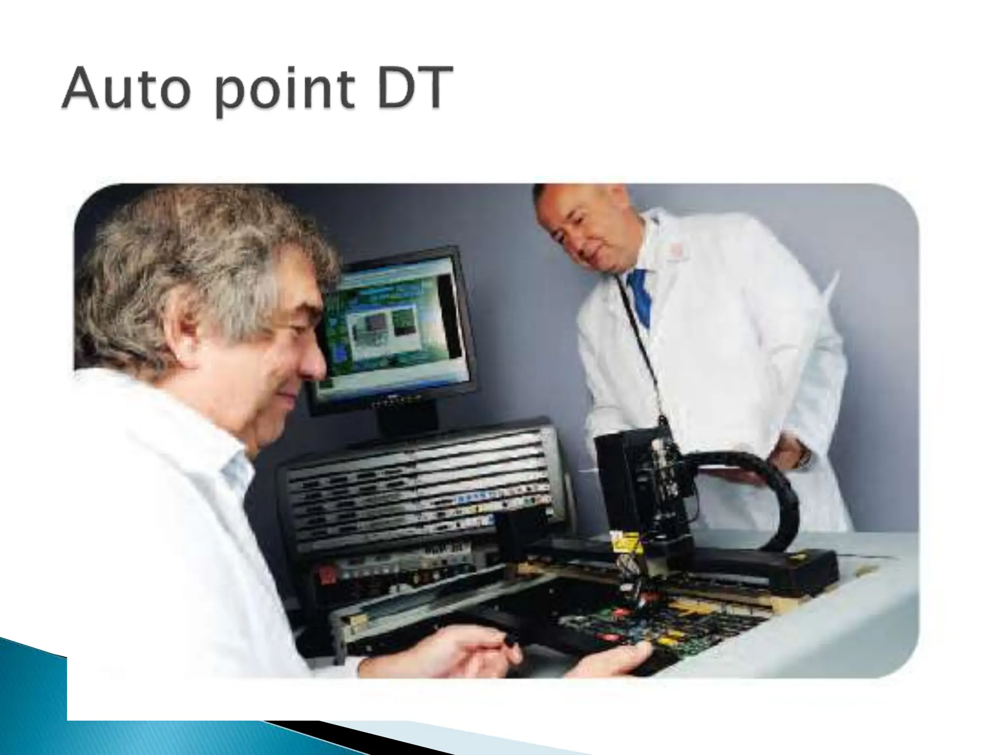
- Advanced techniques like pinpoint technology and auto-point DT for reverse engineering and fault isolation without schematics.
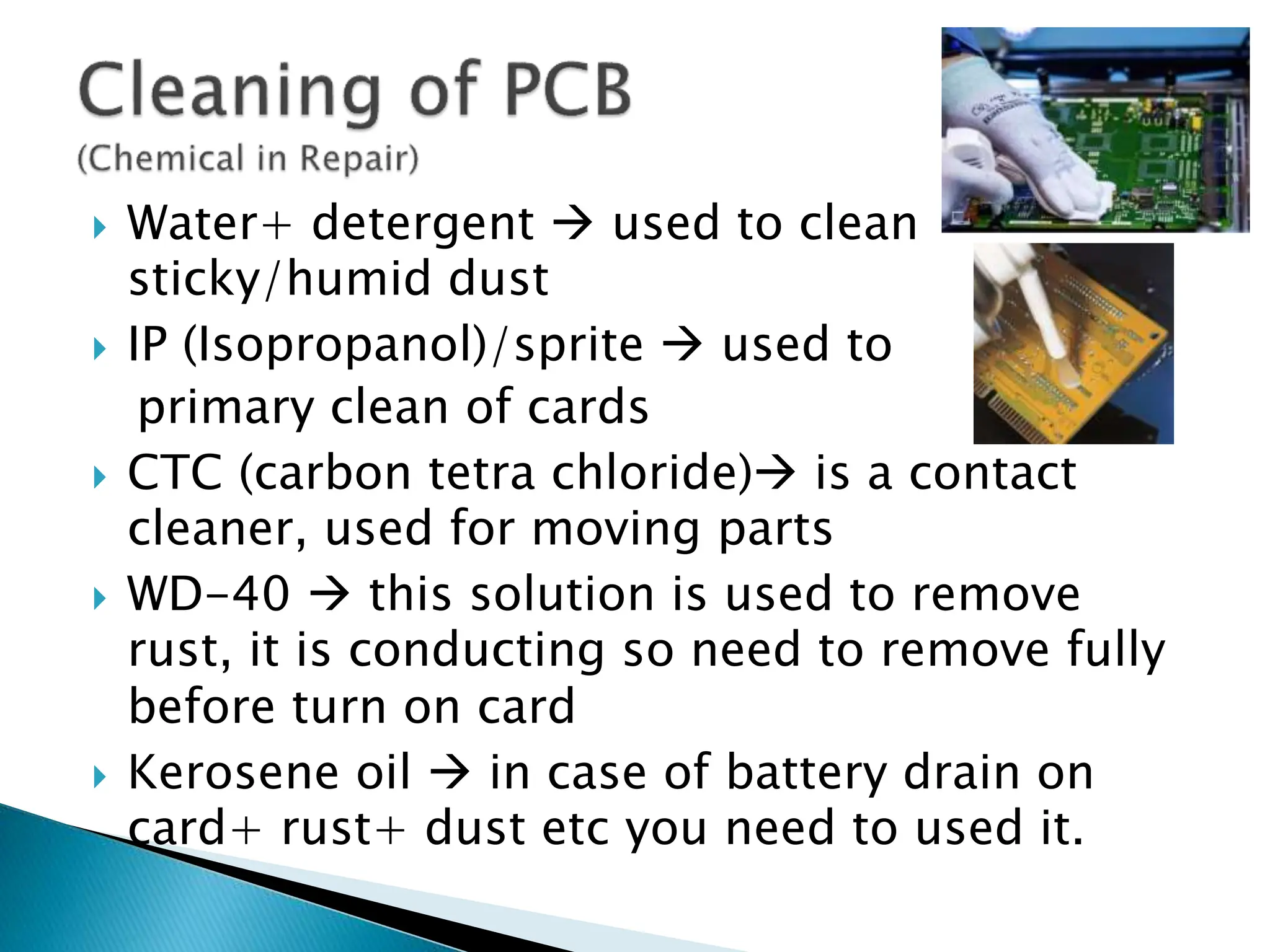
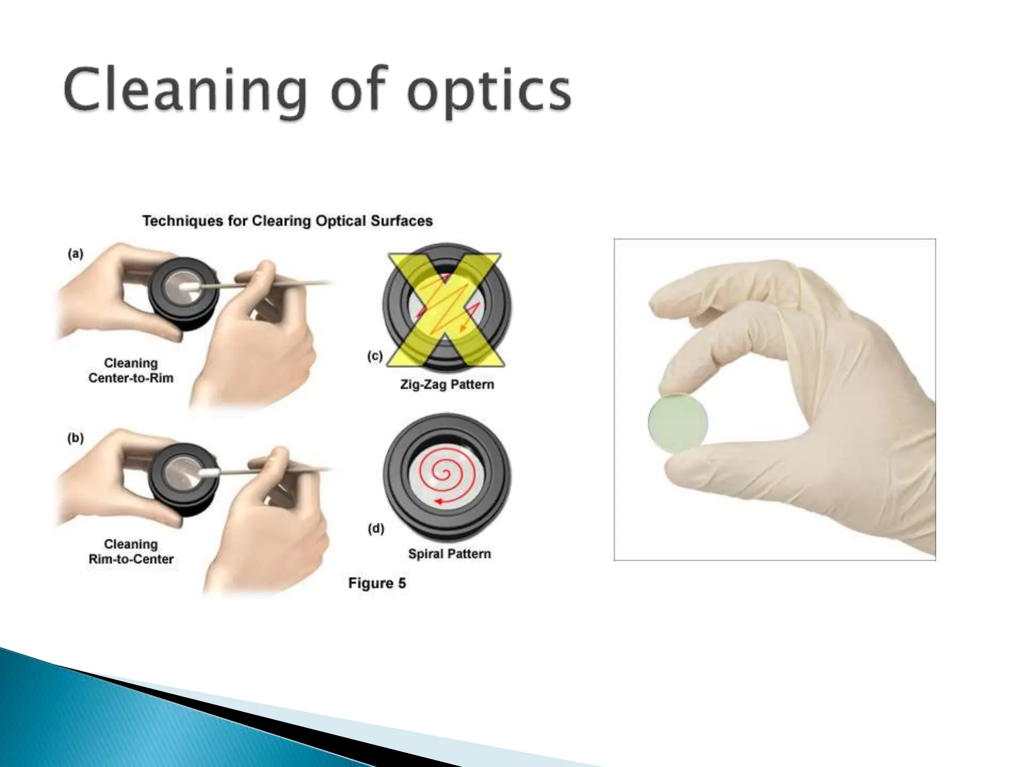
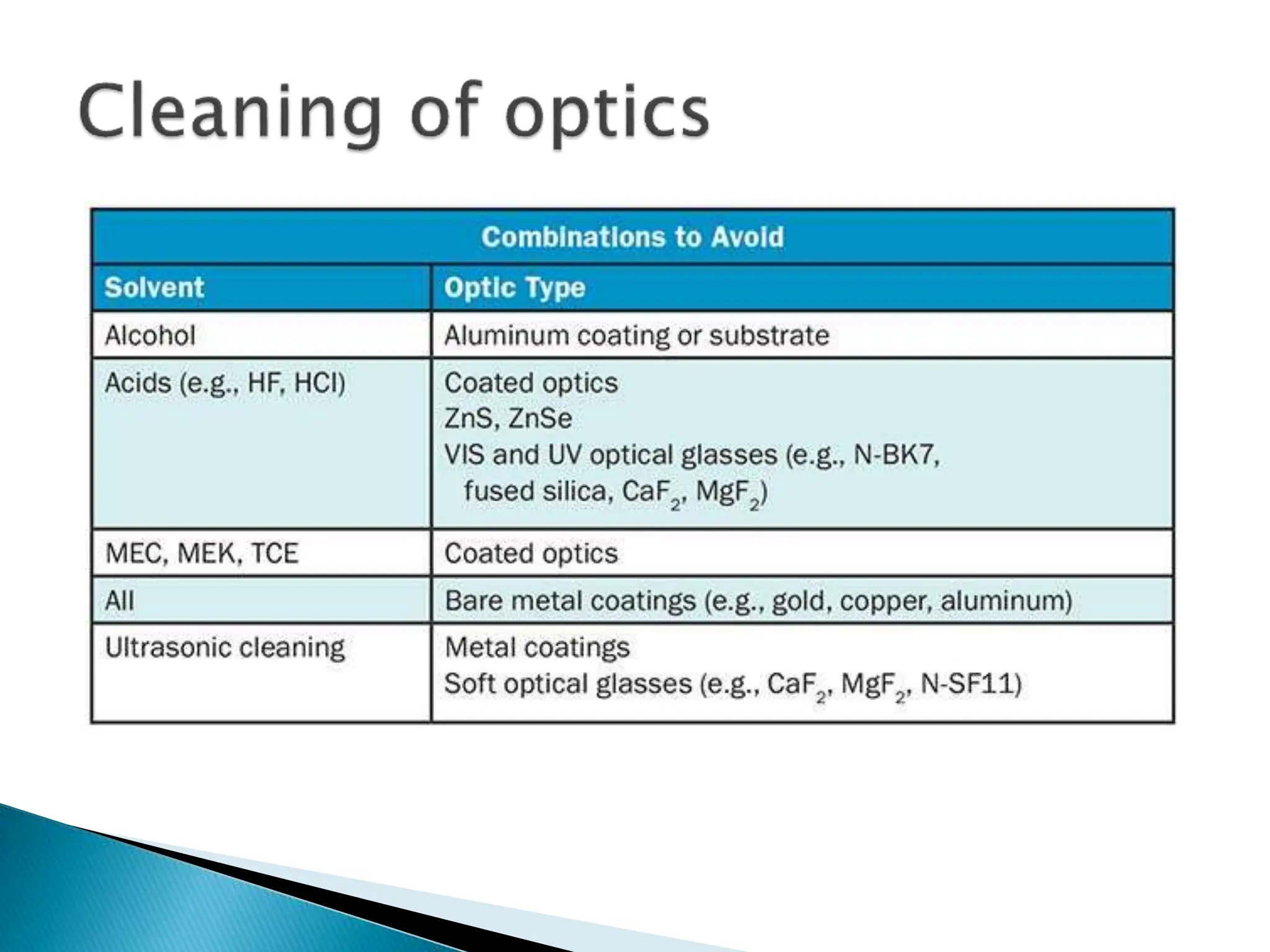
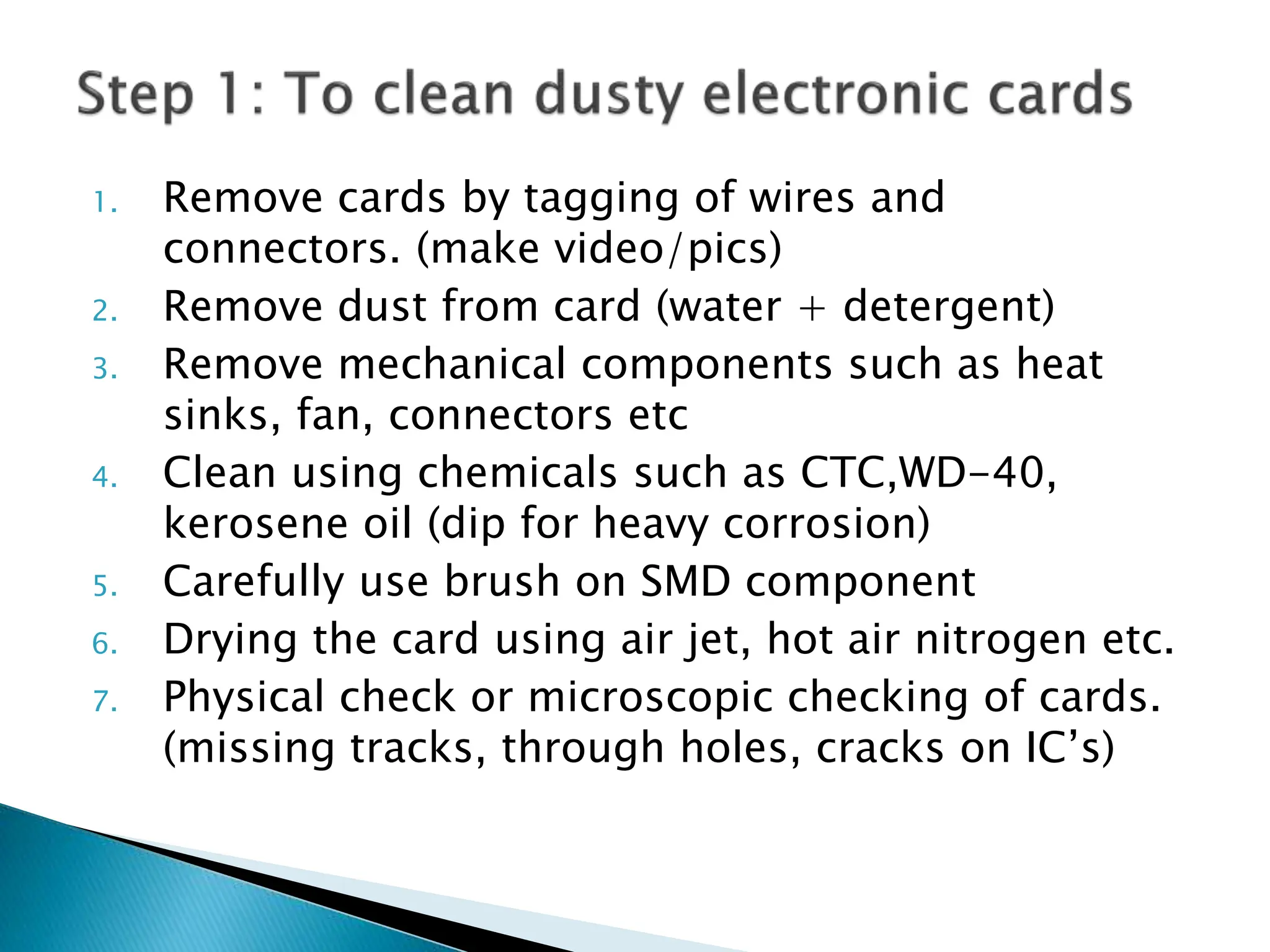
- Considerations for cleaning and maintenance of circuit boards.
Printed circuit board (PCB) functional tester performs critical validation process performed on manufactured PCBs to verify the board’s functionality meets the original design requirements and specifications. Thorough functional testing helps ensure the reliability and performance of PCBs before deployment.
Testing coverage-
Validate continuity and isolation: Verify electrical connectivity and isolation between traces using in-circuit testing (ICT) and flying probe testing to check for opens and shorts.
Confirm impedance: Match measured impedance of traces and interconnects to design values to prevent signal degradation.
Verify power integrity: Check PCB operation under different power conditions to avoid errors from insufficient power delivery.
Assess signal integrity: Examine signal quality under high-speed conditions to prevent distortion and interference.
Test functionality: Stimulate the PCB with input signals and power to check outputs match expected responses based on design.
Confirm robustness: Subject PCB to temperature cycling, vibration, shock to validate resilience and durability.
Execute regression testing: Retest functionality after modifications to ensure no side effects.
This PPT gives information about:
1. Introduction to Architecture and features of 8051 Microcontrollers..
2. Specifications (with package detail), Instruction set / Bus architecture, RAM, FLASH, UART and other peripherals, Interrupts, timer, Counters,..
3. Software: Writing C programs, Compiling, Linking and Simulating these programs, bootloader, burning the hex file in Rom of Microcontroller.
Automobile Management System Project Report.pdfKamal Acharya
The proposed project is developed to manage the automobile in the automobile dealer company. The main module in this project is login, automobile management, customer management, sales, complaints and reports. The first module is the login. The automobile showroom owner should login to the project for usage. The username and password are verified and if it is correct, next form opens. If the username and password are not correct, it shows the error message.
When a customer search for a automobile, if the automobile is available, they will be taken to a page that shows the details of the automobile including automobile name, automobile ID, quantity, price etc. “Automobile Management System” is useful for maintaining automobiles, customers effectively and hence helps for establishing good relation between customer and automobile organization. It contains various customized modules for effectively maintaining automobiles and stock information accurately and safely.
When the automobile is sold to the customer, stock will be reduced automatically. When a new purchase is made, stock will be increased automatically. While selecting automobiles for sale, the proposed software will automatically check for total number of available stock of that particular item, if the total stock of that particular item is less than 5, software will notify the user to purchase the particular item.
Also when the user tries to sale items which are not in stock, the system will prompt the user that the stock is not enough. Customers of this system can search for a automobile; can purchase a automobile easily by selecting fast. On the other hand the stock of automobiles can be maintained perfectly by the automobile shop manager overcoming the drawbacks of existing system.
CFD Simulation of By-pass Flow in a HRSG module by R&R Consult.pptxR&R Consult
CFD analysis is incredibly effective at solving mysteries and improving the performance of complex systems!
Here's a great example: At a large natural gas-fired power plant, where they use waste heat to generate steam and energy, they were puzzled that their boiler wasn't producing as much steam as expected.
R&R and Tetra Engineering Group Inc. were asked to solve the issue with reduced steam production.
An inspection had shown that a significant amount of hot flue gas was bypassing the boiler tubes, where the heat was supposed to be transferred.
R&R Consult conducted a CFD analysis, which revealed that 6.3% of the flue gas was bypassing the boiler tubes without transferring heat. The analysis also showed that the flue gas was instead being directed along the sides of the boiler and between the modules that were supposed to capture the heat. This was the cause of the reduced performance.
Based on our results, Tetra Engineering installed covering plates to reduce the bypass flow. This improved the boiler's performance and increased electricity production.
It is always satisfying when we can help solve complex challenges like this. Do your systems also need a check-up or optimization? Give us a call!
Work done in cooperation with James Malloy and David Moelling from Tetra Engineering.
More examples of our work https://www.r-r-consult.dk/en/cases-en/
Explore the innovative world of trenchless pipe repair with our comprehensive guide, "The Benefits and Techniques of Trenchless Pipe Repair." This document delves into the modern methods of repairing underground pipes without the need for extensive excavation, highlighting the numerous advantages and the latest techniques used in the industry.
Learn about the cost savings, reduced environmental impact, and minimal disruption associated with trenchless technology. Discover detailed explanations of popular techniques such as pipe bursting, cured-in-place pipe (CIPP) lining, and directional drilling. Understand how these methods can be applied to various types of infrastructure, from residential plumbing to large-scale municipal systems.
Ideal for homeowners, contractors, engineers, and anyone interested in modern plumbing solutions, this guide provides valuable insights into why trenchless pipe repair is becoming the preferred choice for pipe rehabilitation. Stay informed about the latest advancements and best practices in the field.
Courier management system project report.pdfKamal Acharya
It is now-a-days very important for the people to send or receive articles like imported furniture, electronic items, gifts, business goods and the like. People depend vastly on different transport systems which mostly use the manual way of receiving and delivering the articles. There is no way to track the articles till they are received and there is no way to let the customer know what happened in transit, once he booked some articles. In such a situation, we need a system which completely computerizes the cargo activities including time to time tracking of the articles sent. This need is fulfilled by Courier Management System software which is online software for the cargo management people that enables them to receive the goods from a source and send them to a required destination and track their status from time to time.
3. Oscilloscope, Multi-meter, Logic Probe, Function
generator, SMD Rework station, Soldering and de-
soldering of SMDs
Bore-scope: To View in side equipments
In-circuit Tester & Out-circuit Tester
Chemicals In Repair
Introduction to Logic analyzer
Inspection Microscope
State of art technologies
◦ Pinpoint technology ( reverse engineering)
◦ Fault finder (component level testing)
◦ Auto-point DT (prob/camera current and voltage ratio chart)
5. 1. Multi-meter (Digital/Analog)
◦ Current (AC/DC)
◦ Ampere (AC/DC)
◦ Capacitance (to some range)
◦ Resistance etc.
Precautions/common mistakes
◦ For current measurement, must change probe
position, otherwise meter fuse blown/damage
◦ Do not use meter above meter current rating
◦ In case of miss use/mistake check fuses in side
meter
◦ Drops during working may damage the meter
6. 2. Oscilloscope (criteria to select max. frequency,
Digital storage oscilloscope )
◦ View AC/DC signals
◦ Pluses of different shapes
◦ e.g encoder, flow sensor, etc
Precaution/common mistakes
◦ Calibrate the scope before use(connect probe with
calibration point of scope)
◦ Selection of mode of oscilloscope single channel,
dual channel and multichannel
9. 3. Capacitor tester/meter
◦ Polar and non polar testing of capacitor
◦ Selection of range
◦ Connections of capacitor to meter leads
4. Logic probe
◦ To see/view signals/pulses of TTL/CMOS
◦ CMOS LOW:0V to 1/3VDD ;HIGH: 2/3 VDD to VDD
◦ TTL LOW:0V to 0.8V ;HIGH:2V to VCC
◦ Commonly used to see clocks, missing clocks in
pulse encoder
◦ For full stream used oscilloscope, logic analyzer
10.
11. 5. Function generator/Pattern Generator
◦ Generation of waves/signals of different forms e.g.
saw tooth, sin waves, square etc
◦ Applied to by pass turbine Flow sensor/chopper in
machines
◦ Used as a Clock for many circuits such as crystals
replacements
◦ Encoder of motors produced pattern of signals
which provide speed information.
12. It used for nondestructive inspection of hard-
to-reach places such as motors, pistons,
gears, valves, compressors, boilers and
condenser tubes.
It helps you locate potential problems quickly
and easily without the need to dismantle a
system or machine.
Forward and backward view
Reading make model date etc at back side
14. Dual in line
package(DIP)
Ball grid array (BJA)
Plastic leaded chip
carrier package(PLCC)
Quad flat package(QFP)
Quad flat no-
leads(QFN)
Small outline IC (SOIC)
To remove such kind
of IC’s and test is
highly risky so other
methods are adopted
such as online tester
15. IC’s testers (ZIP socket problem,
software/windows, )
◦ IC function test actually check truth table of IC
◦ Loop test, function test are performed.
◦ microcontroller, programmable peripheral
interface(PPL), memories
◦ Analog IC’ tester
Operational amplifiers
Instrumentation amplifier
Problems
◦ Remove IC to test, Reverse connections
◦ Different package different sockets
16.
17.
18.
19. To remove IC’s and test
them is highly risky
Resolding may be wrong/
difficult few legs of IC’s
may be required
resolding
so other methods are
adopted such as online
tester
Some IC required clock,
pattern signal,
Independent Power
supply…..to test
(microprocessors,
multiplexer)
20. To test an In side circuit we required
following
◦ Power supply of test IC’’s card
◦ Input Pattern of test IC
◦ View results/output of IC
The requirements of In-circuit IC tester.
◦ Having software
◦ Equipment contains oscilloscope,
◦ Pattern generator
◦ Multimeter, power supply
◦ Programmable clock
21. Digital functional test (in- and
out-of-circuit)
Analogue functional test (ICs
and discrete devices)
Graphical test generator
Live comparison of two IC’s
Digital and analogue V-I test
Digital IC identifier
EPROM verifier
Short locator
Digital oscilloscope, digital
multimeter, function
generator, frequency/event
counter, universal I/O
Automated fault-finding
sequences
Variable power supply
25. Leg break Soldering IC
Wire & hemostat
Look Direction of Track
Soldering wire
Connection established
26. •Legs must be in line
•Solved by using wick to clean
additional solder (video)
27. Water+ detergent used to clean
sticky/humid dust
IP (Isopropanol)/sprite used to
primary clean of cards
CTC (carbon tetra chloride) is a contact
cleaner, used for moving parts
WD-40 this solution is used to remove
rust, it is conducting so need to remove fully
before turn on card
Kerosene oil in case of battery drain on
card+ rust+ dust etc you need to used it.
28. Methanol (HPLC grade~99.99% pure) used to
clean/ washed those parts of instrument involved
with ionization/detection/sensing /flow of
sample (specially for MS,AA)
Using for cleaning of optics such as lenses, prism
Gratting in spectrophotometers
Using for cleaning of vacuum sensors such as
dynode/quadropole in MS.
Cleaning of Ionization parts of MS
Air/Nitrogen/inert gas to dry sensitive parts of
equipments
Acetone can also be used
29.
30.
31. 1. Remove cards by tagging of wires and
connectors. (make video/pics)
2. Remove dust from card (water + detergent)
3. Remove mechanical components such as heat
sinks, fan, connectors etc
4. Clean using chemicals such as CTC,WD-40,
kerosene oil (dip for heavy corrosion)
5. Carefully use brush on SMD component
6. Drying the card using air jet, hot air nitrogen etc.
7. Physical check or microscopic checking of cards.
(missing tracks, through holes, cracks on IC’s)
32.
33. It is used for
physical check of
PCB’s
Joints of IC’s
Dry soldering also
viewed
Problem: through
hole, multi layer
cards
34.
35. Some logical problems are:
Clock generation problem to
processor/controller of instrument under
repair
Data/ Address bus problem faulty
Garbage on screen
Some addresses of memory are un identified
Processor hang
Firmware problem/BIOS problem
Debugging of such above problems we use
special equipment called Logic Analyzer
36.
37. A logic analyzer is useful Tool in Debugging Digital
Electronic Circuits during development stage, especially
where, fast logic circuits are involved with lots of signals,
whose relations have to be Verified or Examined.
During the process of Debugging and Validating a digital
system, the common task is the ‘Acquisition of Digital
Waveforms’.
A logic analyzer is a tool that allows numerous digital
waveforms to be Acquired simultaneously.
37
38. A logic Analyzer is like a recorder for digital
signals:
1. During a certain period of time, the state of
a few digital lines may be recorded to a file.
2. An event can be specified to signal the start
of the recording i.e line 1 toggling from high
to low
3. This recording can be viewed afterword,
allowing for zooming and scrolling in the
time domain.
39. This is a test and measuring tool, which
provides “solution to a particular class of
problems”.(firmware)
It is a versatile tool for
◦ Digital hardware design
◦ Design verification
◦ Embedded software debugging (programmed IC’s)
It is used for digital measurements involving
numerous signals on challenging trigger
environment.
40. Recorded many channels simultaneously (68)
Sampling rate upto one million sample per
second or more depending on system.
Recorded thousand of samples (32000)
Save and load recording to / from disk
Use a “Advanced trigger control” scheme. i.e.
it wait for a channel to remain stable for a
given time (delay) and them it starts sampling
after the first change of that channel.
41.
42.
43.
44. In multilayer, SMD component PCB it is impossible
to find faults using conventional methods and
tools.
Without schematic diagrams the repair and
troubleshooting is a challenge.
Some modern technologies like pin-point and
auto-pint DT are used to solve such problems.
Pinpoint draw the schematic and make it easy to
find the faults.
Without power the full PCB it can find the faults.
45.
46. Using for highly sophisticated diagnosis such
as radars, control circuits of ships/sub
marines etc.
Many ranges are available with different
features such as pinpoint alpha, pinpoint
ranges, pin point II R etc.
Dedicated software are their to run such
sophisticated fault finding solution
equipments
47. How reverse engineering perform
IC logical testing without remove from card
Connection from pin point to card
Schematic drawing
Firmware testing
48.
49. Automatic diagnostics and probing
Power-off test techniques for safe testing
No knowledge of board required so can
be used on all circuits
Error-free probing for accurate and fast
diagnostics
Standalone or Integrated implementation
for scaleable levels of test
50.
51. Current and voltage are fundamental property
of all components in electronics
Ground the PCB under test
The probe attached with camera, touch the
selected component under test, and give
some voltage (+ve).
The system diagnose the current pass
through the circuit and plot the voltage vs
current plot.
If there is a problem it will diagnosis
completely.