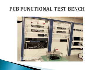
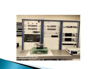
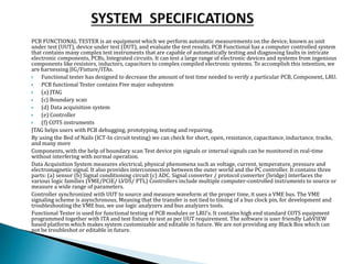
Printed circuit board (PCB) functional tester performs critical validation process performed on manufactured PCBs to verify the board’s functionality meets the original design requirements and specifications. Thorough functional testing helps ensure the reliability and performance of PCBs before deployment.
Testing coverage-
Validate continuity and isolation: Verify electrical connectivity and isolation between traces using in-circuit testing (ICT) and flying probe testing to check for opens and shorts.
Confirm impedance: Match measured impedance of traces and interconnects to design values to prevent signal degradation.
Verify power integrity: Check PCB operation under different power conditions to avoid errors from insufficient power delivery.
Assess signal integrity: Examine signal quality under high-speed conditions to prevent distortion and interference.
Test functionality: Stimulate the PCB with input signals and power to check outputs match expected responses based on design.
Confirm robustness: Subject PCB to temperature cycling, vibration, shock to validate resilience and durability.
Execute regression testing: Retest functionality after modifications to ensure no side effects.
Printed circuit board (PCB) FUNCATIONAL TEST BENCH.pptx
1.
2.
3. Printed circuit board (PCB) functional tester performs critical validation process performed
on manufactured PCBs to verify the board’s functionality meets the original design
requirements and specifications. Thorough functional testing helps ensure the reliability
and performance of PCBs before deployment.
Testing coverage-
Validate continuity and isolation: Verify electrical connectivity and isolation between
traces using in-circuit testing (ICT) and flying probe testing to check for opens and
shorts.
Confirm impedance: Match measured impedance of traces and interconnects to design
values to prevent signal degradation.
Verify power integrity: Check PCB operation under different power conditions to avoid
errors from insufficient power delivery.
Assess signal integrity: Examine signal quality under high-speed conditions to prevent
distortion and interference.
Test functionality: Stimulate the PCB with input signals and power to check outputs
match expected responses based on design.
Confirm robustness: Subject PCB to temperature cycling, vibration, shock to validate
resilience and durability.
Execute regression testing: Retest functionality after modifications to ensure no side
effects.
4.
5. Printed circuit board (PCB) functional tester performs critical validation process performed
on manufactured PCBs to verify the board’s functionality meets the original design
requirements and specifications. Thorough functional testing helps ensure the reliability
and performance of PCBs before deployment.
6.
7. PCB FUNCTIONAL TESTER is an equipment which we perform automatic measurements on the device, known as unit
under test (UUT), device under test (DUT), and evaluate the test results. PCB Functional has a computer controlled system
that contains many complex test instruments that are capable of automatically testing and diagnosing faults in intricate
electronic components, PCBs, Integrated circuits. It can test a large range of electronic devices and systems from ingenious
components like resistors, inductors, capacitors to complex compiled electronic systems. To accomplish this intention, we
are harnessing JIG/Fixture/ITAs.
Functional tester has designed to decrease the amount of test time needed to verify a particular PCB, Component, LRU.
PCB functional Tester contains Five major subsystem
(a) JTAG
(c) Boundary scan
(d) Data acquisition system
(e) Controller
(f) COTS instruments
JTAG helps users with PCB debugging, prototyping, testing and repairing.
By using the Bed of Nails (ICT-In circuit testing) we can check for short, open, resistance, capacitance, inductance, tracks,
and many more
Components, with the help of boundary scan Test device pin signals or internal signals can be monitored in real-time
without interfering with normal operation.
Data Acquisition System measures electrical, physical phenomena such as voltage, current, temperature, pressure and
electromagnetic signal. It also provides interconnection between the outer world and the PC controller. It contains three
parts: (a) sensor (b) Signal conditioning circuit (c) ADC. Signal converter / protocol converter (bridge) interfaces the
various logic families (VME/PCIE/ LVDS/ PTL) Controllers include multiple computer-controlled instruments to source or
measure a wide range of parameters.
Controller synchronized with UUT to source and measure waveform at the proper time, it uses a VME bus. The VME
signaling scheme is asynchronous, Meaning that the transfer is not tied to timing of a bus clock pin, for development and
troubleshooting the VME bus, we use logic analyzers and bus analyzers tools.
Functional Tester is used for functional testing of PCB modules or LRU’s. It contains high end standard COTS equipment
programmed together with ITA and test fixture to test as per UUT requirement. The software is user friendly LabVIEW
based platform which makes system customizable and editable in future. We are not providing any Black Box which can
not be troubleshot or editable in future.
8.
9. PCB Functional tester is capable of testing and validation of PCB design and working
characteristics of RF, Digital, Analog and Optical PCBs. Functional tester has the
capability and flexibility to provide the following minimum testing and diagnostic
capabilities
Functional working characteristics testing of PCB
Fault detection and report generation for quick resolution
Boundary Scan(J-tag) testing of IC on board
Functional Testing to simulate the actual working scenario of MODULE and LRU’s
Optical simulation and testing for optical boards and cables