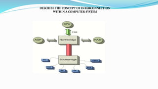
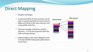
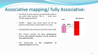
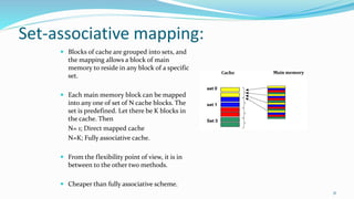
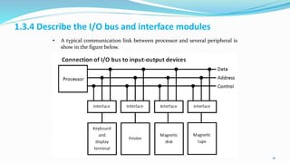
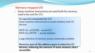
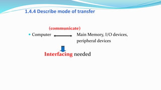
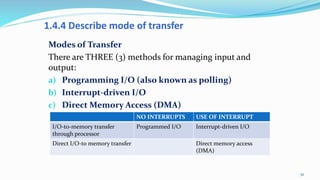
1
2
SUMMARY: This topic introduces computer architecture
and computer organisation, concepts of cache memory and
Input / Output in computer system
CLO1- Explain effectively computer function, input, output
and central processing unit in computer system. (C2, PLO1)
1. Define computer architecture and computer
organisation
2. Describe the concept of interconnection within a
computer system as follows:
Interconnection structures
Bus interconnection
3
Computer architecture Computer organization
• The science of integrating those components to
achieve a level of functionality and
performance.
• attributes in computer system as viewed by
programmer and have a direct impact to logic
execution of a program.
• The components from which computers
are built.
• component that linked with operational
unit of a computer system
Example :
• Instruction sets and formats, operation codes,
number of bit use, data type , data size,
techniques for addressing memory and types of
registers, main memory access methods and
input output mechanism.
Example :
• hardware technology, interface to
peripheral devices , clock frequency ,
memory technology , (memory type) ,
signalling method, control signal, size of
the physical memory, all physical aspects
of computer systems
• architecture may maintained for hundred years
such Von Neumann architecture.
• organisation may change as rapid changes
of technology
• one computer model, for example Intel x86;
may maintained its architecture but differ in its
organisation.
Computer top level structure
5
The major structural components of CPU:
1. Control unit: Controls all the operation of the CPU . The CU determines
the sequence in which computer programs and instruction are executed.
2. Arithmetic and logic unit (ALU): Performs the computer’s data
processing functions. Such as performs arithmetic/ logic computations,
Example of arithmetic operation is - +, -, x, / and perform Logical
Operation – AND, OR, NOT.
3. Registers: Provides internal storage to the CPU. It is fast internal storage
and used to temporarily store addresses, data, and processor status.
4. CPU interconnection/ internal bus: Some mechanism that provides for
communication among the control unit, ALU, and registers
Basic organization of computer system
Input: provide instruction or data to the system. In order for a
computer to receive the requests and instructions of the user, some
methods of inputting data and information to the computer are
required.
Output: Needs to display the result to the user and to communicate
with the user and display information that is being worked on,
output device is required
Storage: Used to store instruction or data. Operation on data
requires access for more than one time, so data and instruction have
to be stored temporarily
Control: Control the processing of instructions and the movement
of data from one part of the CPU to another.
ALU: Where arithmetic and Boolean logical calculations are
performed
DESCRIBE THE CONCEPT OF INTERCONNECTION
WITHIN A COMPUTER SYSTEM
Types of transfers:
 Memory to CPU: The CPU reads an
instruction or data from memory.
 CPU to memory: The CPU writes a
data to memory.
 I/O to CPU:The CPU reads data from
an I/O device via an I/O module.
 CPU to I/O: The CPU sends data to
the I/O device.
 I/O to or from memory: For these
two cases, an I/O module is allowed to
exchange data directly with memory,
without going through the CPU, using
direct memory access (DMA).
10
The interconnection
structure must support
the types of transfers.
BUS INTERCONNECTION
 Interconnection structure is the collection of paths connecting the various modules.
 A bus is a communication pathway connecting two or more devices.
 A sequence of bits can be transmit across a single line.
 Several lines can be used to transmit bits simultaneously (in parallel).
 A bus that connects major components (CPU,Memory,I/O) is called System Bus.
11
Data Lines / bus
 Provide a path for moving data between system modules.
 These lines, collectively, are called the data bus
 The data bus typically consists of 8, 16 or 32 separate lines, the numbers of
lines being transferred to as the width of the data bus.
 Each line carry only 1 bit at a time, the number of lines determines how
many bits can transferred at a time - overall system performance.
12
The Address Lines/ bus
 Used to designate the source or destination of the data on the data bus
 The width of the address bus determines the maximum possible memory
capacity of the system.
13
14
When data is saved to (or loaded from) memory, the address of the
store location at which it is to be stored (or loaded) must also be sent.
The address of data always travels along an address bus.
The Control Lines/ bus
 Used to control the access to and the use of the data and address lines.
 Typical control lines include:
 Memory write
 Memory read
 I/O write
 I/O read
 Clock
 Reset
15
The operation of the bus
 If one module wishes to send data:
 obtain the use of the bus
 transfer data via the bus
 If one module wishes to request data:
 obtain the use of the bus
 Transfer request to the other module over the control and address lines, then
wait for that second module to send the data.
16
 The following list are common expansion buses(
internal bus) in a PC system:
a) Industry Standard Architecture (ISA) – no longer used
b) Extended Industry Standard Architecture (EISA) – no
longer used
c) Peripheral Component Interconnect (PCI)
d) Accelerated Graphics Port (AGP)
e) Peripheral Component Interconnect Express (PCIe)
f) Mini-PCI
17
1. Define cache memory
2. Describe the types mapping of cache memory
3. Explain the cache initialization
18
Background: RAM on the
Motherboard
 Loses all data when PC is turned off (except data stored
on CMOS chip)
 Two categories
 Static RAM (SRAM)
 Fast
 Used as a memory cache
 Dynamic RAM (DRAM)
 Slower; requires constant refreshing
19
DRAM
20
SRAM
21
How Memory Caching Works
22
 Cache memory is a hardware cache used by CPU of computer to reduce
the average cost (time or energy) to access data from the main memory.
 When a program is running and the CPU needs to read data or
program instructions from RAM, the CPU checks first to see whether
the data is in cache memory or not.
 If the data is not there, the CPU reads the data from RAM into its
registers, but it also loads a copy of the data into cache memory.
 The next time the CPU needs that same data, it finds it in the cache
memory and saves the time needed to load the data from RAM.
24
25
26
27
1.2.2 Types of cache memory
The transformation of data from main memory
to cache memory is called mapping. There are
THREE (3) types of mapping procedures of practical
interest when considering the organization of cache
memory:
 Direct mapping
 Associative mapping
 Set-associative mapping
28
Direct Mapping
29
• Simplest technique.
• A particular block of main memory can be
map to a particular block of cache memory.
• Maps each block of the main memory into
one possible cache line
• The least complex of all three caching
schemes -- it is far less expensive than the
other caching schemes.
• Disadvantage is that Direct Mapped cache
is far less flexible making the performance
much lower.
Associative mapping/ fully Associative:
 Any block of main memory can potentially reside in
any cache block position. This is much more
flexible mapping method.
 Flexible – higher costs (must search all 128 tag
patterns to determine if a given block is in cache.
 Existing blocks only need to be ejected if cache is full.
 This scheme provides the best performance
because any memory location can be stored at
any cache location.
 The disadvantage is the complexity of
implementing this scheme.
30
Set-associative mapping:
 Blocks of cache are grouped into sets, and
the mapping allows a block of main
memory to reside in any block of a specific
set.
 Each main memory block can be mapped
into any one of set of N cache blocks. The
set is predefined. Let there be K blocks in
the cache. Then
N= 1; Direct mapped cache
N=K; Fully associative cache.
 From the flexibility point of view, it is in
between to the other two methods.
 Cheaper than fully associative scheme.
31
1.2.3 Cache initialization
 One more aspect of cache organization that must be taken
into consideration is the problem of initialization
 The cache is initialized when power is applied to the
computer or when the main memory is loaded with a
complete set of program from secondary memory.
 After initialization the cache is considered to be empty, but
in effect it contains non-valid data.
 It is customary to include with each word in cache a valid
bit to indicate whether or not the word contains valid data.
32
1.2.3 Cache initialization
 The cache is initialized by clearing all the valid bits to
0.
 The valid bit of a particular cache word is set to 1 the
first time this word is loaded from the main memory
and stays set unless the cache has to be initialized.
 If the valid bit happens to be 0, the new word
automatically replaces the invalid data.
 Thus, the initialization condition has the effect of
forcing misses from the cache until it fills with valid
data.
33
1. Define I/O
2. Draw the I/O module
3. List I/O devices
4. Describe the I/O bus and interface module
34
1.3.1 Define I/O module????
 I/O MODULE
 The input/output subsystem of a computer that, provides an efficient mode
of communication between the central system and the outside environment.
35
1.3.2 I/O MODULE BLOCK DIAGRAM
36
 This module connect to the rest of
the computer via a set of signal line.
 Data transferred to and from the
module are buffered in one or more
data registers.
 There may be also be one or more
status register that provide current
status information.
 A status register also function as
control register (to accept detailed
control information from the
processor).
 The logic interact with processor via
a set of control lines. The processor
uses the control line to issue
commands to the I/O module.
37
1.3.2 I/O MODULE DIAGRAM
1) Control and Timing. – the i/o module must be able to co-
ordinate the flow of data between the internal recourses (
such as processor, memory) and external devices
2) CPU Communicating.- involve in following task:
 exchange of data between processor and i/o module.
 Command decoding- i/o module accepts command sent from
processor
 Status reporting- the devices must able to report its status to
processor
 Address recognition- each i/o devices has unique address and i/o
module must recognize this address
38
 3) Device Communication. – the i/o module must be
able to perform device communication such as
reporting
 4) Data Buffering. – this is needed as there is a speed
mismatch between speed of data transfer between
processor and memory and external devices.
 5) Error Detection. – the i/o module must be able to
detect error and report them to the processor. These
error may be mechanical error ( such as paper jam in a
printer) or changes in the bits pattern of transmitted
data.
39
1.3.3 List the I/O devices
40
1.3.4 Describe the I/O bus and interface modules
41
• A typical communication link between processor and several peripheral is
show in the figure below.
1. Define the asynchronous serial transfer
2. Describe the asynchronous communication interface
3. Differentiate the characteristic between isolated and memory mapped
I/O
4. Describe mode of transfer:
 Programmed I/O
 Interrupt-initiated I/O
 Direct memory Access
42
43
Characteristic Asynchronous Synchronous
Transmission
technique
Use serial
communication
Use serial
communication
Comparatives
capacity
Data transmit one
character at one
time
Data transmit block
(bunch of character)
at one time
Distance
Limitation
long shorter
Sync method Start and stop bit Clock speed
Comparatives
capacity
Low speed due to
serial transmission
More efficient due to
parallel transmission
Costing Simple and cheap Much cost due to
mechanism
Comparison between Asynchronous & Synchronous Communication
Asynchronous Serial Transfer
44
Asynchronous Serial Transfer
 The term asynchronous is usually used to describe communications in
which data can be transmitted intermittently rather than in a steady
stream.
 For example, a telephone conversation is asynchronous because both
parties can talk whenever they like. If the communication were
synchronous, each party would be required to wait a specified interval
before speaking.
 The difficulty with asynchronous communications is that the receiver
must have a way to distinguish between valid data and noise.
45
1.4.2 The asynchronous communication interface
The asynchronous communication interface
A serial asynchronous data transmission technique used in many
interactive terminals employs special bits that are inserted in both ends
of the character code. With this technique, each character consist of
three parts:
 Start bit—indicates the beginning of the data word
 Stop bit—indicates the end of the data word
 Character bit / Data bits—the actual data to be transmitted
 Parity bit- to detect error in data transmission
46
1.4.3 Differentiate the characteristic between
Isolated and memory mapped I/O
47
Isolated I/O Memory Mapped I/O
Isolated I/O uses separate memory
space.
Memory mapped I/O uses
memory from the main memory.
Limited instructions can be used.
Those are IN, OUT, INS, OUTS.
Any instruction which references
to memory can be used.
The addresses for Isolated I/O
devices are called ports.
Memory mapped I/O devices are
treated as memory locations on
the memory map.
1.4.3 Differentiate the characteristic between Isolated and
memory mapped I/O
 Memory-mapped I/O: A method of addressing I/O modules and
external devices.
1. A single address space
is used for both main memory
and I/O addresses
48
Memory-mapped I/O
2. Same machine instructions are used both for memory
read/write and for I/O.
49
No special commands for I/O
Same machine instructions to access memory and I/O
devices
MOV AL, 0COOOh – access I/O
MOV AL,0FFFFh -- access memory
Large selection of memory access commands available
However, part of the address space is taken by I/O
devices, reducing the amount of main memory that’s
accessible.
1.4.3 Differentiate the characteristic between
Isolated and memory mapped I/O
50
Isolated I/O Memory Mapped I/O
Isolated I/O uses separate memory
space.
Memory mapped I/O uses
memory from the main memory.
Limited instructions can be used.
Those are IN, OUT, INS, OUTS.
Any instruction which references
to memory can be used.
The addresses for Isolated I/O
devices are called ports.
Memory mapped I/O devices are
treated as memory locations on
the memory map.
1.4.4 Describe mode of transfer
(communicate)
 Computer Main Memory, I/O devices,
peripheral devices
Interfacing needed
1.4.4 Describe mode of transfer
Modes of Transfer
There are THREE (3) methods for managing input and
output:
a) Programming I/O (also known as polling)
b) Interrupt-driven I/O
c) Direct Memory Access (DMA)
52
NO INTERRUPTS USE OF INTERRUPT
I/O-to-memory transfer
through processor
Programmed I/O Interrupt-driven I/O
Direct I/O-to memory transfer Direct memory access
(DMA)
 A computer receives input from a number of different sources. Characters
keyed in on the keyboard, the click of a mouse, data from scanner , data
from printer. The arrival of this type of input is not necessary expected at
any particular time and the computer has to have a way of detecting it.
 There are two ways that this can happen, Programming I/O (polling )
and interrupts.
 Both of these method allow the processor to deal with events that can
happen at any time and that are not related to the process it is currently
running.
Programming I/O (also known as
polling)
 Programmed I/O (PIO) refers to data transfers initiated by a CPU under
driver software control to access registers or memory on a device.
 Polling is the process where the microprocessor waits for an external
device to check for its readiness.
 The microprocessor does not do anything else then checking the status of
the device.
 Polling is often used with low level hardware.
Polling has disadvantage that:
1. if there are too many devices to check, the time required to poll
them can exceed the time available to service the I/O device.
2. the processor has to wait a long time for the I/O module of concern
to be ready for either reception or transmission of data.
3. The processor, while waiting, must repeatedly interrogate the
status of the I/O module. As a result, the level of the performance
of the entire system is severely degraded.
1. CPU checks status of device by looking at status register in I/O module. (
polling)
2. If status register of device 1 is ready (set to 0)- data will be put into bus data
and send to CPU to deal it.
3. If status register of device 1 is busy ( set to 1) – CPU will polling other devices to
check the status of devices.
4. If data is ready in data register , it can be effective data transfer because data
can be input / output depending on what is particular task to execute.
56
Interrupt –DRIVEN I/O
 Interrupt is a signal to microprocessor
from a device that requires attention.
The microprocessor will respond by setting
aside execution of its current task and deal
with the interrupting device.
 When the interrupting device has been
dealt with, the microprocessor continuous
with its original task as if had never been
interrupted
58
1. With interrupt-driven I/O,
the CPU does not access a
device until it needs
servicing, and so it does
not get caught up in busy-
waits.
2. In interrupt-driven I/O,
the device requests service
through a special interrupt
request line that goes
directly to the CPU.
The Interrupt-Driven I/O
 The interrupt advantage:
 To ensure the I/O devices or peripheral devices interrupting
microprocessor to initiate.
 Reduce time and cost in such a way that interrupt only occurs when
microprocessor receive an interrupt signal.
59
 Interrupt I/O is more efficient than programmed I/O because it
eliminates needless waiting.
 However, interrupt I/O still consumes a lot of processor time, because
every word of data that goes from memory to I/O module or from I/O
module to memory must pass through the processor
60
Priority Interrupt
1. Priority Interrupt is a system that determine which condition is to be
services first when two or more request arrive simultaneously.
2. Highest priority interrupt are served first.
3. Device with high speed transfer are given high priority and slow devices
such keyboards receive low priority.
4. When 2 devices interrupt the CPU at the same time the CPU will service
the device with highest priority first.
61
Direct Memory Access (DMA)
A direct memory access (DMA) device can
transfer data directly to and from memory
rather than using the CPU as an intermediary,
and can thus relieve congestion on the system
bus.
In this mode, the I/O module and main
memory exchange data directly, without
processor involvement.
62
Direct Memory Access (DMA)
 In DMA,
Data transfer between memory peripheral
Controlled externally
Microprocessor not involved during transfer
This method used in cases where microprocessor
control too slow
DMA process requires a controlled chip – 8257
DMA controller
Direct Memory Access (DMA)
DMA Controller
 DMA services are usually provided by DMA
controller, which is, itself a specialized
processor whose specialty is transferring data
directly to or from I/O devices and memory.
 It takes the place of microprocessor. The
transfer directly between memory and
peripherals I/O
64
Direct Memory Access (DMA)
65
Diagram Modul DMA
66
 The DMA module is capable of representing the
processor and taking over control of the system from
the processor. It needs to do this to transfer data to and
from memory over the system bus.
 For this purpose, the DMA module must use the bus
only when the processor does not need it, or it must
force the processor to suspend operation temporarily.
 The second technique is more common and is referred
to as cycle stealing, because the DMA module in
effect steals a bus cycle.
67
 When the processor wishes to read or write a block of data, it issues a
command to the DMA module, by sending to the DMA module the
following information:
1. Whether a read or write is requested, using the read or
write control line between the processor and the DMA
module
2. The address of the I/O device involved, communicated
on the data lines
3. The starting location in memory to read from or write to,
communicated on the data lines and stored by the DMA
module in its address register
68
CPU DMA module
1, 2,3,4
4. The number of words to be read or written, again
communicated via the data lines and stored in the data count
register.
The processor then continues with other work. It has given this
I/O operation to the DMA module. The DMA module transfers
the entire block of data, one word at a time, directly to or from
memory, without going through the processor.
69
CPU DMA module memory
When the transfer is complete, the DMA module sends an interrupt signal to
the processor. Thus, the processor is involved only at the beginning and
end of the transfer.
1, 2,3,4
Send interrupt signal,
after complete.
 Data transfer using this method is more faster
than normal method.
 The CPU would first tell the DMA controller what it
should do, and then the CPU can continue executing
other processes while the DMA controller uses the bus
 During data transfer from peripheral , DMA controller
will control bus system.
 External peripheral, will use interrupt technique to tell
DMA controller if there are a data to be transfer or not.

Computer System Architecture

  • 1.
  • 2.
    2 SUMMARY: This topicintroduces computer architecture and computer organisation, concepts of cache memory and Input / Output in computer system CLO1- Explain effectively computer function, input, output and central processing unit in computer system. (C2, PLO1)
  • 3.
    1. Define computerarchitecture and computer organisation 2. Describe the concept of interconnection within a computer system as follows: Interconnection structures Bus interconnection 3
  • 4.
    Computer architecture Computerorganization • The science of integrating those components to achieve a level of functionality and performance. • attributes in computer system as viewed by programmer and have a direct impact to logic execution of a program. • The components from which computers are built. • component that linked with operational unit of a computer system Example : • Instruction sets and formats, operation codes, number of bit use, data type , data size, techniques for addressing memory and types of registers, main memory access methods and input output mechanism. Example : • hardware technology, interface to peripheral devices , clock frequency , memory technology , (memory type) , signalling method, control signal, size of the physical memory, all physical aspects of computer systems • architecture may maintained for hundred years such Von Neumann architecture. • organisation may change as rapid changes of technology • one computer model, for example Intel x86; may maintained its architecture but differ in its organisation.
  • 5.
    Computer top levelstructure 5
  • 6.
    The major structuralcomponents of CPU: 1. Control unit: Controls all the operation of the CPU . The CU determines the sequence in which computer programs and instruction are executed. 2. Arithmetic and logic unit (ALU): Performs the computer’s data processing functions. Such as performs arithmetic/ logic computations, Example of arithmetic operation is - +, -, x, / and perform Logical Operation – AND, OR, NOT. 3. Registers: Provides internal storage to the CPU. It is fast internal storage and used to temporarily store addresses, data, and processor status. 4. CPU interconnection/ internal bus: Some mechanism that provides for communication among the control unit, ALU, and registers
  • 7.
    Basic organization ofcomputer system
  • 8.
    Input: provide instructionor data to the system. In order for a computer to receive the requests and instructions of the user, some methods of inputting data and information to the computer are required. Output: Needs to display the result to the user and to communicate with the user and display information that is being worked on, output device is required Storage: Used to store instruction or data. Operation on data requires access for more than one time, so data and instruction have to be stored temporarily Control: Control the processing of instructions and the movement of data from one part of the CPU to another. ALU: Where arithmetic and Boolean logical calculations are performed
  • 9.
    DESCRIBE THE CONCEPTOF INTERCONNECTION WITHIN A COMPUTER SYSTEM
  • 10.
    Types of transfers: Memory to CPU: The CPU reads an instruction or data from memory.  CPU to memory: The CPU writes a data to memory.  I/O to CPU:The CPU reads data from an I/O device via an I/O module.  CPU to I/O: The CPU sends data to the I/O device.  I/O to or from memory: For these two cases, an I/O module is allowed to exchange data directly with memory, without going through the CPU, using direct memory access (DMA). 10 The interconnection structure must support the types of transfers.
  • 11.
    BUS INTERCONNECTION  Interconnectionstructure is the collection of paths connecting the various modules.  A bus is a communication pathway connecting two or more devices.  A sequence of bits can be transmit across a single line.  Several lines can be used to transmit bits simultaneously (in parallel).  A bus that connects major components (CPU,Memory,I/O) is called System Bus. 11
  • 12.
    Data Lines /bus  Provide a path for moving data between system modules.  These lines, collectively, are called the data bus  The data bus typically consists of 8, 16 or 32 separate lines, the numbers of lines being transferred to as the width of the data bus.  Each line carry only 1 bit at a time, the number of lines determines how many bits can transferred at a time - overall system performance. 12
  • 13.
    The Address Lines/bus  Used to designate the source or destination of the data on the data bus  The width of the address bus determines the maximum possible memory capacity of the system. 13
  • 14.
    14 When data issaved to (or loaded from) memory, the address of the store location at which it is to be stored (or loaded) must also be sent. The address of data always travels along an address bus.
  • 15.
    The Control Lines/bus  Used to control the access to and the use of the data and address lines.  Typical control lines include:  Memory write  Memory read  I/O write  I/O read  Clock  Reset 15
  • 16.
    The operation ofthe bus  If one module wishes to send data:  obtain the use of the bus  transfer data via the bus  If one module wishes to request data:  obtain the use of the bus  Transfer request to the other module over the control and address lines, then wait for that second module to send the data. 16
  • 17.
     The followinglist are common expansion buses( internal bus) in a PC system: a) Industry Standard Architecture (ISA) – no longer used b) Extended Industry Standard Architecture (EISA) – no longer used c) Peripheral Component Interconnect (PCI) d) Accelerated Graphics Port (AGP) e) Peripheral Component Interconnect Express (PCIe) f) Mini-PCI 17
  • 18.
    1. Define cachememory 2. Describe the types mapping of cache memory 3. Explain the cache initialization 18
  • 19.
    Background: RAM onthe Motherboard  Loses all data when PC is turned off (except data stored on CMOS chip)  Two categories  Static RAM (SRAM)  Fast  Used as a memory cache  Dynamic RAM (DRAM)  Slower; requires constant refreshing 19
  • 20.
  • 21.
  • 22.
  • 23.
     Cache memoryis a hardware cache used by CPU of computer to reduce the average cost (time or energy) to access data from the main memory.  When a program is running and the CPU needs to read data or program instructions from RAM, the CPU checks first to see whether the data is in cache memory or not.  If the data is not there, the CPU reads the data from RAM into its registers, but it also loads a copy of the data into cache memory.  The next time the CPU needs that same data, it finds it in the cache memory and saves the time needed to load the data from RAM.
  • 24.
  • 25.
  • 26.
  • 27.
  • 28.
    1.2.2 Types ofcache memory The transformation of data from main memory to cache memory is called mapping. There are THREE (3) types of mapping procedures of practical interest when considering the organization of cache memory:  Direct mapping  Associative mapping  Set-associative mapping 28
  • 29.
    Direct Mapping 29 • Simplesttechnique. • A particular block of main memory can be map to a particular block of cache memory. • Maps each block of the main memory into one possible cache line • The least complex of all three caching schemes -- it is far less expensive than the other caching schemes. • Disadvantage is that Direct Mapped cache is far less flexible making the performance much lower.
  • 30.
    Associative mapping/ fullyAssociative:  Any block of main memory can potentially reside in any cache block position. This is much more flexible mapping method.  Flexible – higher costs (must search all 128 tag patterns to determine if a given block is in cache.  Existing blocks only need to be ejected if cache is full.  This scheme provides the best performance because any memory location can be stored at any cache location.  The disadvantage is the complexity of implementing this scheme. 30
  • 31.
    Set-associative mapping:  Blocksof cache are grouped into sets, and the mapping allows a block of main memory to reside in any block of a specific set.  Each main memory block can be mapped into any one of set of N cache blocks. The set is predefined. Let there be K blocks in the cache. Then N= 1; Direct mapped cache N=K; Fully associative cache.  From the flexibility point of view, it is in between to the other two methods.  Cheaper than fully associative scheme. 31
  • 32.
    1.2.3 Cache initialization One more aspect of cache organization that must be taken into consideration is the problem of initialization  The cache is initialized when power is applied to the computer or when the main memory is loaded with a complete set of program from secondary memory.  After initialization the cache is considered to be empty, but in effect it contains non-valid data.  It is customary to include with each word in cache a valid bit to indicate whether or not the word contains valid data. 32
  • 33.
    1.2.3 Cache initialization The cache is initialized by clearing all the valid bits to 0.  The valid bit of a particular cache word is set to 1 the first time this word is loaded from the main memory and stays set unless the cache has to be initialized.  If the valid bit happens to be 0, the new word automatically replaces the invalid data.  Thus, the initialization condition has the effect of forcing misses from the cache until it fills with valid data. 33
  • 34.
    1. Define I/O 2.Draw the I/O module 3. List I/O devices 4. Describe the I/O bus and interface module 34
  • 35.
    1.3.1 Define I/Omodule????  I/O MODULE  The input/output subsystem of a computer that, provides an efficient mode of communication between the central system and the outside environment. 35
  • 36.
    1.3.2 I/O MODULEBLOCK DIAGRAM 36
  • 37.
     This moduleconnect to the rest of the computer via a set of signal line.  Data transferred to and from the module are buffered in one or more data registers.  There may be also be one or more status register that provide current status information.  A status register also function as control register (to accept detailed control information from the processor).  The logic interact with processor via a set of control lines. The processor uses the control line to issue commands to the I/O module. 37
  • 38.
    1.3.2 I/O MODULEDIAGRAM 1) Control and Timing. – the i/o module must be able to co- ordinate the flow of data between the internal recourses ( such as processor, memory) and external devices 2) CPU Communicating.- involve in following task:  exchange of data between processor and i/o module.  Command decoding- i/o module accepts command sent from processor  Status reporting- the devices must able to report its status to processor  Address recognition- each i/o devices has unique address and i/o module must recognize this address 38
  • 39.
     3) DeviceCommunication. – the i/o module must be able to perform device communication such as reporting  4) Data Buffering. – this is needed as there is a speed mismatch between speed of data transfer between processor and memory and external devices.  5) Error Detection. – the i/o module must be able to detect error and report them to the processor. These error may be mechanical error ( such as paper jam in a printer) or changes in the bits pattern of transmitted data. 39
  • 40.
    1.3.3 List theI/O devices 40
  • 41.
    1.3.4 Describe theI/O bus and interface modules 41 • A typical communication link between processor and several peripheral is show in the figure below.
  • 42.
    1. Define theasynchronous serial transfer 2. Describe the asynchronous communication interface 3. Differentiate the characteristic between isolated and memory mapped I/O 4. Describe mode of transfer:  Programmed I/O  Interrupt-initiated I/O  Direct memory Access 42
  • 43.
    43 Characteristic Asynchronous Synchronous Transmission technique Useserial communication Use serial communication Comparatives capacity Data transmit one character at one time Data transmit block (bunch of character) at one time Distance Limitation long shorter Sync method Start and stop bit Clock speed Comparatives capacity Low speed due to serial transmission More efficient due to parallel transmission Costing Simple and cheap Much cost due to mechanism Comparison between Asynchronous & Synchronous Communication
  • 44.
  • 45.
    Asynchronous Serial Transfer The term asynchronous is usually used to describe communications in which data can be transmitted intermittently rather than in a steady stream.  For example, a telephone conversation is asynchronous because both parties can talk whenever they like. If the communication were synchronous, each party would be required to wait a specified interval before speaking.  The difficulty with asynchronous communications is that the receiver must have a way to distinguish between valid data and noise. 45
  • 46.
    1.4.2 The asynchronouscommunication interface The asynchronous communication interface A serial asynchronous data transmission technique used in many interactive terminals employs special bits that are inserted in both ends of the character code. With this technique, each character consist of three parts:  Start bit—indicates the beginning of the data word  Stop bit—indicates the end of the data word  Character bit / Data bits—the actual data to be transmitted  Parity bit- to detect error in data transmission 46
  • 47.
    1.4.3 Differentiate thecharacteristic between Isolated and memory mapped I/O 47 Isolated I/O Memory Mapped I/O Isolated I/O uses separate memory space. Memory mapped I/O uses memory from the main memory. Limited instructions can be used. Those are IN, OUT, INS, OUTS. Any instruction which references to memory can be used. The addresses for Isolated I/O devices are called ports. Memory mapped I/O devices are treated as memory locations on the memory map.
  • 48.
    1.4.3 Differentiate thecharacteristic between Isolated and memory mapped I/O  Memory-mapped I/O: A method of addressing I/O modules and external devices. 1. A single address space is used for both main memory and I/O addresses 48
  • 49.
    Memory-mapped I/O 2. Samemachine instructions are used both for memory read/write and for I/O. 49 No special commands for I/O Same machine instructions to access memory and I/O devices MOV AL, 0COOOh – access I/O MOV AL,0FFFFh -- access memory Large selection of memory access commands available However, part of the address space is taken by I/O devices, reducing the amount of main memory that’s accessible.
  • 50.
    1.4.3 Differentiate thecharacteristic between Isolated and memory mapped I/O 50 Isolated I/O Memory Mapped I/O Isolated I/O uses separate memory space. Memory mapped I/O uses memory from the main memory. Limited instructions can be used. Those are IN, OUT, INS, OUTS. Any instruction which references to memory can be used. The addresses for Isolated I/O devices are called ports. Memory mapped I/O devices are treated as memory locations on the memory map.
  • 51.
    1.4.4 Describe modeof transfer (communicate)  Computer Main Memory, I/O devices, peripheral devices Interfacing needed
  • 52.
    1.4.4 Describe modeof transfer Modes of Transfer There are THREE (3) methods for managing input and output: a) Programming I/O (also known as polling) b) Interrupt-driven I/O c) Direct Memory Access (DMA) 52 NO INTERRUPTS USE OF INTERRUPT I/O-to-memory transfer through processor Programmed I/O Interrupt-driven I/O Direct I/O-to memory transfer Direct memory access (DMA)
  • 53.
     A computerreceives input from a number of different sources. Characters keyed in on the keyboard, the click of a mouse, data from scanner , data from printer. The arrival of this type of input is not necessary expected at any particular time and the computer has to have a way of detecting it.  There are two ways that this can happen, Programming I/O (polling ) and interrupts.  Both of these method allow the processor to deal with events that can happen at any time and that are not related to the process it is currently running.
  • 54.
    Programming I/O (alsoknown as polling)  Programmed I/O (PIO) refers to data transfers initiated by a CPU under driver software control to access registers or memory on a device.  Polling is the process where the microprocessor waits for an external device to check for its readiness.  The microprocessor does not do anything else then checking the status of the device.  Polling is often used with low level hardware.
  • 55.
    Polling has disadvantagethat: 1. if there are too many devices to check, the time required to poll them can exceed the time available to service the I/O device. 2. the processor has to wait a long time for the I/O module of concern to be ready for either reception or transmission of data. 3. The processor, while waiting, must repeatedly interrogate the status of the I/O module. As a result, the level of the performance of the entire system is severely degraded.
  • 56.
    1. CPU checksstatus of device by looking at status register in I/O module. ( polling) 2. If status register of device 1 is ready (set to 0)- data will be put into bus data and send to CPU to deal it. 3. If status register of device 1 is busy ( set to 1) – CPU will polling other devices to check the status of devices. 4. If data is ready in data register , it can be effective data transfer because data can be input / output depending on what is particular task to execute. 56
  • 57.
    Interrupt –DRIVEN I/O Interrupt is a signal to microprocessor from a device that requires attention. The microprocessor will respond by setting aside execution of its current task and deal with the interrupting device.  When the interrupting device has been dealt with, the microprocessor continuous with its original task as if had never been interrupted
  • 58.
    58 1. With interrupt-drivenI/O, the CPU does not access a device until it needs servicing, and so it does not get caught up in busy- waits. 2. In interrupt-driven I/O, the device requests service through a special interrupt request line that goes directly to the CPU. The Interrupt-Driven I/O
  • 59.
     The interruptadvantage:  To ensure the I/O devices or peripheral devices interrupting microprocessor to initiate.  Reduce time and cost in such a way that interrupt only occurs when microprocessor receive an interrupt signal. 59
  • 60.
     Interrupt I/Ois more efficient than programmed I/O because it eliminates needless waiting.  However, interrupt I/O still consumes a lot of processor time, because every word of data that goes from memory to I/O module or from I/O module to memory must pass through the processor 60
  • 61.
    Priority Interrupt 1. PriorityInterrupt is a system that determine which condition is to be services first when two or more request arrive simultaneously. 2. Highest priority interrupt are served first. 3. Device with high speed transfer are given high priority and slow devices such keyboards receive low priority. 4. When 2 devices interrupt the CPU at the same time the CPU will service the device with highest priority first. 61
  • 62.
    Direct Memory Access(DMA) A direct memory access (DMA) device can transfer data directly to and from memory rather than using the CPU as an intermediary, and can thus relieve congestion on the system bus. In this mode, the I/O module and main memory exchange data directly, without processor involvement. 62
  • 63.
    Direct Memory Access(DMA)  In DMA, Data transfer between memory peripheral Controlled externally Microprocessor not involved during transfer This method used in cases where microprocessor control too slow DMA process requires a controlled chip – 8257 DMA controller
  • 64.
    Direct Memory Access(DMA) DMA Controller  DMA services are usually provided by DMA controller, which is, itself a specialized processor whose specialty is transferring data directly to or from I/O devices and memory.  It takes the place of microprocessor. The transfer directly between memory and peripherals I/O 64
  • 65.
  • 66.
  • 67.
     The DMAmodule is capable of representing the processor and taking over control of the system from the processor. It needs to do this to transfer data to and from memory over the system bus.  For this purpose, the DMA module must use the bus only when the processor does not need it, or it must force the processor to suspend operation temporarily.  The second technique is more common and is referred to as cycle stealing, because the DMA module in effect steals a bus cycle. 67
  • 68.
     When theprocessor wishes to read or write a block of data, it issues a command to the DMA module, by sending to the DMA module the following information: 1. Whether a read or write is requested, using the read or write control line between the processor and the DMA module 2. The address of the I/O device involved, communicated on the data lines 3. The starting location in memory to read from or write to, communicated on the data lines and stored by the DMA module in its address register 68 CPU DMA module 1, 2,3,4
  • 69.
    4. The numberof words to be read or written, again communicated via the data lines and stored in the data count register. The processor then continues with other work. It has given this I/O operation to the DMA module. The DMA module transfers the entire block of data, one word at a time, directly to or from memory, without going through the processor. 69 CPU DMA module memory When the transfer is complete, the DMA module sends an interrupt signal to the processor. Thus, the processor is involved only at the beginning and end of the transfer. 1, 2,3,4 Send interrupt signal, after complete.
  • 70.
     Data transferusing this method is more faster than normal method.  The CPU would first tell the DMA controller what it should do, and then the CPU can continue executing other processes while the DMA controller uses the bus  During data transfer from peripheral , DMA controller will control bus system.  External peripheral, will use interrupt technique to tell DMA controller if there are a data to be transfer or not.