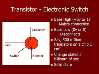
1) Transistors act as electronic switches that can be in either an "on" or "off" state, allowing circuits to perform logical operations.
2) Moore's Law predicts that the number of transistors on an integrated circuit will double about every two years.
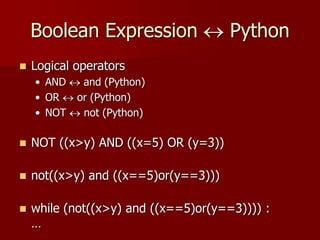
3) Logic gates such as AND, OR, and NOT gates are electronic devices that take binary inputs and produce binary outputs according to their specific logical functions.