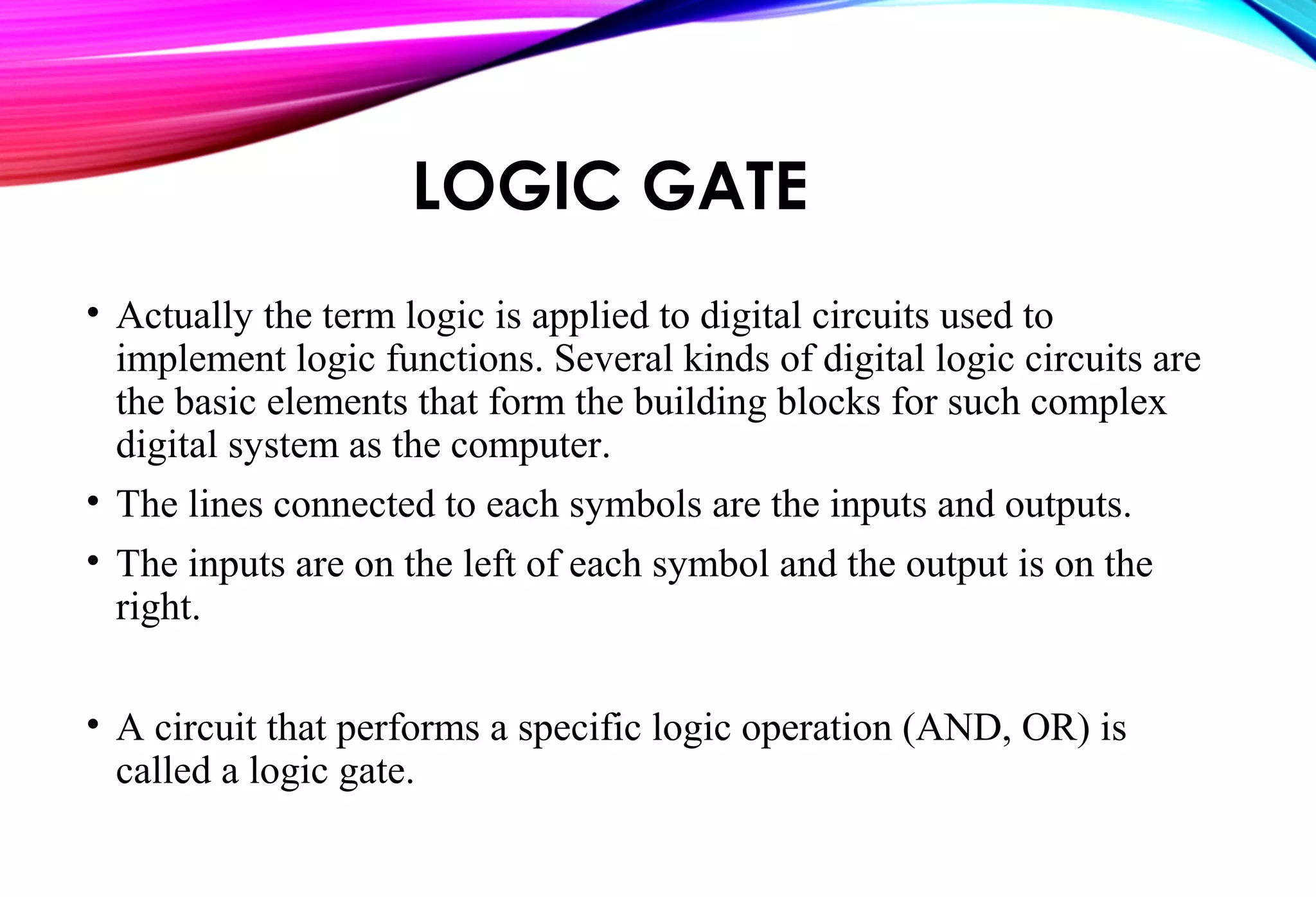
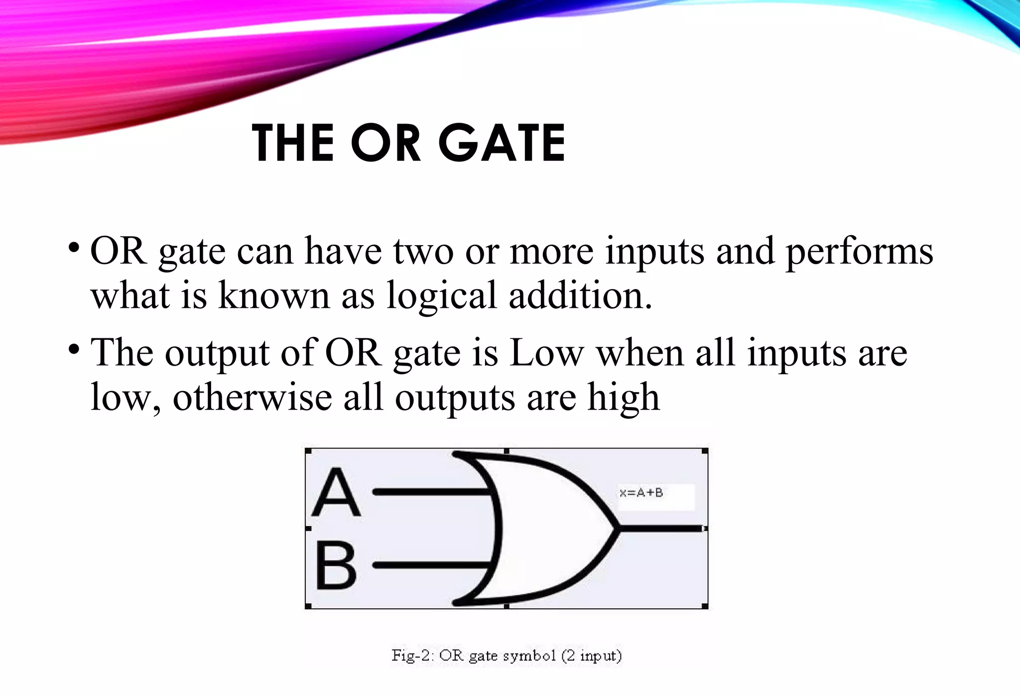
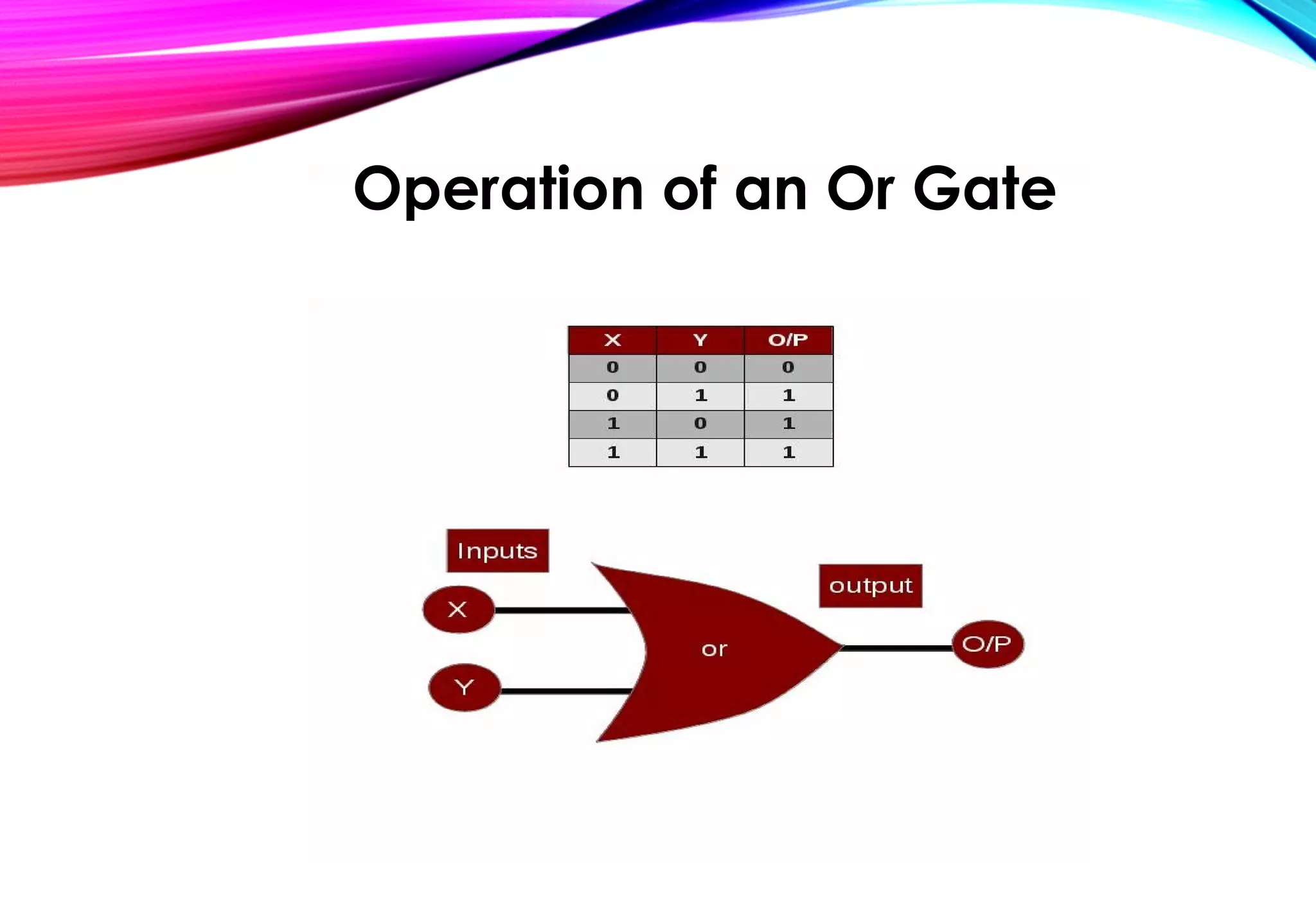
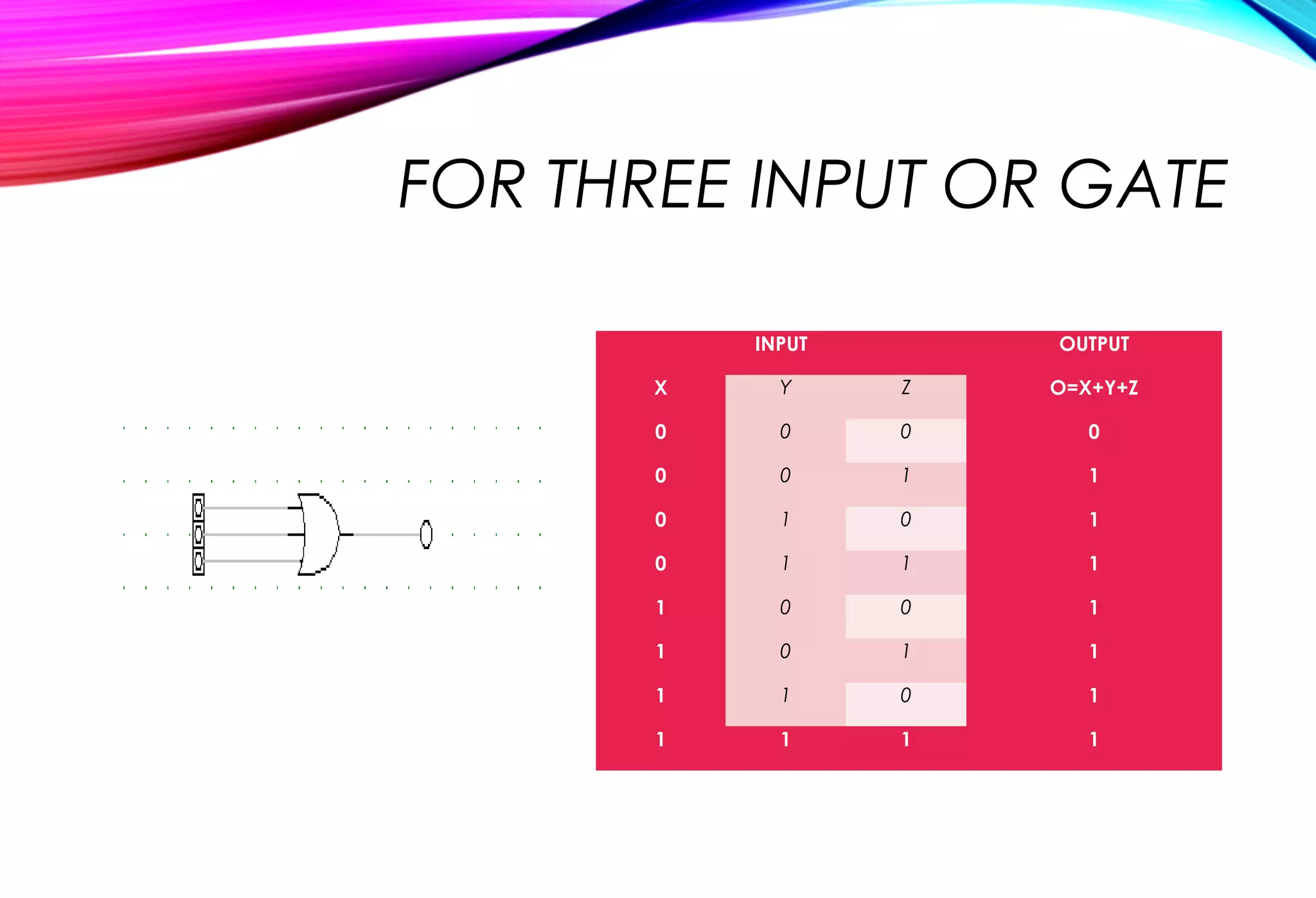
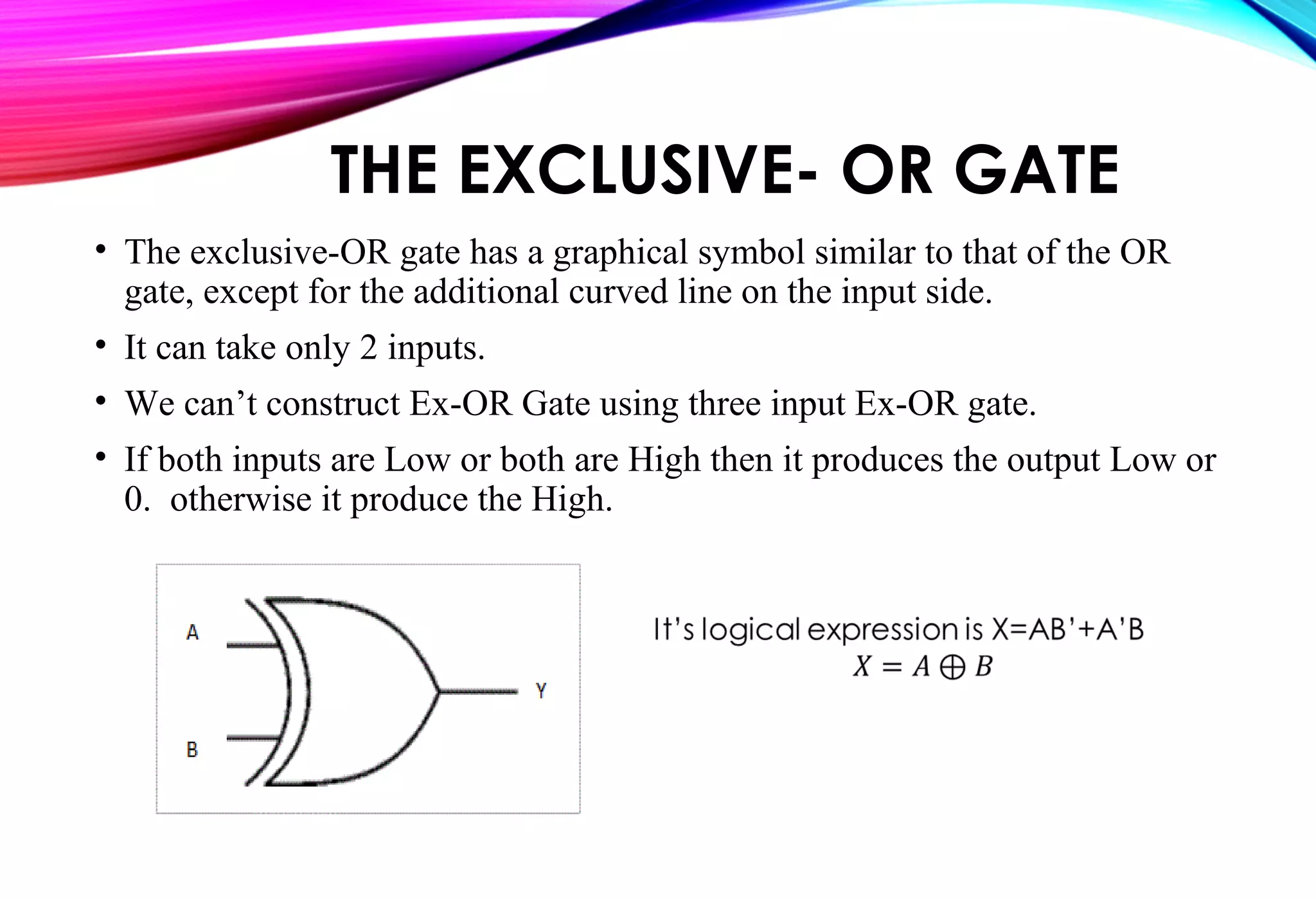
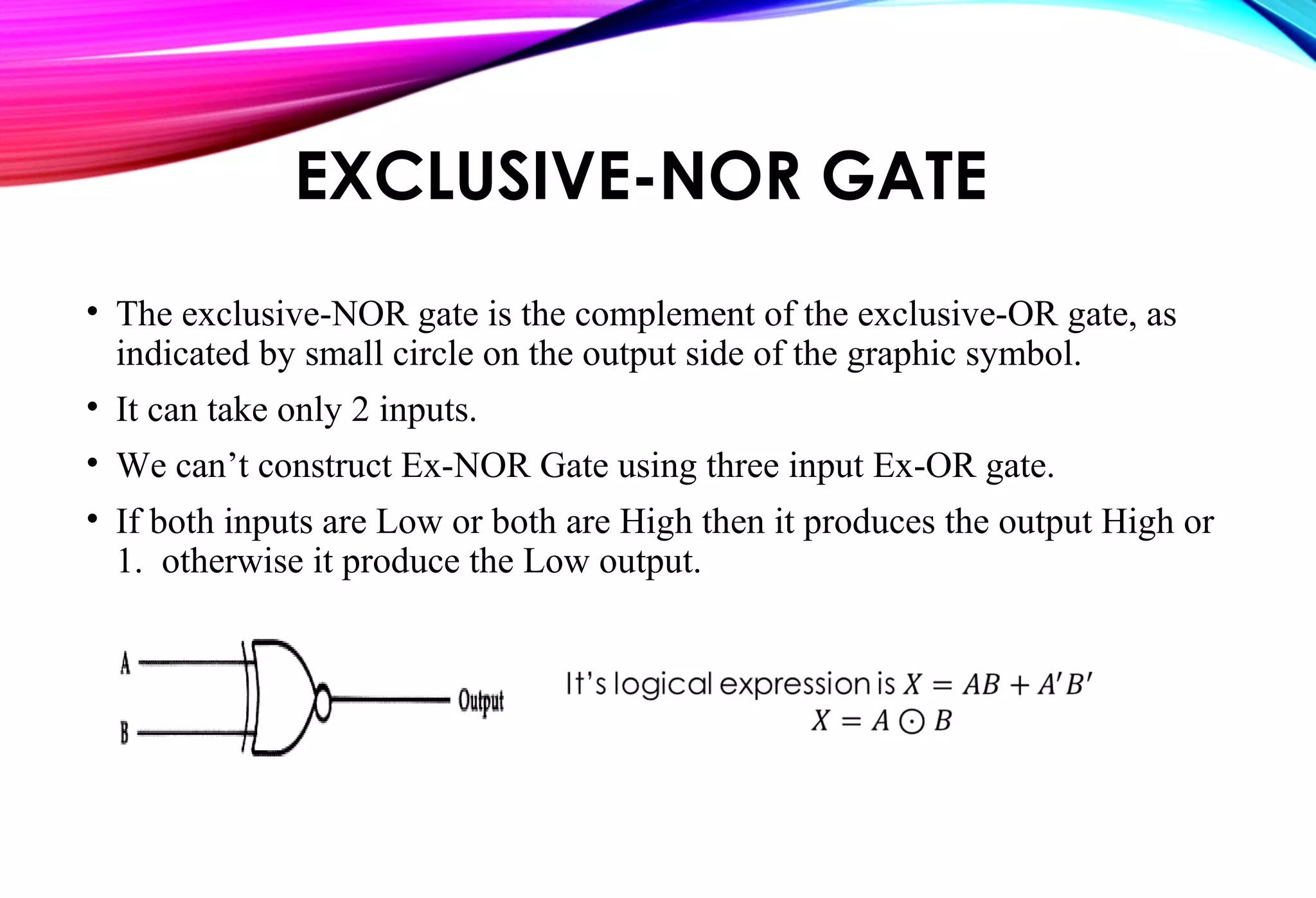
PRESENTED BY:
1. Abu Bakar Siddik ID: 141-19-1536
2. Al-Amin Prince ID: 141-19-1539
3. Samia Nur Tisha ID: 141-19-1535
4. Mst. Tamanna Yeasmin ID: 141-19-1548
Department of ETE
PRESENTEDPRESENTED TOTO::
Tasnuva Ali,Tasnuva Ali,
Senior LecturerSenior Lecturer
Department of ETEDepartment of ETE
Daffodil International UniversityDaffodil International University
LOGIC GATE
• Actually the term logic is applied to digital circuits used to
implement logic functions. Several kinds of digital logic circuits are
the basic elements that form the building blocks for such complex
digital system as the computer.
• The lines connected to each symbols are the inputs and outputs.
• The inputs are on the left of each symbol and the output is on the
right.
• A circuit that performs a specific logic operation (AND, OR) is
called a logic gate.
THE AND GATE
• An And gate is a basic logic gate whose output goes high
only when all its inputs are high and in no other condition.
An And gate is represented using the symbol:
OPERATION OF AND GATE
FOR THREE INPUT AND GATE
INPUT OUTPUT
X Y Z O=X.Y.Z
0 0 0 0
0 0 1 0
0 1 0 0
0 1 1 0
1 0 0 0
1 0 1 0
1 1 0 0
1 1 1 1
THE OR GATE
• OR gate can have two or more inputs and performs
what is known as logical addition.
• The output of OR gate is Low when all inputs are
low, otherwise all outputs are high
Operation of an Or Gate
FOR THREE INPUT OR GATE
INPUT OUTPUT
X Y Z O=X+Y+Z
0 0 0 0
0 0 1 1
0 1 0 1
0 1 1 1
1 0 0 1
1 0 1 1
1 1 0 1
1 1 1 1
THE INVERTER
• The inverter (NOT circuit) performs the operation called
inversion or complementation.
• The NOT operation changes one logic level to the opposite
logical level. When the input is Low, the output is high.
When the input is high, the output is low.
• The inverter changes one logic level to the opposite level.
In terms of bits, it changes a 1 to a 0 and 0 to 1.
Operation Of INVERTER GATE
THE NAND GATE
• The NAND gate is the one of the popular logic element because it
can be used as a universal gate; that is NAND gate can be used in
combination to perform the AND, OR, and inverter operations.
• NAND Gate is constructed by attaching NOT Gate at the output of
AND Gate, hence NAND Gate is called NOT- AND Gate.
• NAND Gate has two or more input and only one output.
• The output of NAND gate is low when all inputs are high, otherwise
all outputs are high.
Logical Symbol
OPERATION OF A NAND
GATE
• A NAND gate produces a Low output only when all the inputs are
High. When any of the inputs is Low, the output will be High.
It’s logical expression is, X= (AB)’
FOR THREE INPUT NAND
GATE
INPUT OUTPUT
X Y Z O=(X.Y.Z)’
0 0 0 1
0 0 1 1
0 1 0 1
0 1 1 1
1 0 0 1
1 0 1 1
1 1 0 1
1 1 1 0
THE NOR GATE
• The NOR gate, like the NAND gate, NOR gate is also useful logical
element because it can also be used as a universal gate.
• NOR gate can be used in combination to perform the AND, OR and
Inverter operations.
• NOR Gate is the combination of NOT gate at the output of OR gate, hence
NOR gate is type of NOT-OR gate.
• NOR gate has two or more input and only one output.
• The Output of NOR gate is high when all inputs are low otherwise the
output is low.
OPERATION OF NOR GATE
• A NOR gate produces a Low output when any of its inputs is high. Only
when all of it’s inputs are low is the output high.
It’s expression is, X=(A+B)’
FOR THREE INPUT NOR GATE
INPUT OUTPUT
X Y Z O=(X+Y+Z)’
0 0 0 1
0 0 1 0
0 1 0 0
0 1 1 0
1 0 0 0
1 0 1 0
1 1 0 0
1 1 1 0
THE EXCLUSIVE- OR GATE
• The exclusive-OR gate has a graphical symbol similar to that of the OR
gate, except for the additional curved line on the input side.
• It can take only 2 inputs.
• We can’t construct Ex-OR Gate using three input Ex-OR gate.
• If both inputs are Low or both are High then it produces the output Low or
0. otherwise it produce the High.
Operation of X-OR
EXCLUSIVE-NOR GATE
• The exclusive-NOR gate is the complement of the exclusive-OR gate, as
indicated by small circle on the output side of the graphic symbol.
• It can take only 2 inputs.
• We can’t construct Ex-NOR Gate using three input Ex-OR gate.
• If both inputs are Low or both are High then it produces the output High or
1. otherwise it produce the Low output.
Operation of XNOR GATE
THANKS
EVERY ONE

Logic gates

  • 1.
    PRESENTED BY: 1. AbuBakar Siddik ID: 141-19-1536 2. Al-Amin Prince ID: 141-19-1539 3. Samia Nur Tisha ID: 141-19-1535 4. Mst. Tamanna Yeasmin ID: 141-19-1548 Department of ETE PRESENTEDPRESENTED TOTO:: Tasnuva Ali,Tasnuva Ali, Senior LecturerSenior Lecturer Department of ETEDepartment of ETE Daffodil International UniversityDaffodil International University
  • 2.
    LOGIC GATE • Actuallythe term logic is applied to digital circuits used to implement logic functions. Several kinds of digital logic circuits are the basic elements that form the building blocks for such complex digital system as the computer. • The lines connected to each symbols are the inputs and outputs. • The inputs are on the left of each symbol and the output is on the right. • A circuit that performs a specific logic operation (AND, OR) is called a logic gate.
  • 3.
    THE AND GATE •An And gate is a basic logic gate whose output goes high only when all its inputs are high and in no other condition. An And gate is represented using the symbol:
  • 4.
  • 5.
    FOR THREE INPUTAND GATE INPUT OUTPUT X Y Z O=X.Y.Z 0 0 0 0 0 0 1 0 0 1 0 0 0 1 1 0 1 0 0 0 1 0 1 0 1 1 0 0 1 1 1 1
  • 6.
    THE OR GATE •OR gate can have two or more inputs and performs what is known as logical addition. • The output of OR gate is Low when all inputs are low, otherwise all outputs are high
  • 7.
  • 8.
    FOR THREE INPUTOR GATE INPUT OUTPUT X Y Z O=X+Y+Z 0 0 0 0 0 0 1 1 0 1 0 1 0 1 1 1 1 0 0 1 1 0 1 1 1 1 0 1 1 1 1 1
  • 9.
    THE INVERTER • Theinverter (NOT circuit) performs the operation called inversion or complementation. • The NOT operation changes one logic level to the opposite logical level. When the input is Low, the output is high. When the input is high, the output is low. • The inverter changes one logic level to the opposite level. In terms of bits, it changes a 1 to a 0 and 0 to 1.
  • 10.
  • 11.
    THE NAND GATE •The NAND gate is the one of the popular logic element because it can be used as a universal gate; that is NAND gate can be used in combination to perform the AND, OR, and inverter operations. • NAND Gate is constructed by attaching NOT Gate at the output of AND Gate, hence NAND Gate is called NOT- AND Gate. • NAND Gate has two or more input and only one output. • The output of NAND gate is low when all inputs are high, otherwise all outputs are high. Logical Symbol
  • 12.
    OPERATION OF ANAND GATE • A NAND gate produces a Low output only when all the inputs are High. When any of the inputs is Low, the output will be High. It’s logical expression is, X= (AB)’ It’s logical expression is, X= (AB)’
  • 13.
    FOR THREE INPUTNAND GATE INPUT OUTPUT X Y Z O=(X.Y.Z)’ 0 0 0 1 0 0 1 1 0 1 0 1 0 1 1 1 1 0 0 1 1 0 1 1 1 1 0 1 1 1 1 0
  • 14.
    THE NOR GATE •The NOR gate, like the NAND gate, NOR gate is also useful logical element because it can also be used as a universal gate. • NOR gate can be used in combination to perform the AND, OR and Inverter operations. • NOR Gate is the combination of NOT gate at the output of OR gate, hence NOR gate is type of NOT-OR gate. • NOR gate has two or more input and only one output. • The Output of NOR gate is high when all inputs are low otherwise the output is low.
  • 15.
    OPERATION OF NORGATE • A NOR gate produces a Low output when any of its inputs is high. Only when all of it’s inputs are low is the output high. It’s expression is, X=(A+B)’
  • 16.
    FOR THREE INPUTNOR GATE INPUT OUTPUT X Y Z O=(X+Y+Z)’ 0 0 0 1 0 0 1 0 0 1 0 0 0 1 1 0 1 0 0 0 1 0 1 0 1 1 0 0 1 1 1 0
  • 17.
    THE EXCLUSIVE- ORGATE • The exclusive-OR gate has a graphical symbol similar to that of the OR gate, except for the additional curved line on the input side. • It can take only 2 inputs. • We can’t construct Ex-OR Gate using three input Ex-OR gate. • If both inputs are Low or both are High then it produces the output Low or 0. otherwise it produce the High.
  • 18.
  • 19.
    EXCLUSIVE-NOR GATE • Theexclusive-NOR gate is the complement of the exclusive-OR gate, as indicated by small circle on the output side of the graphic symbol. • It can take only 2 inputs. • We can’t construct Ex-NOR Gate using three input Ex-OR gate. • If both inputs are Low or both are High then it produces the output High or 1. otherwise it produce the Low output.
  • 20.
  • 21.