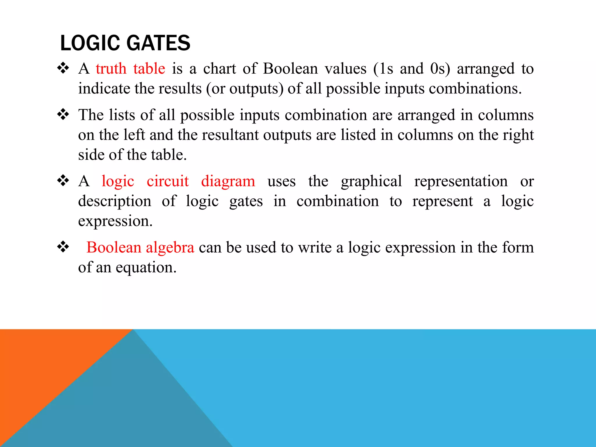
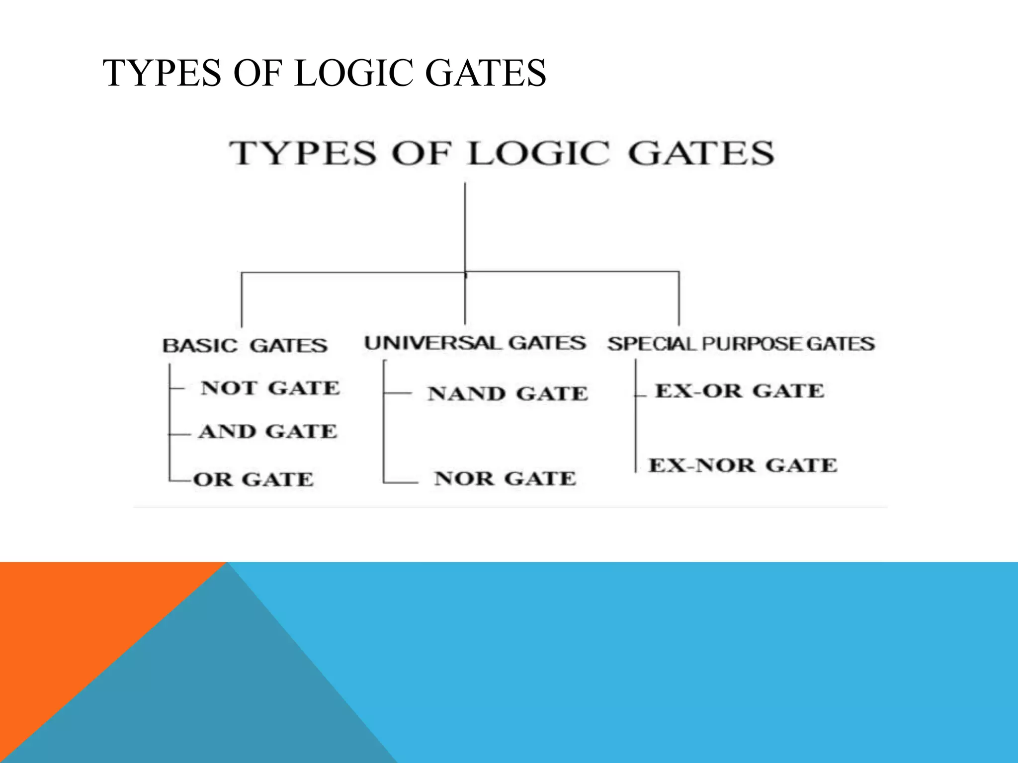
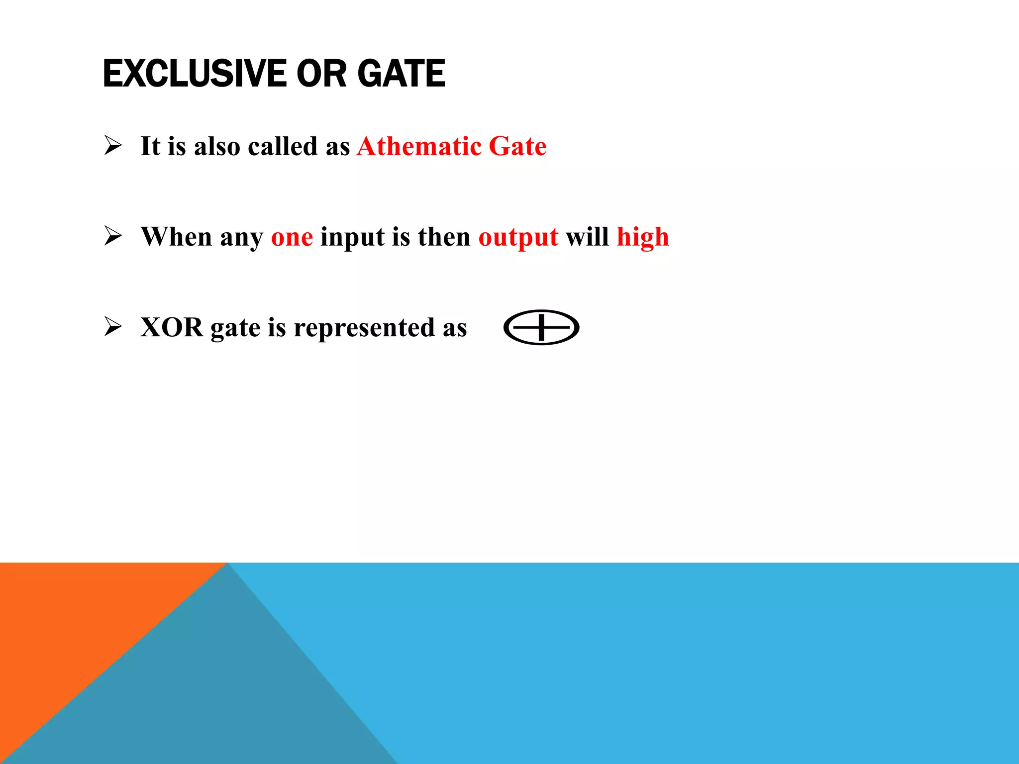
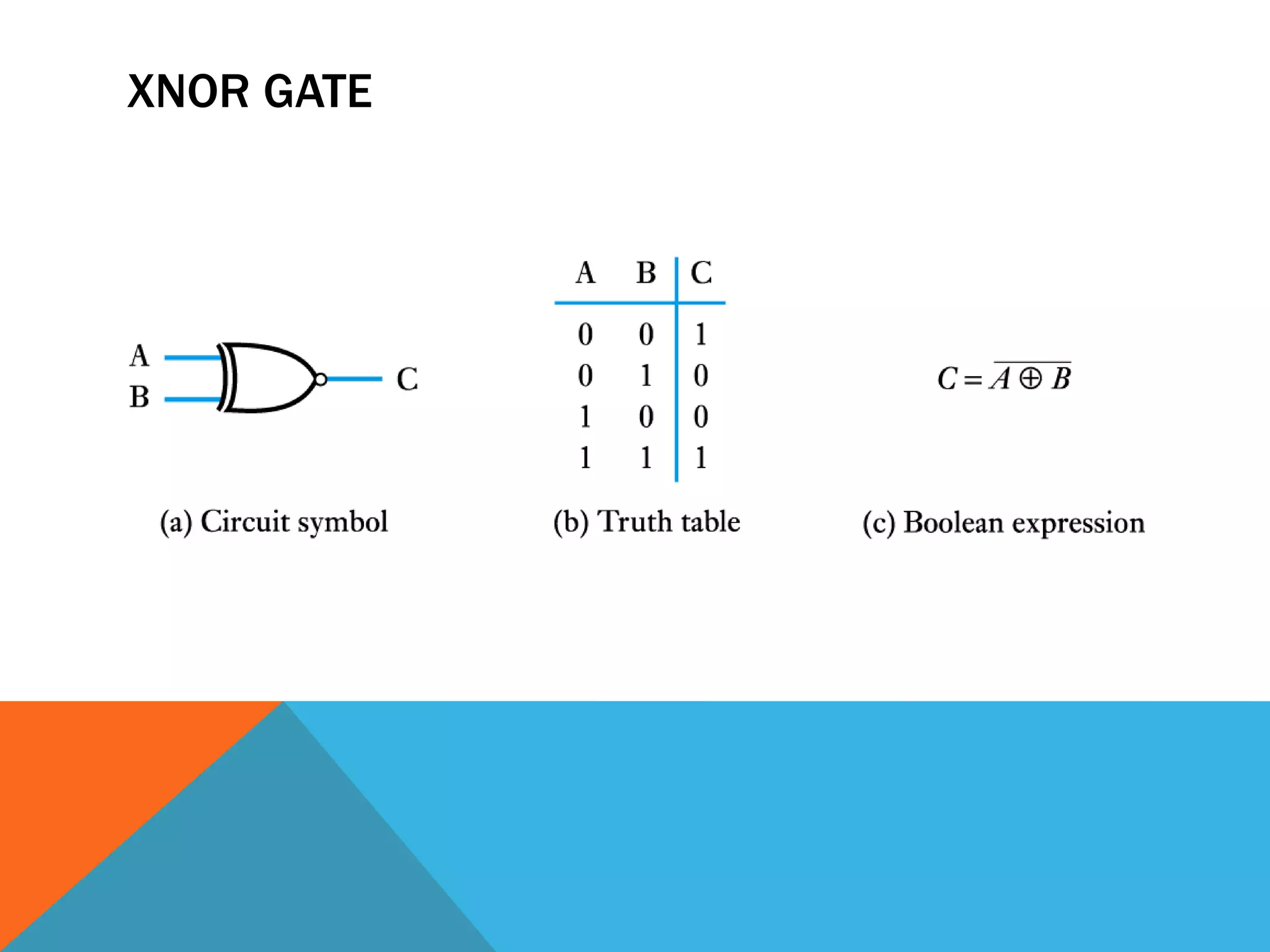
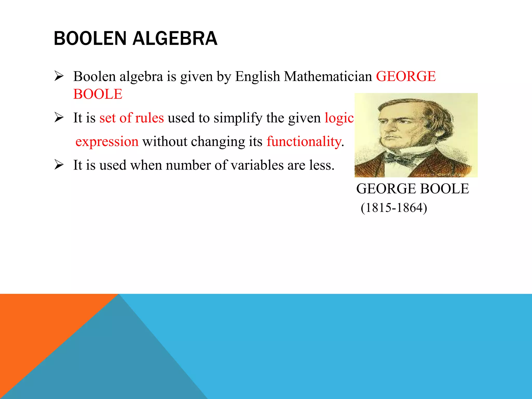
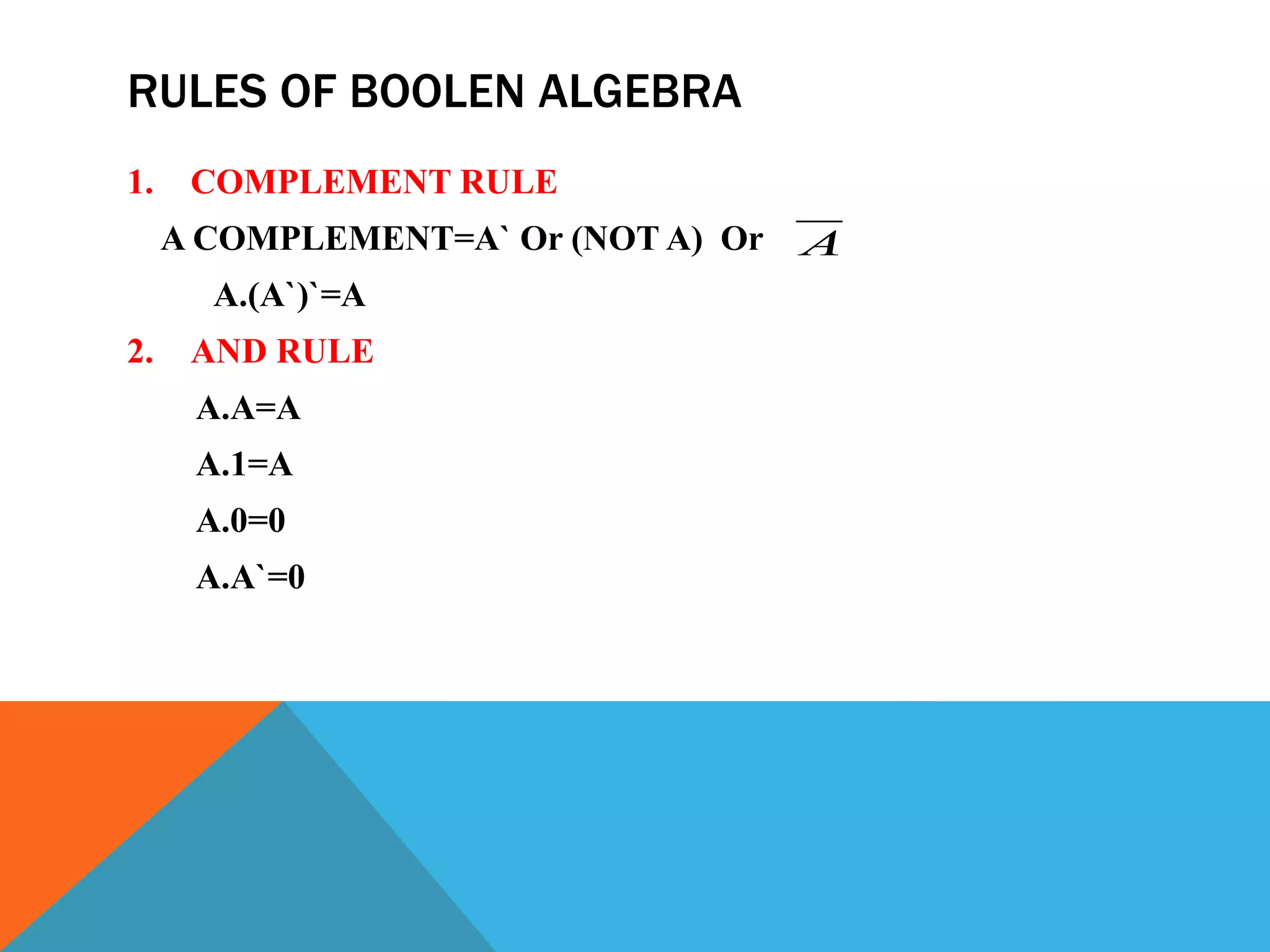
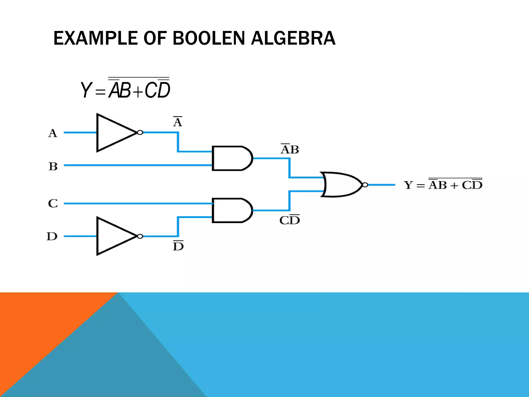
LOGIC GATES &
BOOLEN ALGEBRA
BY
M.VENKATESH
OUTLINE
 INTRODUCTION TO LOGIC GATES
 TYPES OF LOGIC GATES
 ADVANTAGES,DIADVANTAGES &
APLLICATIONS
 INTROUCTION TO BOOLEN ALGEBRA
 RULES OF BOOLEN ALGEBRA
 EXAMPLE FOR BOOLEN ALGEBRA
INTRODUCTION TO LOGIC GATES
 A logic gate is an elementary building block of a DIGITAL CIRCUIT
 Most logic gates have two inputs and one output.
 In most logic gates, the low state is approximately zero volts (0 V),
while the high state is approximately five volts positive (+5 V).
 binary conditions low for 0V or high for 1V
 There are three common ways in which to represent the working of a
logic circuit.
1. Truth Tables
2. Logic Circuit Diagram
3. Boolean Expression
LOGIC GATES
 A truth table is a chart of Boolean values (1s and 0s) arranged to
indicate the results (or outputs) of all possible inputs combinations.
 The lists of all possible inputs combination are arranged in columns
on the left and the resultant outputs are listed in columns on the right
side of the table.
 A logic circuit diagram uses the graphical representation or
description of logic gates in combination to represent a logic
expression.
 Boolean algebra can be used to write a logic expression in the form
of an equation.
TYPES OF LOGIC GATES
NOT GATE
 It Is also called as complementary or inversion gate.
 NOT gate perform the ‘~’ operation.
 It has one input and one output.
NOT GATE
NOT GATE APPLICATION
.
AND GATE
 It perform Multiplication operation.
 AND gate represented as ‘.’
 When both inputs are high then output will high
AND GATE
AND GATE APPLICATION
OR GATE
 It perform Addition operation.
 OR gate represented as ‘+’
 When both inputs are low then output will low
OR GATE
OR GATE APPLICATION
.
NAND GATE
 NAND gate Complement of AND gate.
 When both inputs are low then output will low
NAND GATE
NOR GATE
 NOR gate is Complement of OR gate
 When both inputs are low then output will be low
NOR GATE
EXCLUSIVE OR GATE
 It is also called as Athematic Gate
 When any one input is then output will high
 XOR gate is represented as 
XOR GATE
EXCLUSIVE NOR GATE
 XNOR gate is complement of XOR gate
 When both inputs are high or low then the output will high
 XNOR is represented as

XNOR GATE
ADVANTAGES
 The switching time is much faster than analog circuits.
 logic gates is less expensive
DISADVANTAGES
 Logic circuits uses more energy than other circuits like analog
circuits to accomplish the same tasks resultant circuit produces more
heat.
 For activation, logic circuits require power system i.e. portable or
battery power systems which are limited in power.
APPLICATIONS
 Personal Computers
 Mobile Phones
 Tablets
 Calculators and
 Digital Watches
BOOLEN ALGEBRA
 Boolen algebra is given by English Mathematician GEORGE
BOOLE
 It is set of rules used to simplify the given logic
expression without changing its functionality.
 It is used when number of variables are less.
GEORGE BOOLE
(1815-1864)
BOOLEN ALGEBRA
 Set of rules it is used to simply and minimize the equation.
 Logic Expression : F=A`B+BC+ABC ------(1)
---
F=A`B+BC ---------(2)
The above two functions are same
 To reduce the variable we use the map method or k-map method
 For (1) we required 5 logic gates
 For (2) we required 4 logic gates
BOOLEN ALGEBRA
RULES OF BOOLEN ALGEBRA
1. COMPLEMENT RULE
A COMPLEMENT=A` Or (NOT A) Or
A.(A`)`=A
2. AND RULE
A.A=A
A.1=A
A.0=0
A.A`=0
A
RULES
3. OR RULE
A+A=A
A+0=1
A+1=1
A+A`=1
4.DISTRUBTIVE LAW
A.(B+C) = A.B+A.C
A+(B.C) = (A+B).(A+C)
RULES
5. COMMULATATIVE LAW
A+B = B+A
A.B = B.A
6. ASSOCITATIVE LAW
(A.B).C =A.(B.C)
7. DEMORGANS LAW
(A+B)`=A`.B`
(A.B)`=A`+B`
EXAMPLE OF BOOLEN ALGEBRA
DCBAY 
Logic gates And  Boolen algebra

Logic gates And Boolen algebra

  • 1.
    LOGIC GATES & BOOLENALGEBRA BY M.VENKATESH
  • 2.
    OUTLINE  INTRODUCTION TOLOGIC GATES  TYPES OF LOGIC GATES  ADVANTAGES,DIADVANTAGES & APLLICATIONS  INTROUCTION TO BOOLEN ALGEBRA  RULES OF BOOLEN ALGEBRA  EXAMPLE FOR BOOLEN ALGEBRA
  • 3.
    INTRODUCTION TO LOGICGATES  A logic gate is an elementary building block of a DIGITAL CIRCUIT  Most logic gates have two inputs and one output.  In most logic gates, the low state is approximately zero volts (0 V), while the high state is approximately five volts positive (+5 V).  binary conditions low for 0V or high for 1V  There are three common ways in which to represent the working of a logic circuit. 1. Truth Tables 2. Logic Circuit Diagram 3. Boolean Expression
  • 4.
    LOGIC GATES  Atruth table is a chart of Boolean values (1s and 0s) arranged to indicate the results (or outputs) of all possible inputs combinations.  The lists of all possible inputs combination are arranged in columns on the left and the resultant outputs are listed in columns on the right side of the table.  A logic circuit diagram uses the graphical representation or description of logic gates in combination to represent a logic expression.  Boolean algebra can be used to write a logic expression in the form of an equation.
  • 5.
  • 6.
    NOT GATE  ItIs also called as complementary or inversion gate.  NOT gate perform the ‘~’ operation.  It has one input and one output.
  • 7.
  • 8.
  • 9.
    AND GATE  Itperform Multiplication operation.  AND gate represented as ‘.’  When both inputs are high then output will high
  • 10.
  • 11.
  • 12.
    OR GATE  Itperform Addition operation.  OR gate represented as ‘+’  When both inputs are low then output will low
  • 13.
  • 14.
  • 15.
    NAND GATE  NANDgate Complement of AND gate.  When both inputs are low then output will low
  • 16.
  • 17.
    NOR GATE  NORgate is Complement of OR gate  When both inputs are low then output will be low
  • 18.
  • 19.
    EXCLUSIVE OR GATE It is also called as Athematic Gate  When any one input is then output will high  XOR gate is represented as 
  • 20.
  • 21.
    EXCLUSIVE NOR GATE XNOR gate is complement of XOR gate  When both inputs are high or low then the output will high  XNOR is represented as 
  • 22.
  • 23.
    ADVANTAGES  The switchingtime is much faster than analog circuits.  logic gates is less expensive DISADVANTAGES  Logic circuits uses more energy than other circuits like analog circuits to accomplish the same tasks resultant circuit produces more heat.  For activation, logic circuits require power system i.e. portable or battery power systems which are limited in power.
  • 24.
    APPLICATIONS  Personal Computers Mobile Phones  Tablets  Calculators and  Digital Watches
  • 25.
    BOOLEN ALGEBRA  Boolenalgebra is given by English Mathematician GEORGE BOOLE  It is set of rules used to simplify the given logic expression without changing its functionality.  It is used when number of variables are less. GEORGE BOOLE (1815-1864)
  • 26.
    BOOLEN ALGEBRA  Setof rules it is used to simply and minimize the equation.  Logic Expression : F=A`B+BC+ABC ------(1) --- F=A`B+BC ---------(2) The above two functions are same  To reduce the variable we use the map method or k-map method  For (1) we required 5 logic gates  For (2) we required 4 logic gates
  • 27.
  • 28.
    RULES OF BOOLENALGEBRA 1. COMPLEMENT RULE A COMPLEMENT=A` Or (NOT A) Or A.(A`)`=A 2. AND RULE A.A=A A.1=A A.0=0 A.A`=0 A
  • 29.
    RULES 3. OR RULE A+A=A A+0=1 A+1=1 A+A`=1 4.DISTRUBTIVELAW A.(B+C) = A.B+A.C A+(B.C) = (A+B).(A+C)
  • 30.
    RULES 5. COMMULATATIVE LAW A+B= B+A A.B = B.A 6. ASSOCITATIVE LAW (A.B).C =A.(B.C) 7. DEMORGANS LAW (A+B)`=A`.B` (A.B)`=A`+B`
  • 31.
    EXAMPLE OF BOOLENALGEBRA DCBAY 