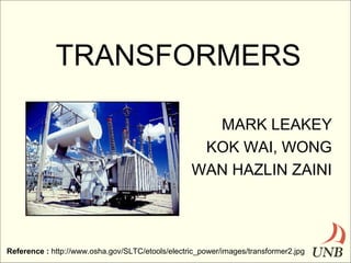
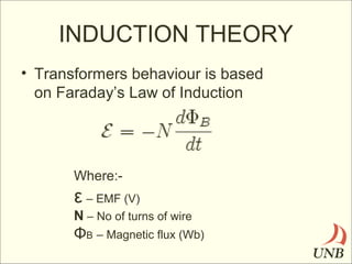
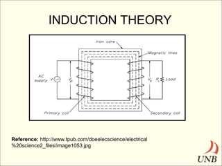
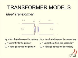
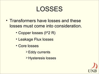
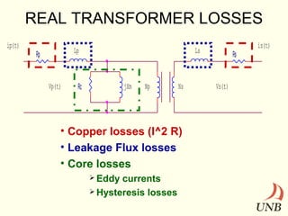
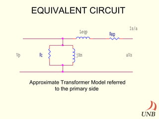
TRANSFORMERS
MARK LEAKEY
KOK WAI, WONG
WAN HAZLIN ZAINI

Reference : http://www.osha.gov/SLTC/etools/electric_power/images/transformer2.jpg
DEFINITION
• Device used to transfer energy from
primary winding to secondary winding
by electromagnetic induction.
• Based on Faraday’s Law of induction

Where:-

ε – EMF (V)
ΦB – Magnetic flux (Wb)
TRANSFORMER USES
• Impedance matching
• Electrical Isolation
• AC power transmission
 STEP-UP

Transformer

 STEP-DOWN

Transformer
HISTORY
• 1831 – Michael Faraday invented the
Induction Ring.
• 1881 – Lucien Gaulard and John Gibbs
exhibited a device called secondary
generator.
• 1885 – William Stanley developed the fist
commercially used practical device while
working for Westinghouse Electric
Company in US.
INDUCTION THEORY
• Transformers behaviour is based
on Faraday’s Law of Induction

Where:-

ε – EMF (V)
N – No of turns of wire

ΦB – Magnetic flux (Wb)
INDUCTION THEORY

Reference: http://www.tpub.com/doeelecscience/electrical
%20science2_files/image1053.jpg
TRANSFORMER MODELS
Ideal Transformer
ip(t)

Np

Ns

is(t)

+

+
Vp(t)

-

Vs(t)
-

Np = No of windings on the primary Ns = No of windings on the secondary
ip = Current into the primary

is = Current out from the secondary

Vp = Voltage across the primary

Vs = Voltage across the secondary
Primary and Secondary
Relationship
VP = NP = a = iS
VS
NS
iP
Note;

a < 1 = Step up transformer
a > 1 = Step down transformer

Voltage and current angles are NOT affected
hence, θP = θS = θ
LOSSES
• Transformers have losses and these
losses must come into consideration.
• Copper losses (I^2 R)
• Leakage Flux losses
• Core losses
 Eddy

currents

 Hysteresis

losses
REAL TRANSFORMER LOSSES
ip(t)

Lp

Rp

Vp(t)

Ls

jXm

Rc

Np

Ns

• Copper losses (I^2 R)
• Leakage Flux losses
• Core losses
 Eddy

currents
 Hysteresis losses

Rs

Vs(t)

is(t)
EQUIVALENT CIRCUIT
Leqp

Vp

Rc

Reqp

jXm

Approximate Transformer Model referred
to the primary side

Is/a

aVs
TYPES
Auto-Transformer
– Used to change a desirable voltage by only a small
amount. For example: 120/132 V
IH
VSE
+

VL
-

IL

+

ISE
NSE
VH
NC
-
TYPES
Three Phase Transformers
Three phase transformers
can be constructed in two
different ways i.e. :1. A three phase bank consists
of three single phase
transformers.
2. Three windings wrapped
around a common core.

Reference : Electric Machinery and Power System Fundamentals, Stephen J. Chapman
THREE PHASE TRANSFORMER
CONNECTIONS

Delta – wye (Δ – Y)

Wye – delta (Y- Δ)

Delta – delta (Δ – Δ)

Wye – wye (Y – Y)

Reference : Electric Machinery and Power System Fundamentals, Stephen J. Chapman
TYPES
•

Two types of special purpose transformers
used in power systems for taking
measurements.
– Potential Transformer
– Current Transformer

Reference : Electric Machinery and Power System Fundamentals, Stephen J. Chapman
EFFICIENCY
• Efficiency (η) is the ratio of the power out to
the power in of a transformer.
– η in an Ideal transformer, no power losses
• PIN = VPIP cos θP
• POUT = VSIS cos θS
• PIN = POUT = VPIP cos θP = VSIS cos θS
• SOUT = SIN = VPIP = VSIS
• ηIdeal = 100%
Efficiency for a single phase
real transformer
• As mentioned previously, losses occur in a real
transformer and these losses must be taken into
count.
• Hence, ηReal = POUT x 100%
PIN
=
POUT
x 100%
POUT + PLOSS
=
VSIS cos θS_________
VSIS cos θS + i2R + (VP/a)2
RC
VOLTAGE REGULATION
• Voltage regulation (VR) is the ability of a system
to provide near constant voltage over a wide
range of load conditions. Also it compares the V O
at no load to VO at full load.

• An Ideal transformer has a voltage regulation,
VR = 0%

Reference : http://en.wikipedia.org/wiki/Voltage_regulation

Transformers

  • 1.
    TRANSFORMERS MARK LEAKEY KOK WAI,WONG WAN HAZLIN ZAINI Reference : http://www.osha.gov/SLTC/etools/electric_power/images/transformer2.jpg
  • 2.
    DEFINITION • Device usedto transfer energy from primary winding to secondary winding by electromagnetic induction. • Based on Faraday’s Law of induction Where:- ε – EMF (V) ΦB – Magnetic flux (Wb)
  • 3.
    TRANSFORMER USES • Impedancematching • Electrical Isolation • AC power transmission  STEP-UP Transformer  STEP-DOWN Transformer
  • 4.
    HISTORY • 1831 –Michael Faraday invented the Induction Ring. • 1881 – Lucien Gaulard and John Gibbs exhibited a device called secondary generator. • 1885 – William Stanley developed the fist commercially used practical device while working for Westinghouse Electric Company in US.
  • 5.
    INDUCTION THEORY • Transformersbehaviour is based on Faraday’s Law of Induction Where:- ε – EMF (V) N – No of turns of wire ΦB – Magnetic flux (Wb)
  • 6.
  • 7.
    TRANSFORMER MODELS Ideal Transformer ip(t) Np Ns is(t) + + Vp(t) - Vs(t) - Np= No of windings on the primary Ns = No of windings on the secondary ip = Current into the primary is = Current out from the secondary Vp = Voltage across the primary Vs = Voltage across the secondary
  • 8.
    Primary and Secondary Relationship VP= NP = a = iS VS NS iP Note; a < 1 = Step up transformer a > 1 = Step down transformer Voltage and current angles are NOT affected hence, θP = θS = θ
  • 9.
    LOSSES • Transformers havelosses and these losses must come into consideration. • Copper losses (I^2 R) • Leakage Flux losses • Core losses  Eddy currents  Hysteresis losses
  • 10.
    REAL TRANSFORMER LOSSES ip(t) Lp Rp Vp(t) Ls jXm Rc Np Ns •Copper losses (I^2 R) • Leakage Flux losses • Core losses  Eddy currents  Hysteresis losses Rs Vs(t) is(t)
  • 11.
    EQUIVALENT CIRCUIT Leqp Vp Rc Reqp jXm Approximate TransformerModel referred to the primary side Is/a aVs
  • 12.
    TYPES Auto-Transformer – Used tochange a desirable voltage by only a small amount. For example: 120/132 V IH VSE + VL - IL + ISE NSE VH NC -
  • 13.
    TYPES Three Phase Transformers Threephase transformers can be constructed in two different ways i.e. :1. A three phase bank consists of three single phase transformers. 2. Three windings wrapped around a common core. Reference : Electric Machinery and Power System Fundamentals, Stephen J. Chapman
  • 14.
    THREE PHASE TRANSFORMER CONNECTIONS Delta– wye (Δ – Y) Wye – delta (Y- Δ) Delta – delta (Δ – Δ) Wye – wye (Y – Y) Reference : Electric Machinery and Power System Fundamentals, Stephen J. Chapman
  • 15.
    TYPES • Two types ofspecial purpose transformers used in power systems for taking measurements. – Potential Transformer – Current Transformer Reference : Electric Machinery and Power System Fundamentals, Stephen J. Chapman
  • 16.
    EFFICIENCY • Efficiency (η)is the ratio of the power out to the power in of a transformer. – η in an Ideal transformer, no power losses • PIN = VPIP cos θP • POUT = VSIS cos θS • PIN = POUT = VPIP cos θP = VSIS cos θS • SOUT = SIN = VPIP = VSIS • ηIdeal = 100%
  • 17.
    Efficiency for asingle phase real transformer • As mentioned previously, losses occur in a real transformer and these losses must be taken into count. • Hence, ηReal = POUT x 100% PIN = POUT x 100% POUT + PLOSS = VSIS cos θS_________ VSIS cos θS + i2R + (VP/a)2 RC
  • 18.
    VOLTAGE REGULATION • Voltageregulation (VR) is the ability of a system to provide near constant voltage over a wide range of load conditions. Also it compares the V O at no load to VO at full load. • An Ideal transformer has a voltage regulation, VR = 0% Reference : http://en.wikipedia.org/wiki/Voltage_regulation