More Related Content
Similar to Power Circuits and Transforers-Unit 7 Labvolt Student Manual
Similar to Power Circuits and Transforers-Unit 7 Labvolt Student Manual (20)
More from phase3-120A (20)
Power Circuits and Transforers-Unit 7 Labvolt Student Manual
- 1. © Festo Didactic 30328-10 297
When you have completed this unit, you will be able to explain and demonstrate
important operating characteristics of single-phase transformers. You will be able
to connect transformer windings in series-aiding and series-opposing
configurations, and demonstrate the effect that loading has on secondary
voltage. Voltage and current measurements along with transformer load curves
will be used to study transformer operation and working characteristics.
Transformers are magnetically-operated devices that can change voltage,
current, and impedance values in ac circuits. In its simplest form, a transformer
consists of two coils of wire wound on a common core of ferromagnetic material,
such as iron. One coil is called the primary winding while the other is called the
secondary winding. Transformers are probably the most universal pieces of
equipment in the electrical industry, and range in size from tiny units in transistor
radios to extremely large units weighing several tons in power distribution
stations. However, all transformers have basically the same operating principles
and characteristics, and every transformer has a primary winding for the input
power and a secondary winding for the load. Some transformers are also
designed to have more than one secondary winding. The ratio of the number of
turns of wire in the primary winding ( or ) to the number of turns of wire in
the secondary winding ( or ) is called the turns ratio. This ratio sets the
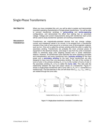
relationship between the input and output values of a transformer. Figure 7-1
shows a single-phase transformer with a turns ratio ⁄ of 1:1, connected to a
resistive load. The first exercise in this unit will show how , , , and
are related through the turns ratio.
Figure 7-1. Single-phase transformer connected to a resistive load.
Single-Phase Transformers
Unit 7
UNIT OBJECTIVE
DISCUSSION OF
FUNDAMENTALS
- 2. Unit 7 – Single-Phase Transformers Discussion of Fundamentals
298 © Festo Didactic 30328-10
When mutual inductance exists between two coils or windings, a change in
current in one coil induces a voltage in the other. Also, when the primary winding
of a transformer is connected to an ac power source, it receives electrical energy
from the source and couples the energy to the secondary winding by means of a
changing magnetic flux. This energy appears as an electromotive force (a
voltage) across the secondary winding, and when a load is connected to the
secondary, the energy is transferred to the load. This process of magnetic
coupling allows electrical energy to be transferred from one circuit to another
without any physical connection between the two, therefore providing electrical
isolation between them. Because transformers allow power at one voltage and
current level to be converted into equivalent power at some other voltage and
current level, they are indispensable in ac power distribution systems.
Because alternating current flows in the windings of a transformer, an alternating
magnetic field is created in the iron core. Active power is dissipated in the
transformer because of copper loss and iron loss, and the transformer heats
up. The resistance of the wire used in the winding causes the copper loss, and
the iron loss results from eddy currents and hysteresis, the property of magnetic
materials causing resistance to changes in magnetization.
Despite the copper and iron losses, transformers are among the most efficient
electrical devices that exist, and the apparent power at the primary is frequently
considered equal to the apparent power at the secondary. The voltage at the
secondary, however, usually varies with changes in the load, from a given value
at no load to a lesser value when the secondary is fully loaded. The amount of
variation in secondary voltage as the load applied to the secondary changes is
called transformer regulation and depends on the type of load (resistive,
inductive, or capacitive) connected to the secondary. As will be seen in this unit,
the secondary voltage can even rise above its rated value instead of decreasing.
- 3. © Festo Didactic 30328-10 299
When you have completed this exercise, you will be familiar with voltage and
current characteristics of a single-phase transformer, and able to use the
transformer turns ratio to predict the voltage and current that will flow in the
secondary winding.
The windings of a standard single-phase transformer are called the primary
winding and the secondary winding, as shown in Figure 7-1 of the Unit
Discussion. The primary winding is the power input winding and this is the side
that is connected to the ac power source. The secondary winding is connected to
the load and is physically and electrically isolated from the primary. The voltage
and current that flow in the secondary are related to the primary voltage and
current by the transformer turns ratio ⁄ (or ⁄ ) through a very simple
relationship. The ratio of primary voltage to secondary voltage equals ⁄ ,
while the ratio of primary to secondary current is equal to the inverse of the turns
ratio, ⁄ . This results in the following:
which gives:
and
which gives:
Transformers are designed with fixed ratios between primary and secondary
voltages, and are widely used to step-up (increase) or step-down (decrease) load
voltages and currents. The Single-Phase Transformer module used in these
exercises has its nominal ratings silk-screened on the front panel, and most
transformers have markings to indicate their nominal characteristics. Also, many
transformers have intermediate taps, or connection terminals on the secondary
side, so that different voltage ratios can be obtained using a single transformer.
Voltage and Current Ratios
Exercise 7-1
EXERCISE OBJECTIVE
DISCUSSION
- 4. Ex. 7-1 – Voltage and Current Ratios Procedure
300 © Festo Didactic 30328-10
Determining a transformer's voltage ratio is a relatively simple matter. With no
load connected to the secondary winding, only the small exciting current
necessary to create the magnetic flux inside the transformer flows in the primary
winding. Transformer losses are minimum and the ratio of primary to secondary
voltage equals the turns ratio. The turns ratio can be found by measuring the
unloaded secondary voltage with nominal voltage applied to the primary. The
current ratio can be evaluated by measuring the short-circuit secondary current
with a small ac voltage applied to the primary. The voltage applied to the primary
must be low enough to ensure that the nominal current in the primary winding is
not exceeded. Otherwise, the windings may overheat and be damaged.
The exciting current, which is directly related to the alternating magnetic flux,
increases in direct proportion to the applied voltage until core saturation sets in.
Saturation occurs when the applied voltage exceeds the rated value of the
primary, and then the linear relationship between the primary voltage and the
exciting current breaks down. The curve of primary voltage versus exciting
current flattens and smaller increases in primary voltage lead to larger increases
in exciting current, as shown in Figure 7-2. The exciting current is only a few
milliamperes in the EMS Single-Phase Transformer module, and generally its
value is a small percentage of the nominal current of a transformer.
Figure 7-2. Saturation curve of a transformer.
EQUIPMENT REQUIRED
Refer to the Equipment Utilization Chart in Appendix C to obtain the list of
equipment required for this exercise.
High voltages are present in this laboratory exercise. Do not make or modify any
banana jack connections with the power on unless otherwise specified.
1. Install the Power Supply, data acquisition module, and Single-Phase
Transformer module in the EMS Workstation.
PROCEDURE
- 5. Ex. 7-1 – Voltage and Current Ratios Procedure
© Festo Didactic 30328-10 301
2. Make sure that the main switch of the Power Supply is set to the O (OFF)
position, and the voltage control knob is turned fully counterclockwise. Set
the voltmeter select switch to the 4-N position, then make sure that the
Power Supply is connected to a three-phase wall receptacle.
3. Make sure that the data acquisition module is connected to a USB port of the
computer.
Connect the POWER INPUT of the data acquisition module to the
24 V - AC output of the Power Supply. Set the 24 V - AC power switch to
the I (ON) position.
4. Start the Data Acquisition software (LVDAC or LVDAM). Open setup
configuration file ES17-1.dai.
Make sure that the continuous refresh mode is selected.
5. Set up the transformer circuit shown in Figure 7-3. Connect meter inputs E1
and I1 as shown and use E2 to measure the different secondary voltages.
Figure 7-3. Single-phase transformer measurements.
Local ac power network
(V)
Voltage
(V)
Frequency
(Hz)
120 60 120
Is = IPRI
- 6. Ex. 7-1 – Voltage and Current Ratios Procedure
302 © Festo Didactic 30328-10
6. Turn on the main Power Supply and adjust the voltage control knob for the
value of voltage given in Figure 7-3. Measure the transformer primary
current and the different voltages across the various terminals of the
transformer secondary windings, listed below. Change the connections of
input E2 to measure each secondary voltage, making sure to turn off the
Power Supply before modifying the connections of input E2. After recording
the measured values, turn the voltage control knob fully counterclockwise,
then turn off the Power Supply.
A
V
V
V
V
V
V
V
V
- 7. Ex. 7-1 – Voltage and Current Ratios Procedure
© Festo Didactic 30328-10 303
7. Do the secondary voltages compare well with the rated values written on the
front panel?
Yes No
8. The transformer windings between terminals 1 and 2, and between
terminals 5 and 6, each have 500 turns of wire. The number of turns in the
winding between terminals 3 and 4 is 865. Calculate the turns ratios between
the primary and secondary windings for each case.
9. Using the measured values in step 6, compare these transformer turns ratios
with the corresponding voltage ratios. Are they approximately the same?
Yes No
10. Make sure that the power supply is turned off and the voltage control knob is
set to 0% (turned fully counterclockwise). Connect meter input I2 as shown in
Figure 7-4 and note that it short-circuits secondary winding 5-6. Select setup
configuration file ES17-2.dai. Turn on the power and slowly adjust the
voltage control knob to obtain the value of current given in Figure 7-4.
- 8. Ex. 7-1 – Voltage and Current Ratios Procedure
304 © Festo Didactic 30328-10
Figure 7-4. Determining the ratio of primary current to secondary current.
11. Record the values of primary voltage and current, and the value of the short-
circuit secondary current in winding 5-6.
V
A
A
Local ac power network
(A)
Voltage
(V)
Frequency
(Hz)
120 60 0.40
Is = IPRI
- 9. Ex. 7-1 – Voltage and Current Ratios Procedure
© Festo Didactic 30328-10 305
12. Return the voltage control knob to zero and turn off the Power Supply.
Calculate the ratio of primary current to secondary current.
13. Is the ratio approximately equal to ⁄ [ ⁄ ]?
Yes No
14. Connect meter input I2 so that it now short-circuits secondary terminals 3-4.
Turn on the Power Supply and slowly adjust the voltage control knob for the
same value of primary current used in step 10. Once again, record the
values of primary voltage and current, and the secondary winding current.
V
A
A
15. Return the voltage control knob to zero and turn off the Power Supply. Again,
calculate the ratio of primary current to secondary current. Is it equal
to ⁄ [ ⁄ ]?
Yes No
- 10. Ex. 7-1 – Voltage and Current Ratios Procedure
306 © Festo Didactic 30328-10
16. Set up the transformer circuit shown in Figure 7-5. It will be used to show
how exciting current is affected when the transformer core becomes
saturated. Since the exciting current is so small, the corresponding
voltage across a sense resistor ( ) will be used to illustrate its variation.
Connect the transformer primary terminals to Power Supply terminals 4
and 5 through sense resistor . Connect meter inputs E1, E2, and E3 to
measure the transformer voltages, , , and , respectively. Connect
meter input I1 to measure the primary current, .
Figure 7-5. Effect of core saturation on exciting current.
17. Open configuration file ES17-3.dai. Turn on the Power Supply and use the
voltage control knob to obtain values for (E2) equally spaced at about
10% intervals over the complete control knob range. For each voltage
adjustment, use the Data Table to record the measured values.
Do not leave high currents circulate through the transformer primary coil over a long
period of time. Take all your measurements requiring a primary current higher than the
transformer coil nominal value within two minutes. Let the transformer cool down for
15 minutes after the Power Supply is turned off.
Local ac power network
(Ω)
Voltage
(V)
Frequency
(Hz)
120 60 100
Is = IPRI
- 11. Ex. 7-1 – Voltage and Current Ratios Procedure
© Festo Didactic 30328-10 307
Transformer voltages.
Sensed voltage ( )
(V)
Primary voltage ( )
(V)
Secondary voltage ( )
(V)
18. When all measured values have been recorded, turn the voltage control knob
fully counterclockwise, and turn off the Power Supply.
- 12. Ex. 7-1 – Voltage and Current Ratios Procedure
308 © Festo Didactic 30328-10
19. Display the Graph window, select E1 ( ) as the X-axis parameter, and
E2 ( ) as the Y-axis parameter. Make sure the line graph format and the
linear scale are selected. Observe the curve of primary voltage versus
exciting current, represented by E1. Does the exciting current increase more
rapidly after the rated voltage is exceeded?
Yes No
Primary voltage versus sensed voltage.
20. Does the curve illustrate that the transformer core becomes saturated?
Yes No
21. Review the measured data to determine how the primary-to-secondary
voltage ratio was affected when the transformer core became saturated.
0
20
40
60
80
100
120
140
160
180
200
0 01 20 03 04 05 60 07 08 90 100
Sensed voltage [proportional to exciting current] (V)
Primaryvoltage(V)
- 13. Ex. 7-1 – Voltage and Current Ratios Conclusion
© Festo Didactic 30328-10 309
22. Ensure that the Power Supply is turned off, and that the voltage control knob
is turned fully counterclockwise. Remove all leads and cables.
In this exercise, you measured the primary and secondary voltages in a single-
phase transformer and confirmed that the ratio of primary-to-secondary voltage
equals the transformer turns ratio ⁄ . Measurements of primary and
secondary currents showed that the ratio of currents was equal to the inverse of
the turns ratio. You also observed the phenomenon of core saturation, and saw
that transformer saturation did not affect the voltage ratio.
1. The turns ratio for a transformer with 225 turns of wire in its primary winding
and 675 turns in the secondary is
a. 1:3
b. 3:1
c. ⁄
d. ⁄
2. The short-circuit secondary current in a transformer is 5 A. What is the
primary current if the transformer turns ratio is 1:4?
a. 20 A
b. 1.25 A
c. 2.0 A
d. 0.8 A
3. Transformer saturation occurs when the
a. primary current is greater than the rated value.
b. secondary winding is short-circuited.
c. secondary voltage is lower than the rated value.
d. primary voltage is greater than the rated value.
CONCLUSION
REVIEW QUESTIONS
- 14. Ex. 7-1 – Voltage and Current Ratios Review Questions
310 © Festo Didactic 30328-10
4. When 200 V is applied to the primary winding of a step-up transformer that
doubles the primary voltage, how much current will flow in a 100-Ω load
resistor connected across the secondary winding?
a. 1 A
b. 2 A
c. 3 A
d. 4 A
5. Why is it necessary to apply a low voltage to the primary winding instead of
the rated voltage when evaluating the current ratio of a transformer?
a. To ensure that rated current will flow in the secondary.
b. To ensure that the current rating of the primary is not
exceeded.
c. To ensure that the voltage rating of the secondary is
respected.
d. To ensure that exciting current is maximum.
- 15. © Festo Didactic 30328-10 311
When you have completed this exercise, you will be able to determine and use
transformer polarities to properly connect separate windings so that the voltages
add (series-aiding) or subtract (series-opposing).
When the primary winding of a transformer is energized by an ac source, an
alternating magnetic flux is established in the iron core. This alternating flux links,
or couples, the turns of each winding on the transformer and induces ac voltages
in the windings. Polarity might seem to be of minor importance for transformers
since they are ac devices. However, when two or more windings are connected
together, their relative instantaneous polarities have a significant effect on the
resulting net voltage. If the voltage in one winding is at its maximum positive
peak when the voltage in another winding is at its maximum negative peak, that
is, they are 180° out of phase, they will oppose each other and the resulting
voltage will be the difference between the two. For this reason, standards have
been adopted for marking the polarity of transformer leads. In North American
standards, the high-voltage leads are identified H1 and H2, and low voltage leads
are marked X1 and X2. When H1 is instantaneously positive, X1 is also
instantaneously positive. This system of marking allows transformers to be
properly connected so that winding voltages will add or subtract as desired.
Other types of markings are also used to identify the polarity of transformers, and
transformer terminals could be marked with dots, crosses, numerals, or other
convenient symbols. In Figure 7-6, dots have been used in the schematic
drawing of a transformer and its windings.
Figure 7-6. Transformer polarity markings.
Transformer Polarity
Exercise 7-2
EXERCISE OBJECTIVE
DISCUSSION
- 16. Ex. 7-2 – Transformer Polarity Discussion
312 © Festo Didactic 30328-10
When we speak of the polarity of transformer windings, we are identifying all
terminals that have the same polarity, either negative or positive, at any instant in
time. The dots used in Figure 7-6 indicate that at a given instant in time, when
terminal 1 is positive with respect to terminal 2, then
terminal 3 is positive with respect to terminal 4;
terminal 6 is positive with respect to terminal 5;
terminal 7 is positive with respect to terminal 8;
terminal 10 is positive with respect to terminal 9.
Note that a terminal cannot be positive by itself, it can only be positive with
respect to another terminal. Therefore, terminals 1, 3, 6, 7 and 10 are all positive
with respect to terminals 2, 4, 5, 8 and 9 at any given instant in time.
When two dc cells or batteries are connected in series to obtain a higher output
voltage, the positive terminal of one battery must be connected to the negative
terminal of the other. In the same manner, if two transformer windings are to be
connected in series so that their voltages add, the marked terminal of one of the
windings must be connected to the unmarked terminal of the other winding.
Conversely, if two transformer windings are to be connected in series so that
their voltages subtract, the marked terminal of one of the windings must be
connected to the marked terminal of the other winding.
It is also very important to respect polarities when connecting transformer
windings having the same nominal voltage in parallel to share the current
supplied to a load. Connecting transformer windings in parallel with opposite
polarities will cause a large current to flow in the windings. An exercise in the
next unit of this manual deals with parallel connections of transformers.
There are two methods for determining the polarity of a transformer, one using a
dc source, the other an ac source. In the dc method, a dc voltmeter is connected
across the secondary winding and a small dc voltage is applied to the primary.
The direction in which the voltmeter pointer temporarily deflects when power is
turned on will indicate the polarity of the secondary winding. The pointer will
temporarily deflect to the right if the secondary winding terminal to which the
voltmeter positive probe is connected has the same polarity as the primary
winding terminal to which the positive side of the source is connected. If it
deflects to the left, the primary and secondary terminals have opposite polarities.
With the ac source method, an ac voltage is connected to the primary winding
which is temporarily connected in series with the secondary. The voltage across
the series combination will be less than the applied voltage if the two terminals
that are interconnected have the same polarity. If the voltage is greater, the
interconnected terminals have opposite polarities. Figure 7-7 illustrates both
methods of determining transformer polarity.
- 17. Ex. 7-2 – Transformer Polarity Procedure
© Festo Didactic 30328-10 313
Figure 7-7. Methods for determining transformer polarity.
EQUIPMENT REQUIRED
Refer to the Equipment Utilization Chart in Appendix C to obtain the list of
equipment required for this exercise.
High voltages are present in this laboratory exercise. Do not make or modify any
banana jack connections with the power on unless otherwise specified.
1. Install the Power Supply, data acquisition module, and Single-Phase
Transformer module in the EMS Workstation.
2. Make sure that the main switch of the Power Supply is set to the O (OFF)
position, and the voltage control knob is turned fully counterclockwise. Set
the voltmeter select switch to the 4-N position, then make sure that the
Power Supply is connected to a three-phase wall receptacle.
3. Make sure that the data acquisition module is connected to a USB port of the
computer.
Connect the POWER INPUT of the data acquisition module to the
24 V - AC output of the Power Supply. Set the 24 V - AC power switch to
the I (ON) position.
4. Start the Data Acquisition software (LVDAC or LVDAM). Open setup
configuration file ES17-4.dai.
Make sure that the continuous refresh mode is selected.
PROCEDURE
- 18. Ex. 7-2 – Transformer Polarity Procedure
314 © Festo Didactic 30328-10
5. Set up the transformer circuit shown in Figure 7-8. Connect terminals 1 and 5
together as shown. Note that the ac input power in this circuit is connected at
winding 3-4.
Figure 7-8. Transformer windings connected in series.
6. Turn on the Power Supply and adjust the voltage control knob to set
voltage at exactly 50% of the rated voltage for winding 3-4. Note that the
rated voltage is the sum of the intermediate winding voltages between
terminals 3 and 4. Measure and record the voltages at transformer windings
1-2, 5-6, and 2-6. Note that voltage is obtained by using the metering
function E2 + E3.
V
V
V
7. Are the windings connected in series-aiding, or series-opposing?
a The voltage measured between terminals 2 and 6 is normally around zero
volts, meaning that the windings are connected so that the voltages subtract
from each other. Transformer polarity can be determined in this manner
because the voltage across two interconnected windings will be less than the
applied voltage when the interconnected terminals have the same polarity.
- 19. Ex. 7-2 – Transformer Polarity Procedure
© Festo Didactic 30328-10 315
8. Return the voltage control knob to zero and turn off the Power Supply.
Disconnect terminals 1 and 5, and connect terminals 1 and 6 together.
Reverse connections to meter input E3. If this new connection is series-
aiding, what will be the value of voltage when the same voltage as that
in step 6 is applied to winding 3-4?
9. Open configuration file ES17-5.dai. Turn on the Power Supply and once
again set voltage at exactly 50% of the rated voltage for winding 3-4.
Measure and record the voltages at transformer windings 1-2, 5-6, and 2-5
indicated on the meters. Note that voltage is obtained by using the
metering function E2 + E3.
V
V
V
10. Is the value obtained for voltage the same as predicted in step 8?
Yes No
11. Return the voltage control knob to zero, turn off the Power Supply and
remove the connection between terminals 1 and 6. What are the two
voltages which can be obtained across the series combination of
windings 3-4 and 1-2 when the same voltage as that in step 9 is applied to
winding 3-4?
- 20. Ex. 7-2 – Transformer Polarity Procedure
316 © Festo Didactic 30328-10
12. Connect terminals 1 and 4 together, turn on the Power Supply and set
voltage at exactly 50% of the rated voltage for winding 3-4. Open
configuration file ES17-6.dai. Measure and record the voltages at transformer
windings 1-2, and 2-3, using the meters.
V
V
13. Return the voltage control knob to zero and turn off the Power Supply.
Disconnect terminals 1 and 4, and connect terminals 1 and 3 together.
Interchange the connections at input E2 of the data acquisition module.
14. Turn on the Power Supply and set voltage at exactly 50% of the rated
voltage for winding 3-4. Open configuration file ES17-7.dai. Measure and
record the voltage at transformer winding 2-4.
V
15. How do the results of steps 12 and 14 compare with the predictions in
step 11?
16. Which sets of terminals have the same polarity, 1 and 3, 2 and 4, 1 and 4, or
2 and 3?
17. Ensure that the Power Supply is turned off, and that the voltage control knob
is turned fully counterclockwise. Remove all leads and cables.
- 21. Ex. 7-2 – Transformer Polarity Conclusion
© Festo Didactic 30328-10 317
In this exercise, you determined transformer polarity using the ac voltage
method. When connecting transformer windings in series, you observed that the
winding voltages subtract when winding terminals of the same polarity are
connected together. Conversely, you observed that the winding voltages add
when winding terminals of opposite polarities are connected together. This is
similar to connecting batteries in series to obtain higher voltages.
1. Can different transformer windings be connected together for higher voltages
if the terminals are not marked?
a. Yes, but the polarity must be determined experimentally
beforehand.
b. No.
c. Only if the windings are on the primary side of the
transformer.
d. Only if the current is less than 1 A.
2. Two of four secondary terminals on a transformer are marked with a cross. If
these two terminals are connected together, the secondary windings are
a. connected in series-opposing.
b. connected in series-aiding.
c. connected to increase the resulting voltage.
d. both b and c.
3. Is it possible for a voltmeter connected across the secondary windings of a
transformer with three windings having nominal voltages of 50 V, 125 V, and
75 V to measure zero volts, even though rated voltage is applied to the
primary winding?
a. No, there must be something wrong with the voltmeter.
b. Yes, if the 50-V and 75-V windings are connected to
oppose the 125-V winding.
c. Yes, if the 50-V and 75-V windings are connected to aid the
125-V winding.
d. No, the transformer must be damaged.
CONCLUSION
REVIEW QUESTIONS
- 22. Ex. 7-2 – Transformer Polarity Review Questions
318 © Festo Didactic 30328-10
4. Two methods of determining the polarity of transformer windings are
a. the resistive method and the inductive method.
b. the series-opposing method and the series-aiding method.
c. the dc method and the ac method.
d. the experimental method and the theoretical method.
5. To properly connect transformer windings for higher voltage, it is necessary
a. to know their ratings.
b. to know the maximum winding current.
c. to know the type of core material.
d. to know the polarity of the windings.
- 23. © Festo Didactic 30328-10 319
When you have completed this exercise, you will be able to determine the
voltage regulation of a transformer with varying loads, and discuss capacitive and
inductive loading on transformer regulation. Voltage and current measurements
will be used to produce load regulation curves.
The load on a large power transformer in a sub-station will vary from a very small
value in the early hours of the morning to a very high value during the heavy
peaks of maximum industrial and commercial activity. The transformer secondary
voltage will vary somewhat with the load, and because motors, incandescent
lamps, and heating devices are all quite sensitive to voltage changes,
transformer regulation is of considerable importance. The secondary voltage also
depends upon whether the power factor of the load is leading, lagging, or unity.
Therefore, it should be known how the transformer will behave (its voltage
regulation) when connected to a capacitive, an inductive, or a resistive load.
Transformer voltage regulation in percent is determined with the following
formula:
Voltage regulation % 100
where is the no-load secondary voltage.
is the full-load secondary voltage.
The result (a percentage value) obtained gives an indication of transformer
behavior under load. The smaller the voltage regulation percentage, the smaller
the secondary voltage variation with load, and the better the voltage regulation.
Note that is measured with the secondary winding open while is
measured when nominal current flows in the secondary winding.
Several factors affect a transformer's operation. The resistance and inductive
reactance of its windings cause internal voltage drops that vary with the amount
of current flowing in the windings. If the secondary is lightly loaded, current
through the winding resistance and reactance is small and the internal voltage
drops are not significant. As the load increases, current and internal voltage
drops also increase. If a transformer were perfectly ideal, its windings would have
neither resistance nor inductive reactance to cause voltage drops. Such a
transformer would have perfect regulation under all load conditions and the
secondary voltage would remain absolutely constant. But practical transformer
coils are made of real wire, and thereby, have resistance and inductive
reactance. Therefore, the primary and secondary windings have an overall
resistance , and an overall reactance . The simplified equivalent circuit of a
practical transformer with a 1:1 turns ratio can be approximated by the circuit
shown in Figure 7-9. The actual transformer terminals are , on the primary
side, and , on the secondary side.
Transformer Regulation
Exercise 7-3
EXERCISE OBJECTIVE
DISCUSSION
- 24. Ex. 7-3 – Transformer Regulation Procedure
320 © Festo Didactic 30328-10
Figure 7-9. Simplified equivalent circuit of a practical transformer.
In this equivalent circuit, the practical transformer is shown to be made up of an
ideal transformer in series with an impedance consisting of and that
represents the imperfections of the transformer. When a load ( ) is connected to
the secondary winding terminals (terminals and ), a series ac circuit
consisting of the secondary winding of the ideal transformer, , , and is
obtained. Analysis of this series ac circuit shows that when the load is either
resistive or inductive, the load voltage decreases continuously as the load
increases (as the secondary current increases). Furthermore, when the load is
capacitive, the load voltage increases to a maximum as the load increases from
zero (no load condition), and then, the load voltage decreases as the load
continues to increase.
EQUIPMENT REQUIRED
Refer to the Equipment Utilization Chart in Appendix C to obtain the list of
equipment required for this exercise.
High voltages are present in this laboratory exercise. Do not make or modify any
banana jack connections with the power on unless otherwise specified.
1. Install the Power Supply, data acquisition module, Single-Phase
Transformer, Resistive Load, Capacitive Load, and Inductive Load modules
in the EMS Workstation.
2. Make sure that the main switch of the Power Supply is set to the O (OFF)
position, and the voltage control knob is turned fully counterclockwise. Set
the voltmeter select switch to the 4-N position, then make sure that the
Power Supply is connected to a three-phase wall receptacle.
3. Make sure that the data acquisition module is connected to a USB port of the
computer.
Connect the POWER INPUT of the data acquisition module to the
24 V - AC output of the Power Supply. Set the 24 V - AC power switch to
the I (ON) position.
PROCEDURE
- 25. Ex. 7-3 – Transformer Regulation Procedure
© Festo Didactic 30328-10 321
4. Start the Data Acquisition software (LVDAC or LVDAM). Open setup
configuration file ES17-8.dai.
Make sure that the continuous refresh mode is selected.
5. Set up the transformer loading circuit shown in Figure 7-10. Make sure that
all switches on the Resistive, Capacitive, and Inductive Load modules are
open, and connect meter inputs E1, E2, I1, and I2 as shown in the figure.
Different load values will be used to examine how the secondary (load)
voltage changes as transformer loading changes.
Figure 7-10. Transformer with a variable load.
6. Turn on the main Power Supply and adjust the voltage control knob to obtain
the value of voltage given in Figure 7-10. With no load on the transformer
(all switches open on the load module), record the measured values of ,
, , and in the Data Table.
7. Adjust the switches on the Resistive Load module to successively obtain the
resistance values given in Table 7-1. For each resistance value, record the
measured values as in step 6. When all values have been recorded, turn the
voltage control knob fully counterclockwise, and turn off the Power Supply.
Local ac power network
(V) (Ω)
Voltage
(V)
Frequency
(Hz)
120 60 120 ∞
- 26. Ex. 7-3 – Transformer Regulation Procedure
322 © Festo Didactic 30328-10
Table 7-1. Values for , , and .
Local ac power network
, ,
(Ω)
, ,
(Ω)
, ,
(Ω)
, ,
(Ω)
, ,
(Ω)
Voltage
(V)
Frequency
(Hz)
120 60 1200 600 400 300 240
Transformer with a variable resistive load.
Primary voltage
( )
(V)
Secondary voltage
( )
(V)
Primary current
( )
(A)
Secondary current
( )
(A)
8. Display the Graph window, select E2 ( ) as the Y-axis parameter, and
I2 ( ) as the X-axis parameter. Make sure the line graph format and the
linear scale are selected. Observe the curve of secondary voltage versus
current. What happens to the secondary voltage as the resistive load
increases, i.e. load resistance decreases?
a To make it easier to compare the curves obtained with different loads, hard
copies of the graphs in steps 8, 13, and 17 can be printed using the Print
button on the Tool Bar.
- 27. Ex. 7-3 – Transformer Regulation Procedure
© Festo Didactic 30328-10 323
9. Calculate the voltage regulation using the no-load ( ∞) and full-load
( minimum value) output voltages.
100 %
10. Clear the Data Table, then replace the Resistive Load module in the circuit of
Figure 7-10 with the Inductive Load module.
11. Turn on the Power Supply and adjust the voltage control knob to obtain the
value of voltage given in Figure 7-10. With no load on the transformer (all
switches open on the load module), record the measured values of , ,
, and in the Data Table.
0
20
40
60
80
100
120
140
0.00 0.05 0.10 0.15 0.20 0.25 0.30 0.35 0.40 0.45 0.50
Secondary current [load current] (A)
Secondary voltage versus current (resistive load).
Secondaryvoltage(V)
- 28. Ex. 7-3 – Transformer Regulation Procedure
324 © Festo Didactic 30328-10
12. Adjust the switches on the Inductive Load module to successively obtain the
reactance values given in Table 7-1. For each reactance value, record the
measured values as in step 11. When all values have been recorded, turn
the voltage control knob fully counterclockwise, and turn off the Power
Supply.
Transformer with a variable inductive load.
Primary voltage
( )
(V)
Secondary voltage
( )
(V)
Primary current
( )
(A)
Secondary current
( )
(A)
13. Display the Graph window, select E2 ( ) as the Y-axis parameter, and
I2 ( ) as the X-axis parameter. Make sure the line graph format and the
linear scale are selected. Observe the curve of secondary voltage versus
current. How does the secondary voltage vary as the inductive load
increases?
0
25
50
75
100
125
150
0.00 0.05 0.10 0.15 0.20 0.25 0.30 0.35 0.40 0.45 0.50
Secondary current [load current] (A)
Secondary voltage versus current (inductive load).
Secondaryvoltage(V)
- 29. Ex. 7-3 – Transformer Regulation Procedure
© Festo Didactic 30328-10 325
14. Clear the Data Table, then replace the Inductive Load module in the circuit
of Figure 7-10 with the Capacitive Load module.
15. Turn on the Power Supply and adjust the voltage control knob to obtain the
value of voltage given in Figure 7-10. With no load on the transformer (all
switches open on the load module), record the measured values of , ,
, and in the Data Table.
16. Adjust the switches on the Capacitive Load module to successively obtain
the reactance values given in Table 7-1. For each reactance value, record
the measured values as in step 15. When all values have been recorded,
turn the voltage control knob fully counterclockwise, and turn off the Power
Supply.
Transformer with a variable capacitive load.
Primary voltage
( )
(V)
Secondary voltage
( )
(V)
Primary current
( )
(A)
Secondary current
( )
(A)
- 30. Ex. 7-3 – Transformer Regulation Procedure
326 © Festo Didactic 30328-10
17. Display the Graph window, select E2 ( ) as the Y-axis parameter,
and I2 ( ) as the X-axis parameter. Make sure the line graph format and
the linear scale are selected. Observe the curve of secondary voltage versus
current. How does the secondary voltage vary as the capacitive load
increases?
18. What differences do you observe between the three load curves?
19. Ensure that the Power Supply is turned off, and that the voltage control knob
is turned fully counterclockwise. Remove all leads and cables.
0
25
50
75
100
125
150
0.00 0.05 0.10 0.15 0.20 0.25 0.30 0.35 0.40 0.45 0.50 0.55 0.60
Secondary current [load current] (A)
Secondary voltage versus current (capacitive load).
Secondaryvoltage(V)
- 31. Ex. 7-3 – Transformer Regulation Conclusion
© Festo Didactic 30328-10 327
In this exercise, you examined the voltage regulation of a transformer, and saw
that the secondary voltage varied as the load placed on the transformer changed.
Load variation curves for resistive, inductive, and capacitive loads were plotted.
These curves showed that under resistive or inductive loading conditions, the
secondary voltage decreases as the load increases, and that under capacitive
loading conditions, the secondary voltage can rise above its nominal value. Also,
inductive loading caused greater voltage drops than resistive loading, hence
poorer regulation.
1. Transformer regulation can be determined with the formula
a. 100 ⁄
b. 100 ⁄
c. 100 ⁄
d. 100 ⁄
2. What is the transformer regulation if the no-load and full-load voltages are
100 V and 95 V respectively?
a. 105%
b. 10.5%
c. 95%
d. 5%
3. The secondary voltage can rise above its rated value when the load is
a. resistive.
b. capacitive.
c. inductive.
d. an RL series combination.
4. The voltage measured across the secondary winding of a transformer with no
load connected is 150 V. This voltage drops to 147 V when the secondary
current is equal to the nominal full-load current. What is the transformer
regulation?
a. 90%
b. 3%
c. 2%
d. 6%
CONCLUSION
REVIEW QUESTIONS
- 32. Ex. 7-3 – Transformer Regulation Review Questions
328 © Festo Didactic 30328-10
5. Transformer regulation
a. depends on the type of load connected at the secondary.
b. is independent of the load connected at the secondary.
c. can only be determined with no load on the secondary.
d. depends on the voltage applied to the primary.
- 33. Unit 7 – Single-Phase Transformers Unit Test
© Festo Didactic 30328-10 329
Unit Test
1. A transformer primary has 320 turns of wire and the secondary voltage
measures 160 V when 40 V is applied to the primary. The voltage ratio is
therefore
a. 1: 8
b. 2: 1
c. 1: 4
d. 1: 2
2. The short-circuit secondary current in a transformer is 2 A. What is the
primary current if the transformer turns ratio is 2: 5?
a. 2 A
b. 5 A
c. 2.5 A
d. 0.8 A
3. When the primary voltage exceeds its rated value
a. transformer operation is enhanced.
b. transformer operation suffers because of core saturation.
c. by more than double, transformer operation improves.
d. the primary current decreases.
4. To evaluate the current ratio of a transformer,
a. rated voltage must be applied to the primary.
b. rated current must flow in the primary.
c. a very low primary voltage must be applied.
d. the primary must be short-circuited.
- 34. Unit 7 – Single-Phase Transformers Unit Test
330 © Festo Didactic 30328-10
5. When unmarked transformer terminals are connected together, this usually
means that the windings are connected
a. in series-aiding.
b. in series-opposing.
c. to increase the resulting voltage.
d. both a and c.
6. Voltage regulation of a transformer can be determined with the formula
a. 100 ⁄
b. 100 ⁄
c. 100 ⁄
d. 100 ⁄
7. What is the no-load voltage when the full-load secondary voltage is 108 V
and transformer regulation is 10%?
a. 98 V
b. 120 V
c. 12 V
d. 118.8 V
8. A capacitive load can cause the secondary voltage of a transformer to
a. rise above its rated value.
b. steadily decrease with increasing load.
c. steadily increase with decreasing load.
d. none of the above.
9. What is the transformer regulation if the no-load and full-load voltages are
2 kV and 1.95 kV, respectively?
a. 5%
b. 2.5%
c. 3.6%
d. 0.25%
- 35. Unit 7 – Single-Phase Transformers Unit Test
© Festo Didactic 30328-10 331
10. The type of load connected to the secondary of a transformer has
a. a small effect on transformer regulation.
b. a significant effect on transformer regulation.
c. no effect on transformer regulation.
d. none of the above.
- 37. © Festo Didactic 30328-10 411
The following table gives impedance values which can be obtained using either
the Resistive Load, Model 8311, the Inductive Load, Model 8321, or the
Capacitive Load, Model 8331. Figure B-1 shows the load elements and
connections. Other parallel combinations can be used to obtain the same
impedance values listed.
Table B-1. Impedance table for the load modules.
Impedance (Ω) Position of the switches
120 V
60 Hz
220 V
50 Hz/60 Hz
240 V
50 Hz
1 2 3 4 5 6 7 8 9
1200 4400 4800 I
600 2200 2400 I
300 1100 1200 I
400 1467 1600 I I
240 880 960 I I
200 733 800 I I
171 629 686 I I I
150 550 600 I I I I
133 489 533 I I I I
120 440 480 I I I
109 400 436 I I I I
100 367 400 I I I I I
92 338 369 I I I I I
86 314 343 I I I I I I
80 293 320 I I I I I I I
75 275 300 I I I I I I I
71 259 282 I I I I I I
67 244 267 I I I I I I I
63 232 253 I I I I I I I I
60 220 240 I I I I I I I I
57 210 229 I I I I I I I I I
Impedance Table for the Load Modules
Appendix B
- 38. Appendix B Impedance Table for the Load Modules
412 © Festo Didactic 30328-10
Figure B-1. Location of the load elements on the Resistive Load, Inductive Load, and Capacitive
Load, Models 8311, 8321, and 8331, respectively.
- 39. Appendix B Impedance Table for the Load Modules
© Festo Didactic 30328-10 413
The following table gives inductance values which can be obtained using the
Inductive Load module, Model 8321. Figure B-1 shows the load elements and
connections. Other parallel combinations can be used to obtain the same
inductance values listed.
Table B-2. Inductance table for the Inductive Load module.
Inductance (H) Position of the switches
120 V
60 Hz
220 V
50 Hz
220 V
60 Hz
240 V
50 Hz
1 2 3 4 5 6 7 8 9
3.20 14.00 11.70 15.30 I
1.60 7.00 5.80 7.60 I
1.07 4.67 3.88 5.08 I I
0.80 3.50 2.90 3.80 I
0.64 2.80 2.32 3.04 I I
0.53 2.33 1.93 2.53 I I
0.46 2.00 1.66 2.17 I I I
0.40 1.75 1.45 1.90 I I I I
0.36 1.56 1.29 1.69 I I I I
0.32 1.40 1.16 1.52 I I I
0.29 1.27 1.06 1.38 I I I I
0.27 1.17 0.97 1.27 I I I I I
0.25 1.08 0.89 1.17 I I I I I
0.23 1.00 0.83 1.09 I I I I I I
0.21 0.93 0.77 1.01 I I I I I I I
0.20 0.88 0.73 0.95 I I I I I I I
0.19 0.82 0.68 0.89 I I I I I I
0.18 0.78 0.65 0.85 I I I I I I I
0.17 0.74 0.61 0.80 I I I I I I I I
0.16 0.70 0.58 0.76 I I I I I I I I
0.15 0.67 0.55 0.72 I I I I I I I I I