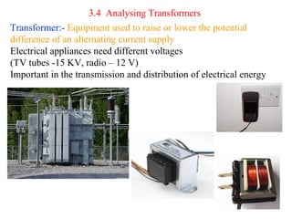
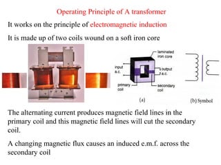
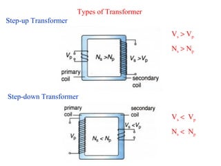
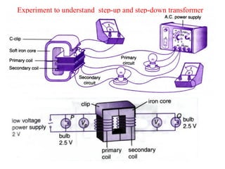
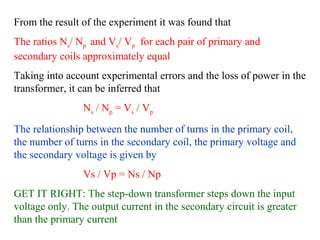
- Transformers work on the principle of electromagnetic induction to change the voltage of an alternating current while keeping the current the same. They have a primary coil connected to a power source and a secondary coil where power is output.
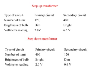
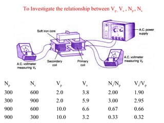
- The ratio of turns between the primary and secondary coils determines whether it is a step-up or step-down transformer. A step-down transformer decreases voltage and increases current while a step-up does the opposite.
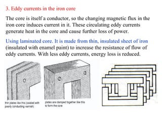
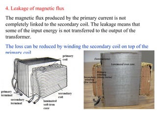
- Efficiency is affected by resistance in coils, hysteresis losses in the core, eddy currents, and magnetic flux leakage. Laminated cores and thicker wire can improve efficiency.
![Efficiency of a Transformer
The efficiency is defined as
E= [Output power/Input power ] x 100%
E= [ VsIs / Vp Ip ] x 100%.
In the process of transfer electrical energy from one circuit to
another a faction of it is lost as heat energy
Efficiency of transformer is normally less than 100%
Ideal Transformer
No energy loss, all the energy supplied to the primary coil will be
transferred to the secondary coil
Has efficiency of 100%
Output power = Input power
VsIs = Vp Ip or Vs / Vp = Ip / Is](https://image.slidesharecdn.com/3-140623194331-phpapp02/85/3-4-analysing-transformer-12-320.jpg)

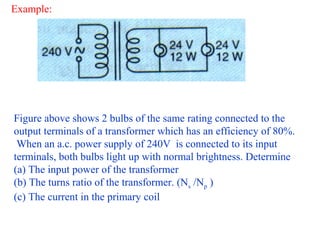
![Answer:
(a) Efficiency= [Output power / Input power ] x 100%
80% = [24/ Input power ]x 100%
Input power = 100/80 x 24= 30 W
( Total output power = V I =24 (I1+I2)
= 24(12/24+12/24)
=24x1=24W
OR total output power is= 12W+12W=24 W
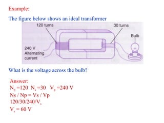
(b) Vs /Vp =Ns /Np
Ns/Np =24/240
=1/10
(c)P = VI
I = P/V =30/240 = 1/8 A](https://image.slidesharecdn.com/3-140623194331-phpapp02/85/3-4-analysing-transformer-15-320.jpg)
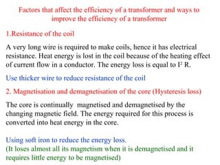
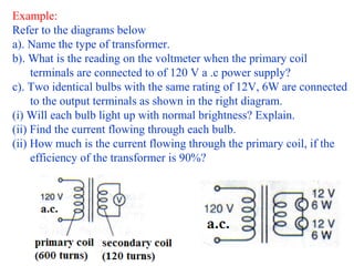
![Answer:
a). Step-down transformer, because Ns < Np
b). Vs /Vp =Ns /Np Vs =Ns/Np x Vp
=120/600 x120 =24 V
c). i) Yes, each bulb will light up with normal brightness, because
the potential difference across each bulb is 12 V.
ii). From P = VI , hence 6 = 12 x Is
Is = 0.5A
iii). Efficiency= [ VsIs / Vp Ip ] x 100%
90% = Vs Is/VpIp x 100%
Ip = [24 x0.5/120 ]x 100/90
=0.111 A](https://image.slidesharecdn.com/3-140623194331-phpapp02/85/3-4-analysing-transformer-20-320.jpg)