Download as PDF, PPTX
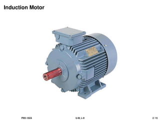
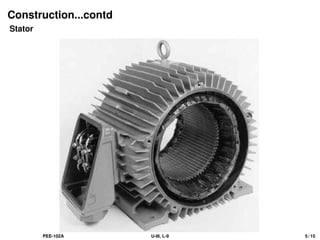
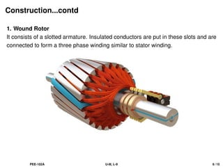
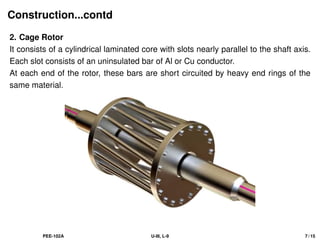
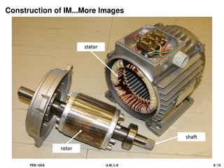
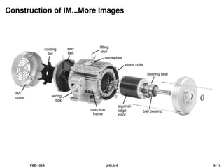
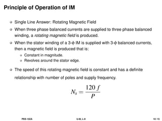
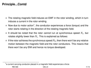

The document provides an overview of three-phase induction motors, highlighting their construction, principles of operation, and characteristics such as high starting torque and speed control. It details the motor's components, including the stator and rotor, and discusses the principle of the rotating magnetic field that induces current in the rotor, resulting in motor action. Additionally, it includes numerical examples illustrating the calculation of synchronous speed, slip, and rotor frequency.


![[Deck] What's New in Spark-Iceberg Integration via DSV2.pptx](https://cdn.slidesharecdn.com/ss_thumbnails/deckwhatsnewinspark-icebergintegrationviadsv2-260210005337-25955b12-thumbnail.jpg?width=640&height=640&fit=bounds)


