Downloaded 175 times
![Design, selection and operation of distribution transformers Stefan Fassbinder Deutsches Kupferinstitut Am Bonneshof 5 D-40474 Düsseldorf Tel.: +49 211 4796-323 Fax: +49 211 4796-310 [email_address] www.kupferinstitut.de deutsch English](https://image.slidesharecdn.com/transformers-1226589251168602-9/85/Transformers-1-320.jpg)


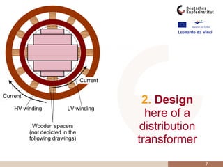

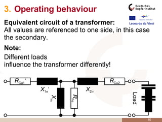


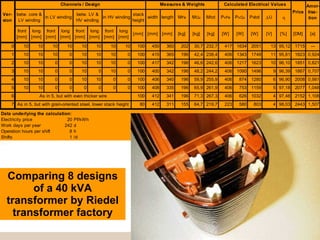


This document provides an overview of distribution transformers including their design, selection, operation, and efficiency. It discusses the need for large power stations and transformers to achieve economies of scale. It also covers transformer design components, equivalent circuits, vector groups, parallel operation, effects of nonlinear loads, and improvements in efficiency over time through better magnetic steel.