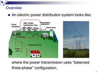
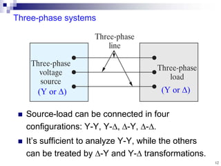
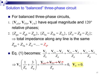
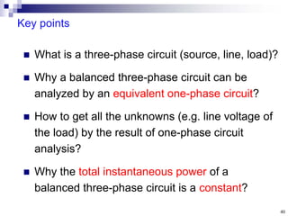
1) A three-phase power distribution system uses a balanced three-phase configuration to transmit power from generators to loads.
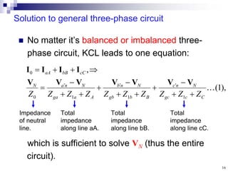
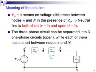
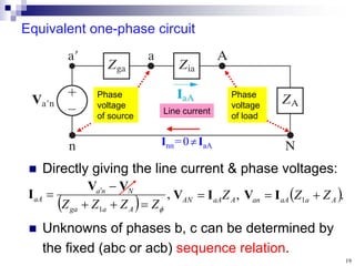
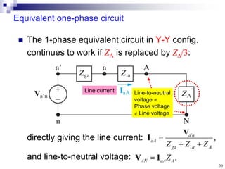
2) A balanced three-phase circuit can be analyzed as an equivalent single-phase circuit. This allows determining the unknown voltages and currents by solving for a single phase.
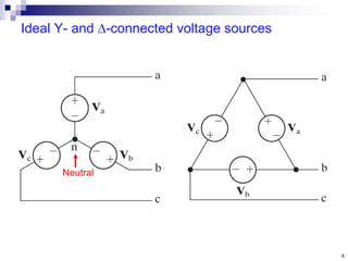
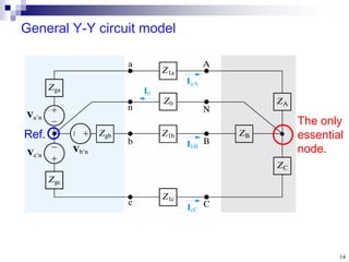
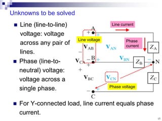
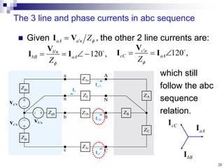
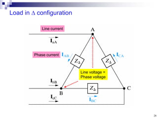
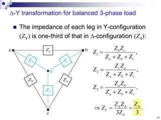
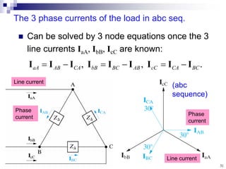
3) For a balanced Y-Y connected three-phase circuit, the line currents are equal and differ in phase by 120 degrees, while the line voltages are √3 times the phase voltages and differ in phase by 30 degrees.