Download as PDF, PPTX
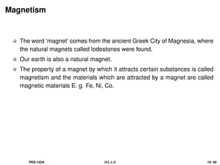
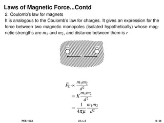
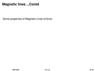
![Solution...Contd
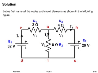
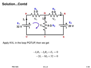
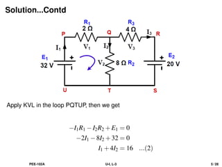
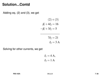
Apply KVL in the loop QRSTQ, then we get
−I3R3 −20+I2R2 = 0
−4I3 +8I2 −20 = 0
−4(I1 −I2)+8I2 = 20 [from Eq.(1)]
PEE-102A U-I, L-3 6 / 28](https://image.slidesharecdn.com/pee102au1l-3-new-210829181815/85/PEE-102A_L-3-11-320.jpg)
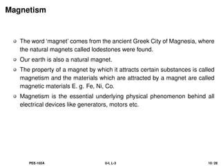
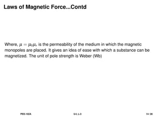
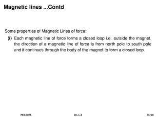
![Solution...Contd
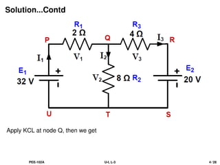
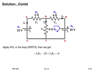
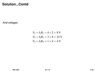
Apply KVL in the loop QRSTQ, then we get
−I3R3 −20+I2R2 = 0
−4I3 +8I2 −20 = 0
−4(I1 −I2)+8I2 = 20 [from Eq.(1)]
−4I1 +12I2 = 20
PEE-102A U-I, L-3 6 / 28](https://image.slidesharecdn.com/pee102au1l-3-new-210829181815/85/PEE-102A_L-3-12-320.jpg)
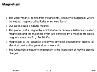
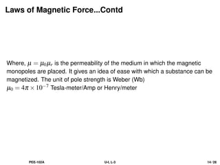
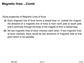
![Solution...Contd
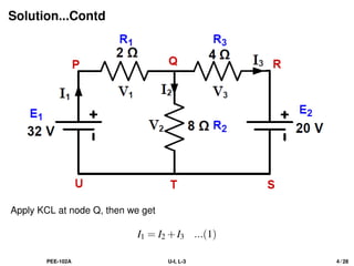
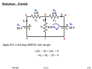
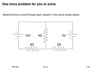
Apply KVL in the loop QRSTQ, then we get
−I3R3 −20+I2R2 = 0
−4I3 +8I2 −20 = 0
−4(I1 −I2)+8I2 = 20 [from Eq.(1)]
−4I1 +12I2 = 20
3I2 −I1 = 5 ...(3)
PEE-102A U-I, L-3 6 / 28](https://image.slidesharecdn.com/pee102au1l-3-new-210829181815/85/PEE-102A_L-3-13-320.jpg)


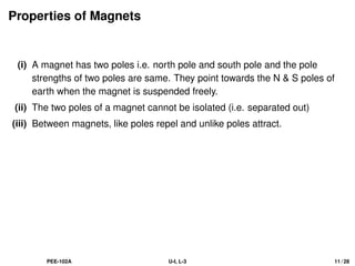

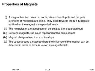
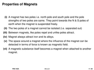
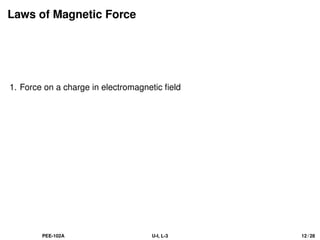
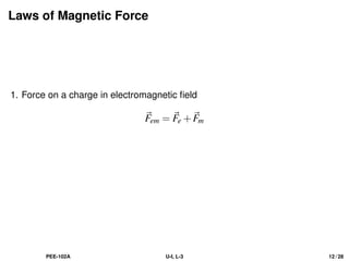
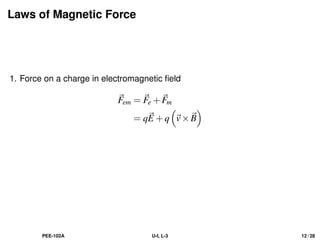
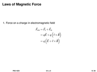
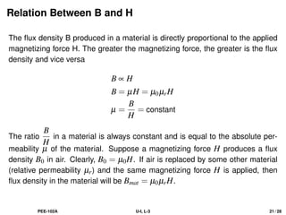
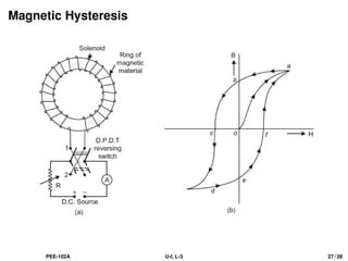
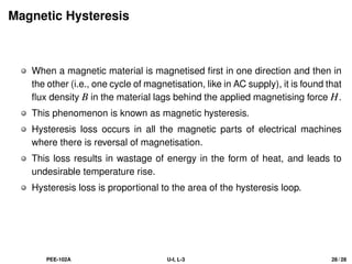

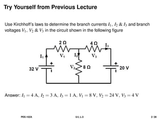
The document provides a comprehensive overview of electrical engineering concepts, specifically focusing on Kirchhoff's laws applied to determine branch currents and voltages in electrical circuits. It also delves into fundamental principles of magnetism, including properties of magnets, laws of magnetic force, and the relationships between magnetic field strength, flux density, and permeability. Key equations and definitions related to these concepts are discussed throughout.