Download as PDF, PPTX

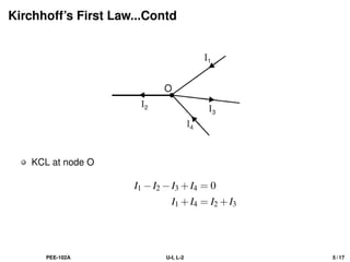
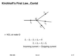
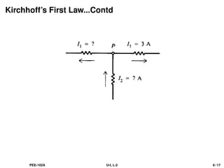
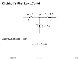
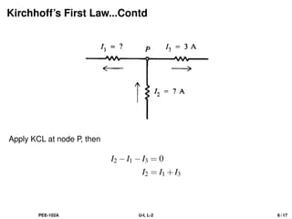
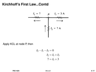
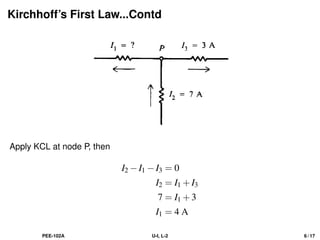
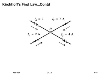
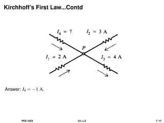
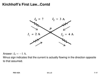
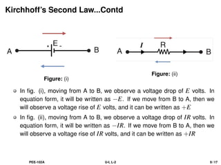
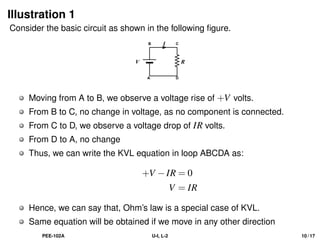
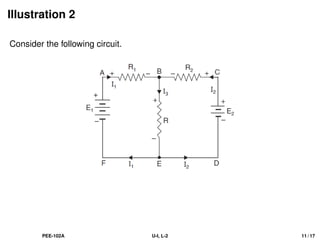
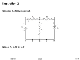
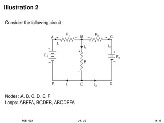
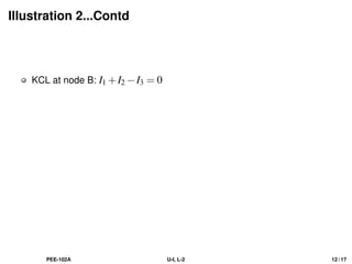
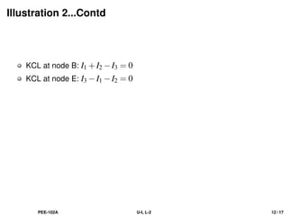
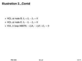
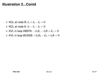
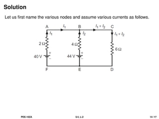
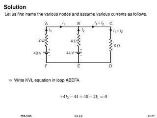
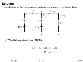
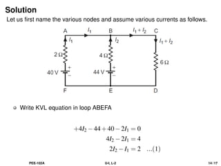
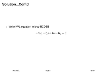
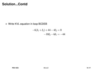
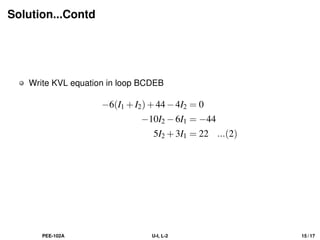
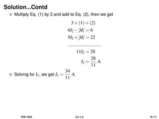
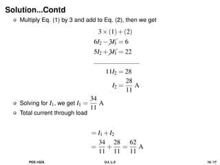
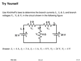

The document discusses Kirchhoff's laws, including the current law (KCL) and the voltage law (KVL), which are based on the conservation of charge and energy, respectively. It provides mathematical formulations of these laws, illustrations of their application in circuit analysis, and examples to calculate currents and voltages in given circuits. Additionally, it emphasizes the significance of these laws in understanding electrical circuits and solving related problems.