Download to read offline
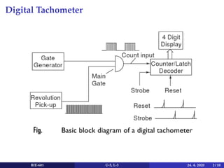
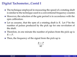
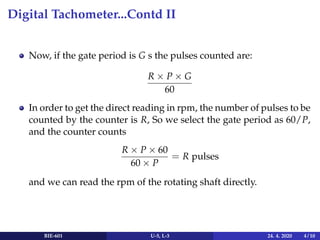
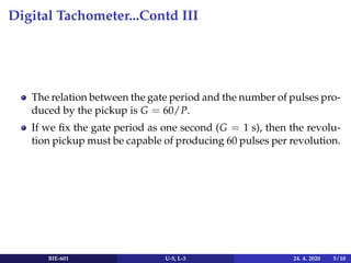
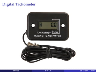
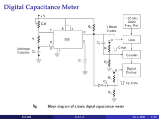

The document discusses digital instruments, focusing on the digital tachometer and digital capacitance meter. It explains the measurement techniques for rotary shaft speed using a conventional frequency counter and characterizes capacitance measurement in RC circuits with a 555 timer. Key concepts include the relationship between pulse frequency, gate period, and direct RPM reading, as well as methods for measuring capacitance directly in microfarads or nanofarads.


