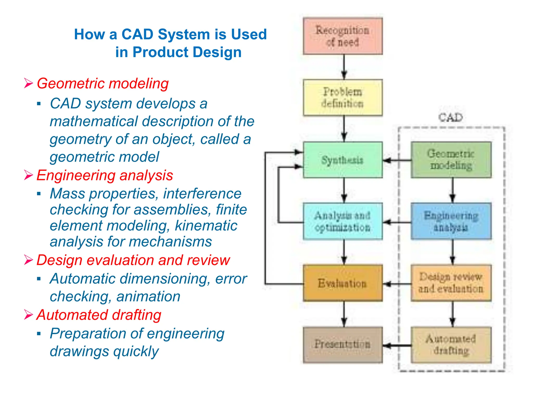
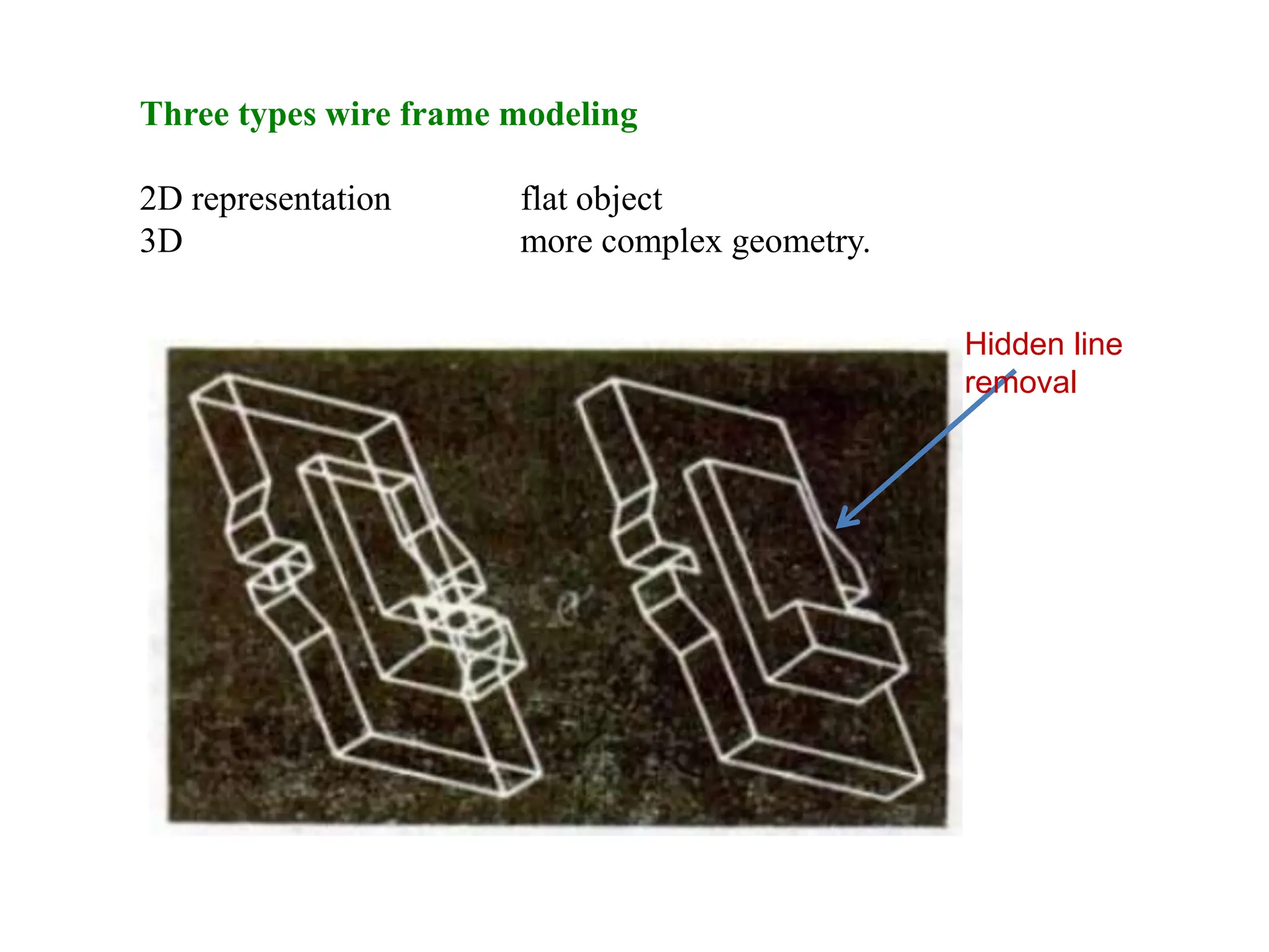
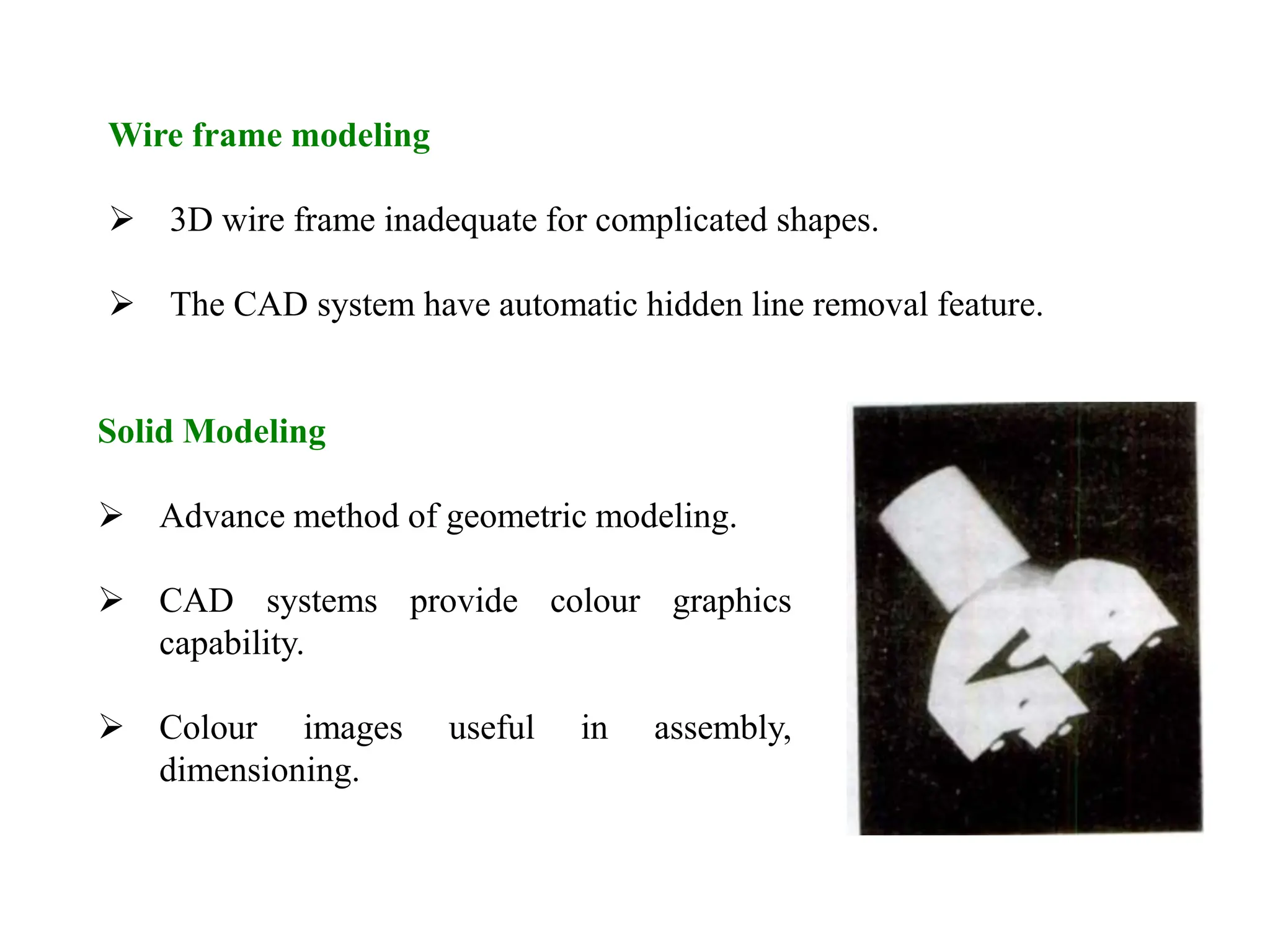
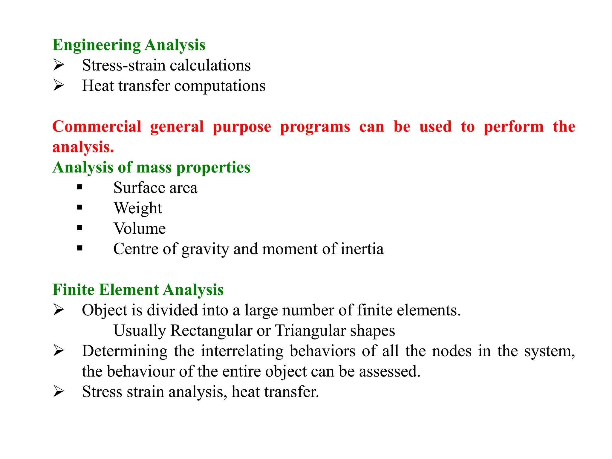
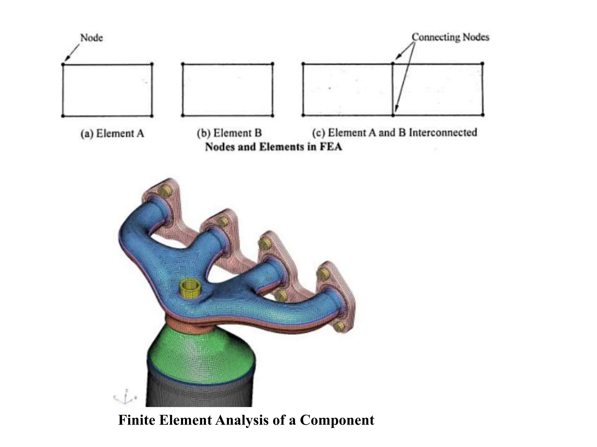
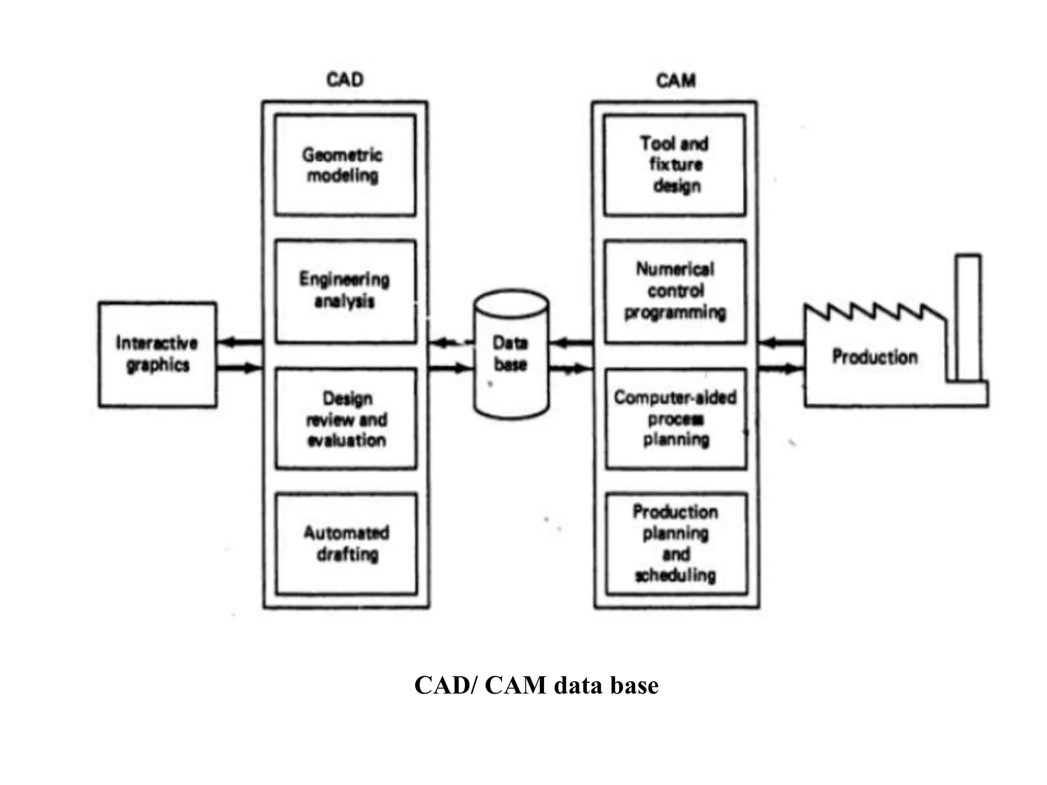
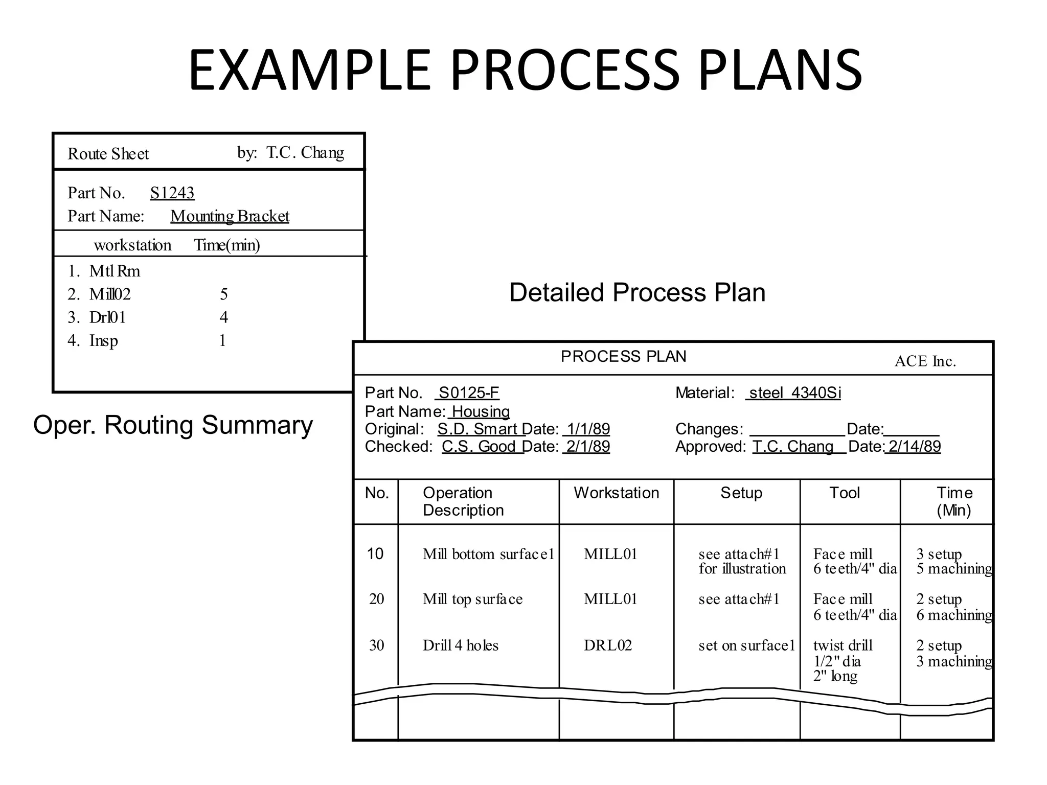
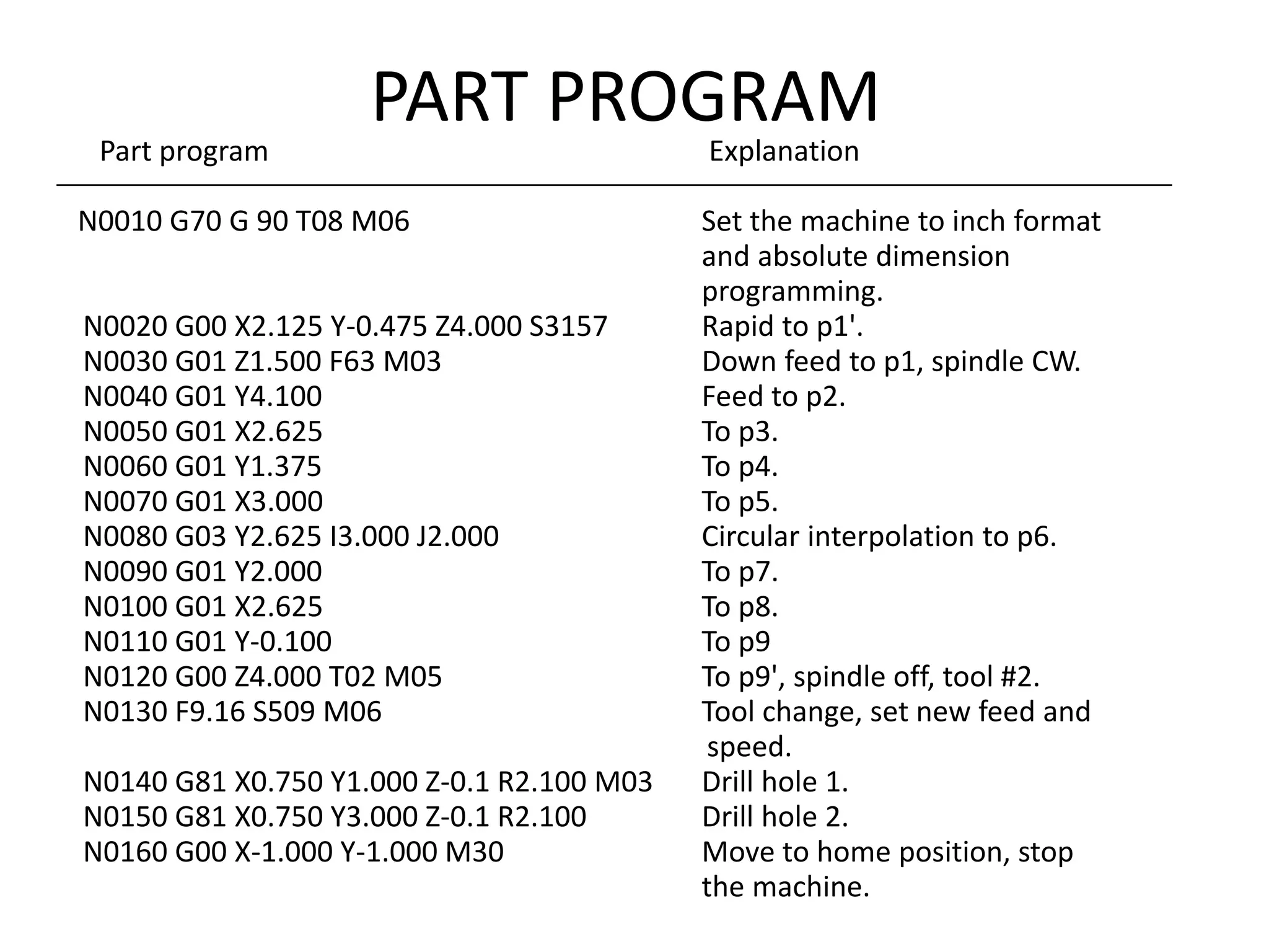
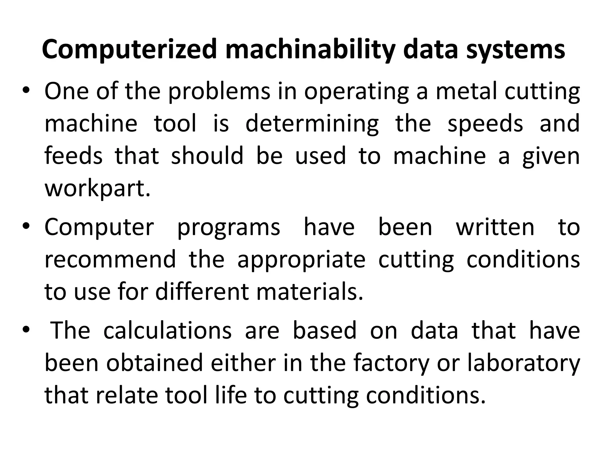
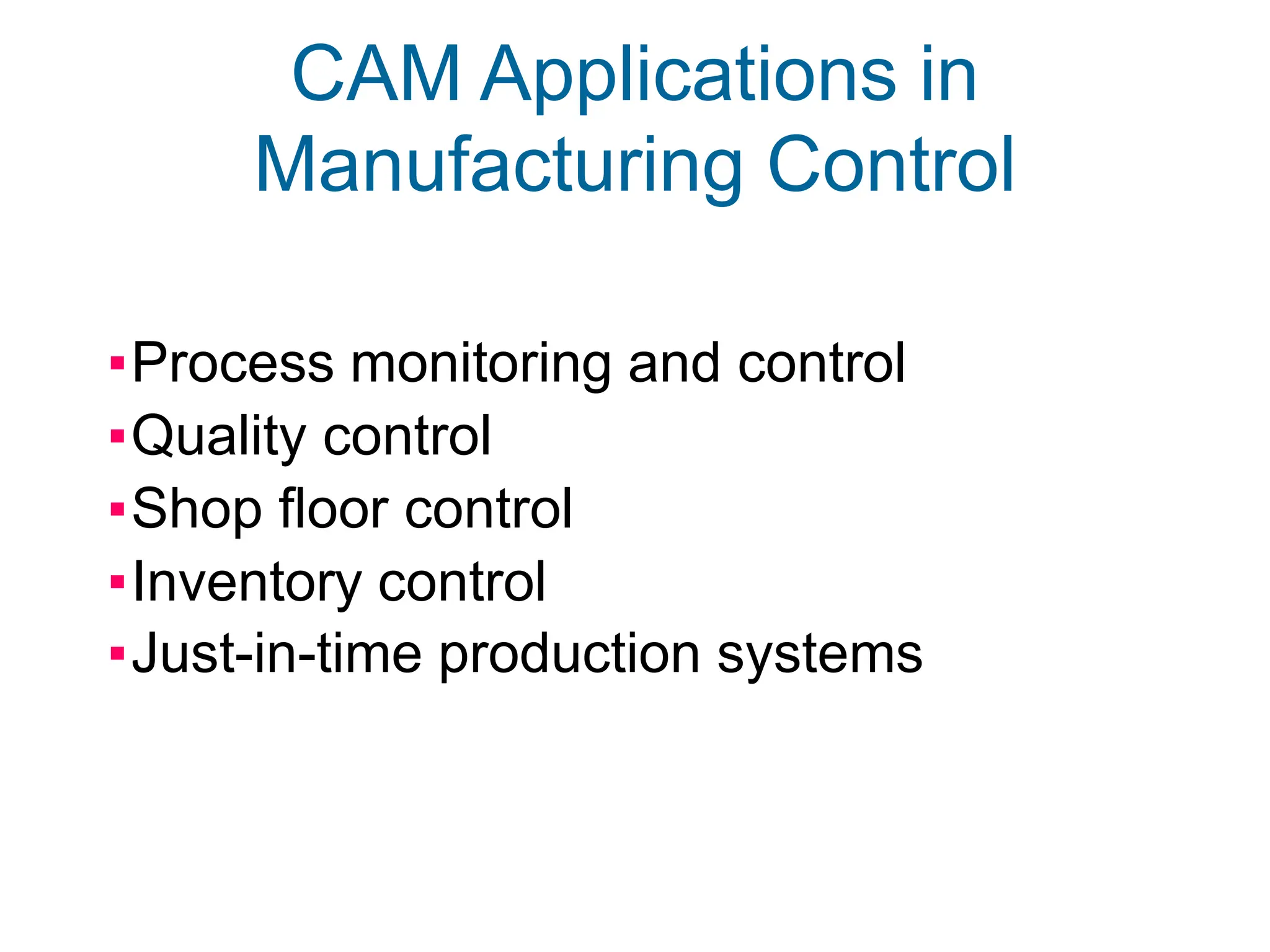
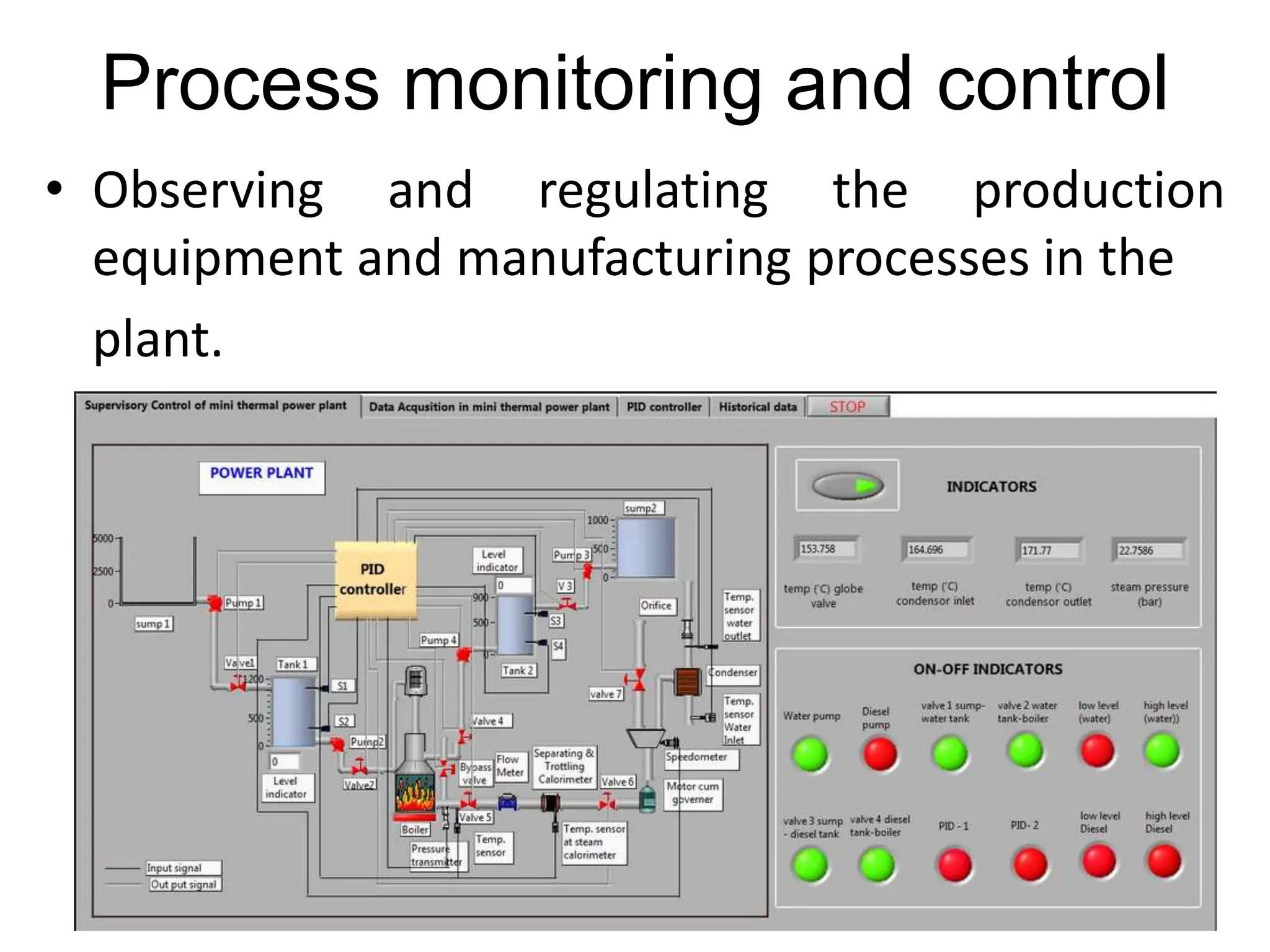
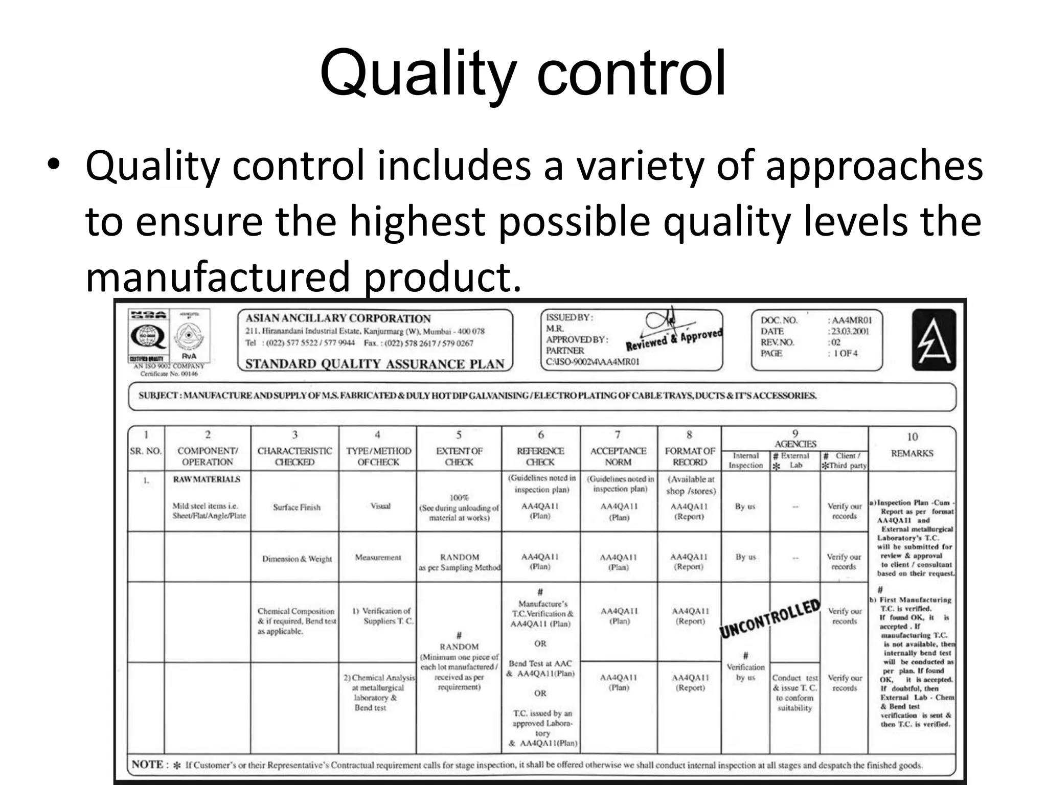
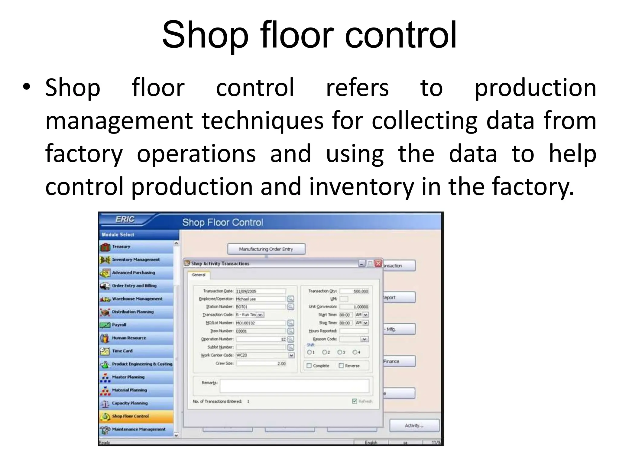
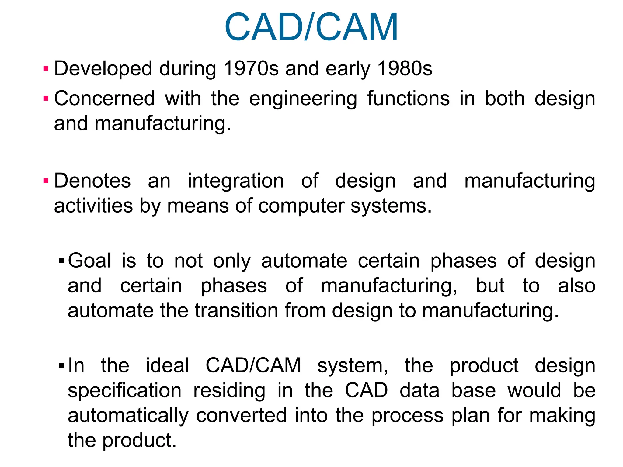
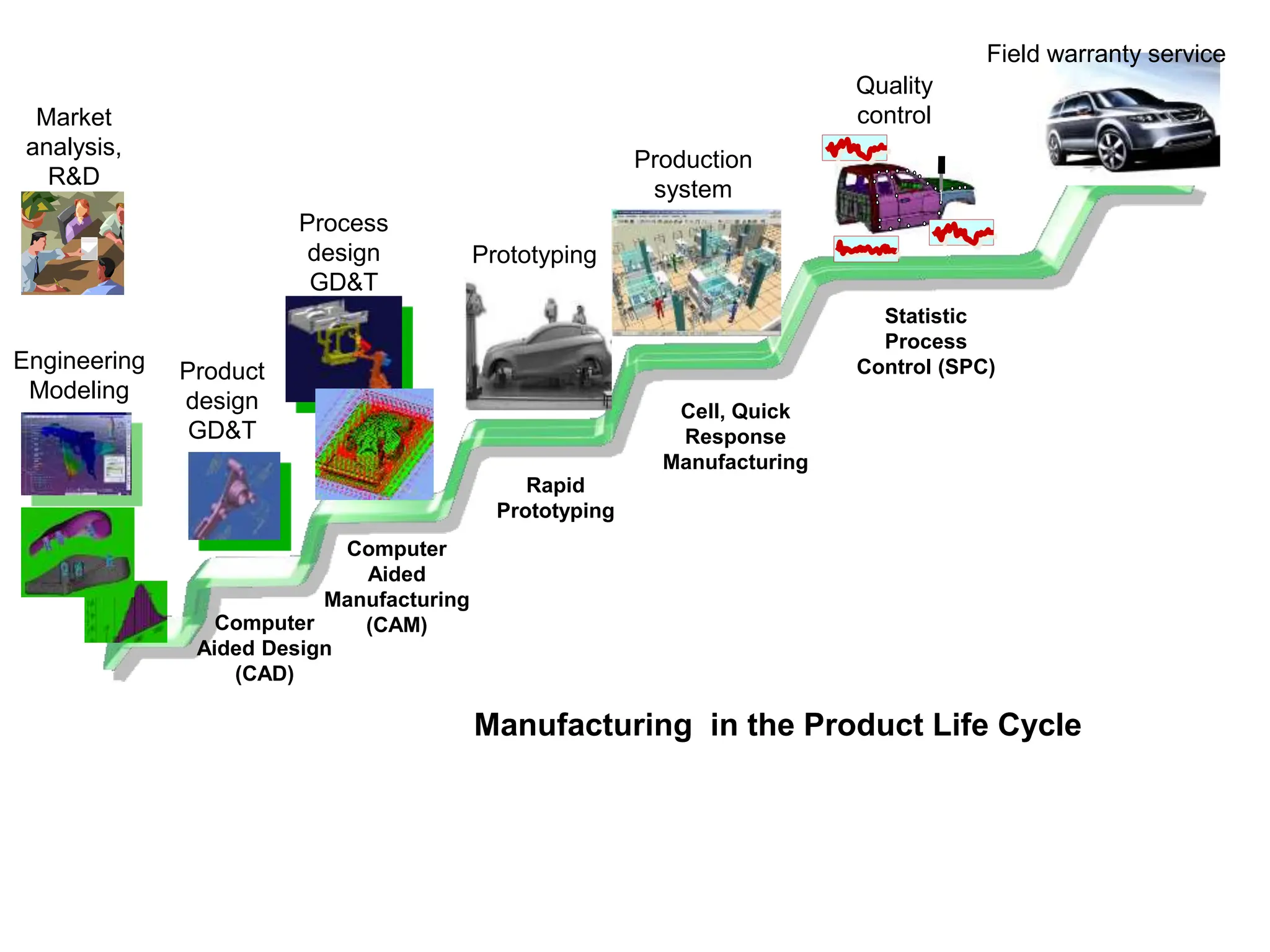
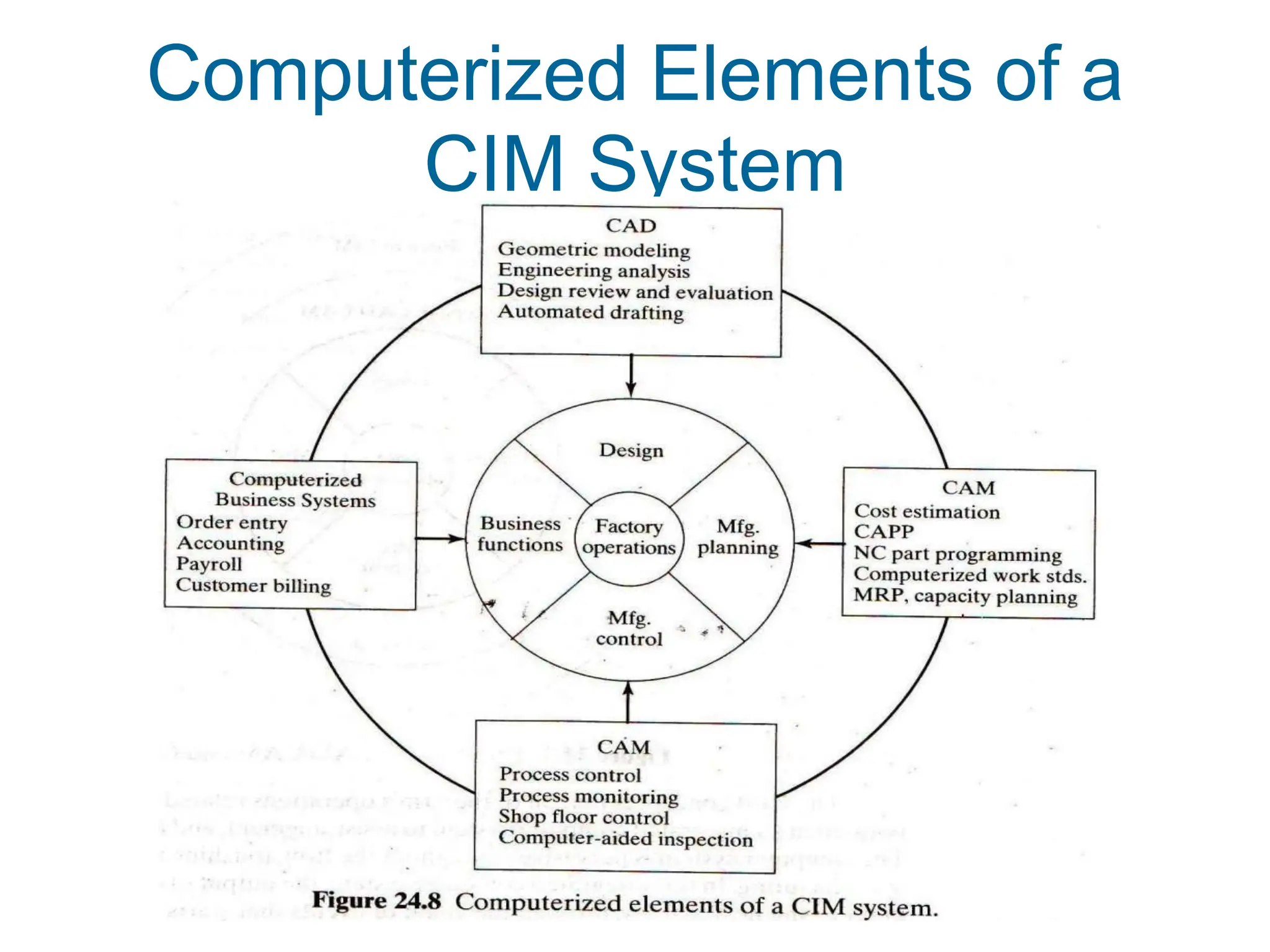
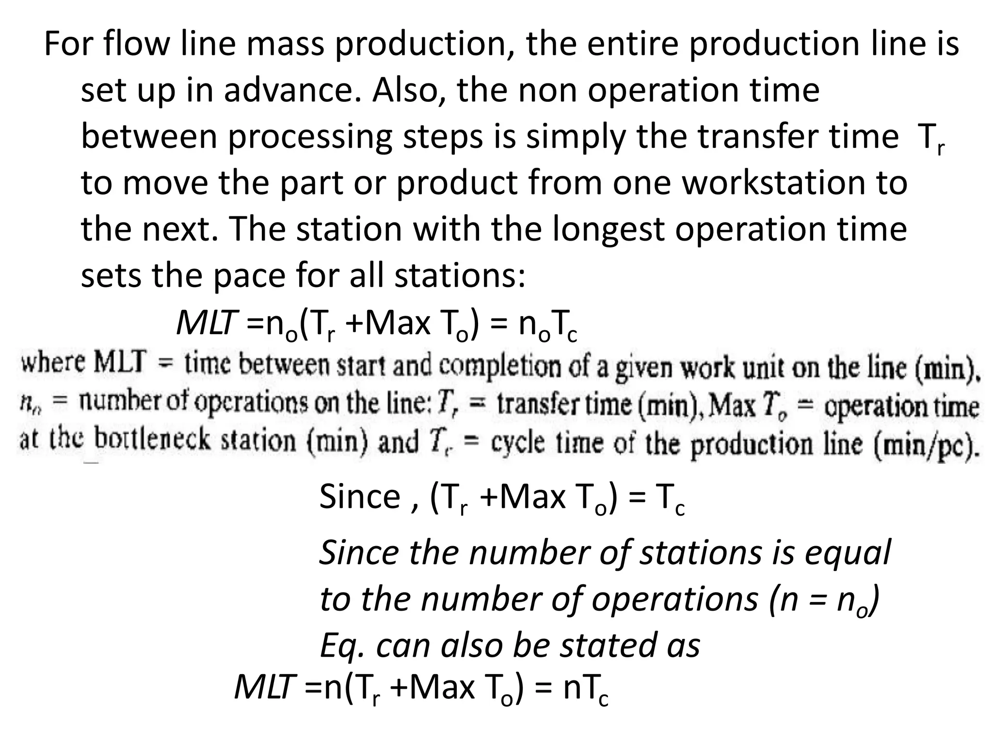
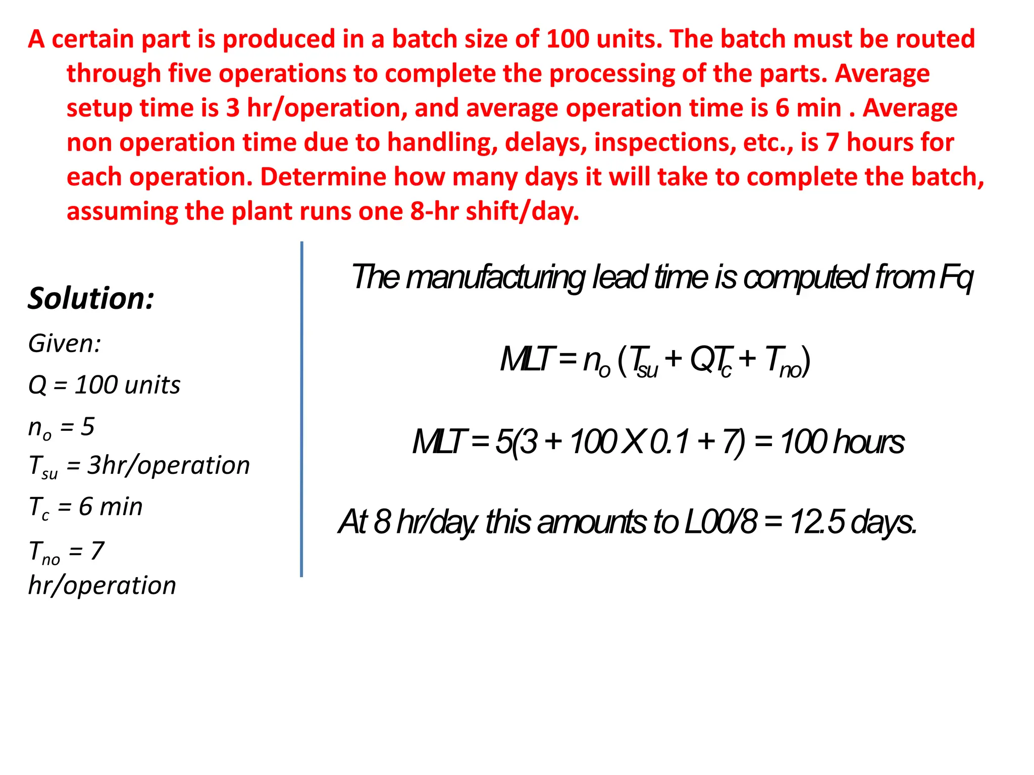
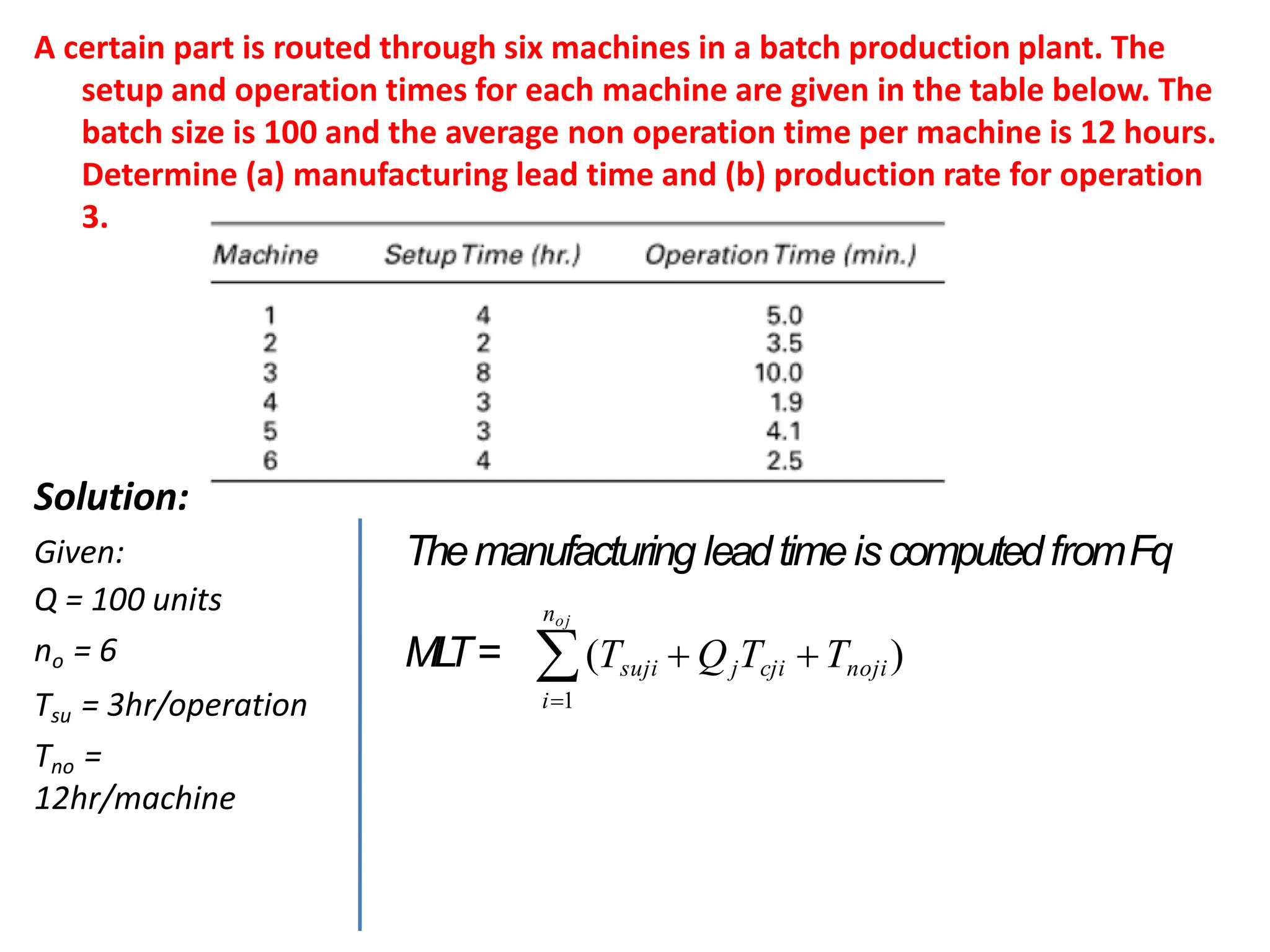
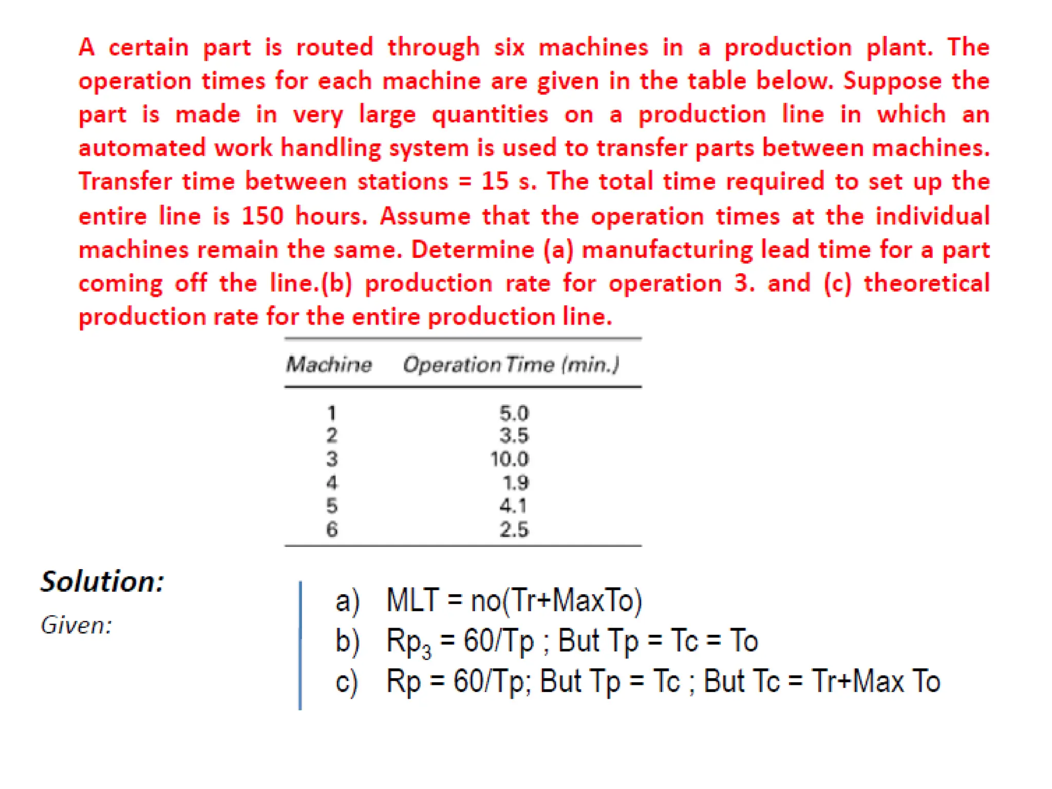
Brief introduction to CAD and CAM – Manufacturing
Planning, Manufacturing control- Introduction to
CAD/CAM – Concurrent Engineering-CIM concepts –
Computerised elements of CIM system –Types of
production - Manufacturing models and Metrics –
Mathematical models of Production Performance –
Simple problems – Manufacturing Control – Simple
Problems – Basic Elements of an Automated system –
Levels of Automation – Lean Production and Just-In-Time
Production.
UNIT
1
Manufacturing Support Systems in the
Production System
Manufacturing Support Systems
The procedures and systems used by a firm to manage its
production operations and solve the technical and logistics
problems associated with:
Designing the products,
Planning the processes,
Ordering materials,
Controlling work-in-process as it moves through the plant, and
Delivering quality products to customers
Design Process
 Design is an original solution
to a problem.
 Design process is the pattern of
activities that is followed by
the designer in arriving at the
solution of a technological
problem.
 Models of the design process
 Shigley and Pahl
 Beitz
 Ohsuga
 Earle
The Design Process
The general process of design is
characterized as an iterative process
consisting of six phases:
1.Recognition of need - someone recognizes
the need that can be satisfied by a new
design,
2.Problem definition - specification of the
item,
3.Synthesis - creation and conceptualization,
4.Analysis and optimization - the concept is
analyzed and redesigned,
5.Evaluation - compare design against
original specification,
6.Presentation - documenting the design
(e.g., drawings).
1. Recognition of need:
It involves the realization by someone that a problem exists for which
some feasible solution is to be found.
Cont..
 Historical Information
 Collected from the literature,
marketing surveys.
 This should be able to answer
questions like
 The current technology
 Existing solutions
 General solutions
 Specify general solution, which will be broad and would not
contain too many details.
 This can be done by resorting to past designs, engineering
standards, technical reports, handbooks, patterns.
 This helps in its further evaluation and refinement at a later
stage.
2. Definition of problem
 It involves a thorough specification of the item to be designed.
 The specification include functional and physical characteristics,
cost, quality, performance, etc.
3. Synthesis
 During this phase various preliminary ideas are developed
through research of similar products or designs in use.
 Requirement Specification
 Clear definition of the requirements is specified.
 This helps in understanding the product from the current practices and
manufacturing resources of the plant.
 Market forces
 Consider the various market forces that will affect the product in one
way or the other.
4. Analysis and optimization:
 The preliminary designs are subjected to the appropriate analysis to
determine their suitability for the specified design constraints.
 If these designs fail to satisfy the constraints, they are then
redesigned or modified on the basis of the feedback from the
analysis.
5. Evaluation:
 The evaluation of the design against the specifications established
during the problem definition phase is then carried out.
 This often requires the fabrication and testing of a prototype model
to evaluate operating performance quality, reliability, etc.
6. Presentation:
 It is the final phase, which includes documentation of the design
through drawings, material specifications, assembly lists and so on.
Shigley- Design Process
 Shigley model involves six basic steps:
Computer Aided Design (CAD)
 CAD is defined as the use of computer systems to assist in the
creation
modification
analysis or optimization of a design.
 The computer system consist of the hardware and software to perform
the specialized design functions.
 The CAD hardware includes
Workstations (Graphic display terminal, CPU)
Keyboards, printers, plotters etc.,
 The CAD software consists of
Computer programs to facilitate the engineering functions
Examples - Stress strain analysis of components
Heat transfer calculations
Numerical control part programming
Reason for implementing CAD
 To increase the productivity of the designer
 Reduces the time required to synthesize, analyze and document
the design.
 To improve the quality of design
 Thorough engineering analysis within a short time.
 Design errors are also reduced.
 To improve communications through documentation:
 Better Engineering drawings
 More standardization in the drawings
 Better documentation of the design
 Fewer drawing errors.
 To create a database for manufacturing:
 Geometry and dimension of components
 Bill of materials
 Used in CNC programming, programming of robots.
 To promote design standardization - use of design rules to limit the number
of hole sizes, fasteners, etc.
 Engineering design has traditionally been accomplished on drawing
boards.
 The process is iterative and time consuming.
 Now computers used in the design process in CAD.
 The design tasks are performed by a CAD system rather than a
single designer working over a drawing board.
Application of Computers in Design Process
How a CAD System is Used
in Product Design
Geometric modeling
▪ CAD system develops a
mathematical description of the
geometry of an object, called a
geometric model
Engineering analysis
▪ Mass properties, interference
checking for assemblies, finite
element modeling, kinematic
analysis for mechanisms
Design evaluation and review
▪ Automatic dimensioning, error
checking, animation
Automated drafting
▪ Preparation of engineering
drawings quickly
Various Design Tasks by CAD
1. Geometric Modeling
2. Engineering Analysis
3. Design Review and Evaluation
4. Automated Drafting
Geometric modeling
 It deals with the mathematical description of the geometry of an
object.
 Using the description the image is displayed and manipulated on a
graphics terminal.
 Softwares are used for provide the geometric modeling.
Three types of commands in Geometric modeling
Basic Geometric elements generates from:
 Points, Lines, Circles.
 Scaling, Rotation, transformations.
 Assembly to join various elements.
Different methods of Representing the object in Geometric
modeling
 Wire Frame Modeling
Displayed by interconnected lines.
 Solid Modeling
Three types wire frame modeling
2D representation flat object
3D more complex geometry.
Hidden line
removal
Wire frame modeling
 3D wire frame inadequate for complicated shapes.
 The CAD system have automatic hidden line removal feature.
Solid Modeling
 Advance method of geometric modeling.
 CAD systems provide colour graphics
capability.
 Colour images useful in assembly,
dimensioning.
Engineering Analysis
 Stress-strain calculations
 Heat transfer computations
Commercial general purpose programs can be used to perform the
analysis.
Analysis of mass properties
 Surface area
 Weight
 Volume
 Centre of gravity and moment of inertia
Finite Element Analysis
 Object is divided into a large number of finite elements.
Usually Rectangular or Triangular shapes
 Determining the interrelating behaviors of all the nodes in the system,
the behaviour of the entire object can be assessed.
 Stress strain analysis, heat transfer.
Finite Element Analysis of a Component
Design Review and Evaluation
 The designer can check the accuracy of the design to reduce the
dimensioning errors.
 The designer can zoom in on part design details for close scrutiny.
 Checking the assembly of the components.
 Kinematics-Animate the motion of components and linkages.
Automated Drafting
 Creation of hardcopy engineering drawings directly from CAD data base.
 It increases productivity five times over manual drafting.
 Automatic dimensioning, crosshatched areas, scaling of the drawing
 Sectional views and enlarged views of particular part details.
 Rotating the part to view the image
Oblique Isometric Perspective
Engineering Drawing with four views
Creating the Manufacturing Data Base
 CAD system develops the data base needed to manufacture the
product.
 In conventional manufacturing
Engineering drawing prepared by design draftsmen and used by
manufacturing engineer to develop the process plan.
 In integrated CAD/CAM system
Direct link established between product design and
manufacturing.
 Manufacturing data base is an integrated CAD/CAM data base.
 It includes all the data on the product generated during design
Geometry data, Bill of materials, Part lists, Material
specifications and additional data required for manufacturing.
CAD/ CAM data base
Benefits of computer aided design
1. Productivity improvement in design
 Complexity of the engineering drawing
 Level of detail required in the drawing
 Degree of repetitiveness in the designed parts
 Degree of symmetry in the parts
2. Shorter lead time
 Speeds up the task of preparing reports and lists (assembly lists)
 Preparation of component drawings takes short time
3. Design Analysis
Conventional:
Designer’s drawing board to design analyst’s queue
CAD system:
Same person can perform analysis.
4. Fewer design errors
 Capability for avoiding design, drafting and documentation
errors.
 Bill of materials are eliminated.
5. Greater accuracy in design calculations
 Dimensional control.
 Change in a single part, effecting the change on all drawings.
6. Standardization of design, drafting and documentation procedure
 The single data base and operating system is common to all
workstation in the CAD system.
 System provides a natural standard for design.
7. Drawings are more understandable
 Creating and maintaining isometrics and oblique drawings .
Improvement in visualization of images
8. Improved Procedures for engineering changes
 Control and implementation of engineering changes is
significantly improved with CAD.
 Data base can be checked against new information.
 Easy to compare with the current design.
Computer-Aided Manufacturing
• The effective use of computer technology in
manufacturing planning and control
▪ Most closely associated with functions in
manufacturing engineering, such as process
planning and NC part programming
▪ CAM applications can be divided into two broad
categories:
1.Manufacturing planning
2.Manufacturing control
Brief introduction to CAD and CAM – Manufacturing
Planning, Manufacturing control- Introduction to
CAD/CAM – Concurrent Engineering-CIM concepts –
Computerised elements of CIM system –Types of
production - Manufacturing models and Metrics –
Mathematical models of Production Performance –
Simple problems – Manufacturing Control – Simple
Problems – Basic Elements of an Automated system –
Levels of Automation – Lean Production and Just-In-Time
Production.
UNIT
1
CAM Applications in
Manufacturing Planning
▪Computer-aided process planning (CAPP)
▪Computer-assisted NC part programming
▪Computerized machinability data systems
▪Computerized work standards
▪Cost estimating
▪Production and inventory planning
▪Computer-aided assembly line balancing
Computer-aided process planning (CAPP)
• Preparation of route sheet
– List the sequence of operation
– Work centers
– Components details
EXAMPLE PROCESS PLANS
Route Sheet
Part No. S1243
Part Name: Mounting Bracket
1. MtlRm
2. Mill02 5
3. Drl01 4
4. Insp 1
workstation Time(min)
by: T.C. Chang
PROCESS PLAN ACE Inc.
Part No. S0125-F
Part Name: Housing
Original: S.D. Smart Date: 1/1/89
Checked: C.S. Good Date: 2/1/89
Material: steel 4340Si
Changes: Date:
Approved: T.C. Chang Date: 2/14/89
No. Operation
Description
Workstation Setup Tool Time
(Min)
10 Mill bottom surface1 MILL01 see attach#1
for illustration
Face mill
6 teeth/4" dia
3 setup
5 machining
20 Mill top surface MILL01 see attach#1 Face mill
6 teeth/4" dia
2 setup
6 machining
30 Drill 4 holes DRL02 set on surface1 twist drill
1/2"dia
2" long
2 setup
3 machining
Detailed Process Plan
Oper. Routing Summary
Computer-assisted NC part
programming
• For complex part geomentries, computer
assisted part programming represents a much
more efficient method of generating the
control instruction for the machine tool than
the manual part programming
PART PROGRAM
Part program Explanation
N0010 G70 G 90 T08 M06 Set the machine to inch format
and absolute dimension
programming.
N0020 G00 X2.125 Y-0.475 Z4.000 S3157 Rapid to p1'.
N0030 G01 Z1.500 F63 M03 Down feed to p1, spindle CW.
N0040 G01 Y4.100 Feed to p2.
N0050 G01 X2.625 To p3.
N0060 G01 Y1.375 To p4.
N0070 G01 X3.000 To p5.
N0080 G03 Y2.625 I3.000 J2.000 Circular interpolation to p6.
N0090 G01 Y2.000 To p7.
N0100 G01 X2.625 To p8.
N0110 G01 Y-0.100 To p9
N0120 G00 Z4.000 T02 M05 To p9', spindle off, tool #2.
N0130 F9.16 S509 M06 Tool change, set new feed and
speed.
N0140 G81 X0.750 Y1.000 Z-0.1 R2.100 M03 Drill hole 1.
N0150 G81 X0.750 Y3.000 Z-0.1 R2.100 Drill hole 2.
N0160 G00 X-1.000 Y-1.000 M30 Move to home position, stop
the machine.
Computerized machinability data systems
• One of the problems in operating a metal cutting
machine tool is determining the speeds and
feeds that should be used to machine a given
workpart.
• Computer programs have been written to
recommend the appropriate cutting conditions
to use for different materials.
• The calculations are based on data that have
been obtained either in the factory or laboratory
that relate tool life to cutting conditions.
Computerized work standards
• The time study department has the responsibility for
setting time standards on direct labor jobs performed in
the factory.
• Establishing standards by direct time study can be a tedious
and time-consuming task.
• There are several commercially available computer
packages for setting work standards.
• These computer programs 'use standard time data that
have been developed for basic work elements that
comprise any manual task.
• By summing the times for the individual element, required
to perform a new Job, the program calculates the standard
time for the job.
Cost Estimating
• The task of estimating the cost of a new product
has been simplified in most industries by
computerizing several of the key steps required to
prepare the estimate.
• The computer is programmed to apply the
appropriate labor and overhead rates to the
sequence of planned operations for the
components of new products.
• The program then sums the individual component
costs from the engineering bill of materials to
determine the overall product cost.
Production and inventory planning
• Maintenance of inventory records,
• Automatic reordering of stock items when
inventory is depicted.
• Production scheduling,
• Maintaining current priorities for the different
Procuction orders,
• Material Requirements Planning, and
• Capacity Planning.
Computer-aided assembly line balancing
• Finding the best allocation of work elements
among stations on an assembly line is a large and
difficult problem if the line of significant size.
• Computer programs have been developed to assist
in the solution of this problem
Brief introduction to CAD and CAM – Manufacturing
Planning, Manufacturing control- Introduction to
CAD/CAM – Concurrent Engineering-CIM concepts –
Computerised elements of CIM system –Types of
production - Manufacturing models and Metrics –
Mathematical models of Production Performance –
Simple problems – Manufacturing Control – Simple
Problems – Basic Elements of an Automated system –
Levels of Automation – Lean Production and Just-In-Time
Production.
UNIT
1
CAM Applications in
Manufacturing Control
▪Process monitoring and control
▪Quality control
▪Shop floor control
▪Inventory control
▪Just-in-time production systems
Process monitoring and control
• Observing and regulating the production
equipment and manufacturing processes in the
plant.
Quality control
• Quality control includes a variety of approaches
to ensure the highest possible quality levels the
manufactured product.
Shop floor control
• Shop floor control refers to production
management techniques for collecting data from
factory operations and using the data to help
control production and inventory in the factory.
Just-in-time production systems
That is organized to
deliver exactly the
right number of
each component to
downstream
workstations in the
manufacturing
sequence just at the
time when that
component is
needed.
Commercial CAM Software
• I-DEAS (Integrated Design and Engineering Analysis Software)
• CATIA Computer Aided Three Dimensional Interactive
Application www.3ds.com/products/catia/
• PRO-Engineerwww.ptc.com/products/proengineer
• Unigraphics www.plm.automation.siemens.com
• Cimatron www.cimatron.com
• Work-NC http://www.sescoi.com/in/products/worknc/
• Power Mill www.powermill.com
• Hyper Mill http://www.openmind- tech.com
• CAM Works
• Master CAM www.mastercam.com
• Surf-CAM
• NC-Gibbs
• Auto-CAD based CAM programs
Brief introduction to CAD and CAM – Manufacturing
Planning, Manufacturing control- Introduction to
CAD/CAM – Concurrent Engineering-CIM concepts –
Computerised elements of CIM system –Types of
production - Manufacturing models and Metrics –
Mathematical models of Production Performance –
Simple problems – Manufacturing Control – Simple
Problems – Basic Elements of an Automated system –
Levels of Automation – Lean Production and Just-In-Time
Production.
UNIT
1
CAD/CAM
▪ Developed during 1970s and early 1980s
▪ Concerned with the engineering functions in both design
and manufacturing.
▪ Denotes an integration of design and manufacturing
activities by means of computer systems.
▪Goal is to not only automate certain phases of design
and certain phases of manufacturing, but to also
automate the transition from design to manufacturing.
▪In the ideal CAD/CAM system, the product design
specification residing in the CAD data base would be
automatically converted into the process plan for making
the product.
Brief introduction to CAD and CAM – Manufacturing
Planning, Manufacturing control- Introduction to
CAD/CAM – Concurrent Engineering-CIM concepts –
Computerised elements of CIM system –Types of
production - Manufacturing models and Metrics –
Mathematical models of Production Performance –
Simple problems – Manufacturing Control – Simple
Problems – Basic Elements of an Automated system –
Levels of Automation – Lean Production and Just-In-Time
Production.
UNIT
1
Field warranty service
Production
system
Prototyping
Process
design
GD&T
Quality
control
Product
design
GD&T
Engineering
Modeling
Market
analysis,
R&D
Computer
Aided Design
(CAD)
Computer
Aided
Manufacturing
(CAM)
Rapid
Prototyping
Cell, Quick
Response
Manufacturing
Statistic
Process
Control (SPC)
Manufacturing in the Product Life Cycle
Definition of Concurrent Engineering
"Concurrent engineering is a systematic approach to the integrated,
concurrent design of products and their related processes, including
manufacture and support. Typically, concurrent engineering involves the
formation of cross-functional teams, which allows engineers and managers of
different disciplines to work together simultaneously in developing product and
process design. This approach is intended to cause the developers, from the
outset, to consider all elements of the product life cycle from concept through
disposal, including quality, cost, productivity, speed (time to market & response
time), and user requirements (include functional and reliability)."
Align all design to support the goal: Satisfy customer expectation
• Quality,
• Cost
• Productivity,
• Speed (time to market & response time)
• User requirements (include functional and reliability)
Support the goal: Return customer and Profitability- How serious?
•Sony battery recall lost $429 million combined 94% profit shrink
•Ford 3-rd net loss $5.8 billion close 16 plants, 45000 jobs
Concurrent Engineering:
Is a strategy where all the tasks involved in product development
are done in parallel.
Collaboration between all individuals, groups and departments
within a company.
• Customer research
• Designers
• Marketing
• Accounting
• Engineering
Concurrent Engineering
Form Design
Functional
Design
Production
Design
Revising and testing
prototypes
Manufacturing
Specifications
Design
Specifications
Feasibility
Study
Idea
Generation
Suppliers R&D Customers
Marketing
Competitors
Product or Service concept
Performance Specifications
Pilot run and final
tests
Final Design
and process
plans
Product Launch
Preliminary
Design
Commercial
Design Process
Linear Process
Concurrent Engineering
Techniques:
•Benchmarking
•Reverse Engineering
Concurrent Engineering
Low
Nutrition
Good
Taste
Bad Taste
High
Nutrition
Coco Pops
Rice Krispies
Cheerios
Shredded Wheat
Perceptual Mapping
•Compares customers perception of available products
•Identifies gap in market
Concurrent Engineering
Demand for the proposed product?
Cost of developing and producing the product?
Does company have manufacturing capability?
Skilled personnel?
Concurrent Engineering
Form Design: Physical appearance of the product
Functional Design: Performance of the product
Production Design: How to manufacture product
Concurrent Engineering
•Prototype produced
•Adjustments made
•Final specification agreed
Concurrent Engineering
•Manufacturing process commences
•Product is marketed to buying public
Concurrent Engineering
Traditional Process = Linear
Vs
Concurrent Engineering = Team collaboration
Traditional Design and
Production Process
the main problems/difficulties associated with
traditional design and production process:
FOR COMPLEX PRODUCTS:
• Cycle Time Too Long
• Facility Intensive
• Cost High
• Convergence Not Assured
Conventional product design
approach
How dose CE reduce time?
•Why do companies now want to move away from serial product
development process ?
Concurrent engineering of products
Address all issues related to the complete life cycle
of the product at the product design stage - from
initial conceptualization, to disposal/scrap of the
product.
Concurrent engineering
• Has to be supported by top management.
• All product development team members should be dedicated for
the application of this strategy.
• Each phase in product development has to be carefully planned
before actual application.
• New product’s lifecycle has to fit in in the existing product
program lifecycles in a company.
Benefits of Concurrent Engineering
•Reduces time from design concept to market launch by 25% or
more
• Reduces Capital investment by 20% or more
• Supports total quality from the start of production with earlier
•opportunities for continuous improvement
• Simplifies after-sales service
• Increases product life-cycle profitability throughout the supply
system
Assembly in the Context of Product
Development
Brief introduction to CAD and CAM – Manufacturing
Planning, Manufacturing control- Introduction to
CAD/CAM – Concurrent Engineering-CIM concepts –
Computerised elements of CIM system –Types of
production - Manufacturing models and Metrics –
Mathematical models of Production Performance –
Simple problems – Manufacturing Control – Simple
Problems – Basic Elements of an Automated system –
Levels of Automation – Lean Production and Just-In-Time
Production.
UNIT
1
Manufacturing engineers are required to achieve
the following objectives to be competitive in a
global context
– Reduction in inventory
– Lower the cost of the product
– Reduce waste
– Improve quality
– Increase flexibility in manufacturing to achieve
immediate and rapid response to:
• Product & Production changes
• Process & Equipment change
• Change of personnel
The Scope of CAD/CAM and CIM
Computer Integrated
Manufacturing
▪ Includes all of the engineering functions of CAD/CAM,
▪ Also includes the firm's business functions that are
related to manufacturing,
▪ Ideal CIM system applies computer and communications
technology to all of the operational functions and
information processing functions in manufacturing.
▪ From order receipt,
▪ Through design and production,
▪ To product shipment.
Brief introduction to CAD and CAM – Manufacturing
Planning, Manufacturing control- Introduction to
CAD/CAM – Concurrent Engineering-CIM concepts –
Computerised elements of CIM system –Types of
production - Manufacturing models and Metrics –
Mathematical models of Production Performance –
Simple problems – Manufacturing Control – Simple
Problems – Basic Elements of an Automated system –
Levels of Automation – Lean Production and Just-In-Time
Production.
UNIT
1
Computerized Elements of a
CIM System
Benefit from CIM
Integration of technologies brings following benefits:
1. Creation of a truly interactive system that enables
manufacturing functions to communicate easily with
other relevant functional units
2. Accurate data transferability among manufacturing
plant or subcontracting facilities at implant or diverse
locations
3. Faster responses to data-changes for manufacturing
flexibility
4. Increased flexibility towards introduction of new
products
5. Improved accuracy and quality in the manufacturing
process
Benefit from CIM
6. Improved quality of the products.
7. Control of data-flow among various units and
maintenance of user-library for system-wide
data.
8. Reduction of lead times which generates a
competitive advantage.
9. Streamlined manufacturing flow from order to
delivery.
10. Easier training and re-training facilities.
Brief introduction to CAD and CAM – Manufacturing
Planning, Manufacturing control- Introduction to
CAD/CAM – Concurrent Engineering-CIM concepts –
Computerised elements of CIM system –Types of
production - Manufacturing models and Metrics –
Mathematical models of Production Performance –
Simple problems – Manufacturing Control – Simple
Problems – Basic Elements of an Automated system –
Levels of Automation – Lean Production and Just-In-Time
Production.
UNIT
1
Production System
A collection of people, equipment, and procedures
organized to accomplish the manufacturing
operations of a company
Two categories:
• Facilities – the factory and equipment in the facility
and the way the facility is organized (plant layout)
• Manufacturing support systems – the set of
procedures used by a company to manage
production and to solve technical and logistics
problems in ordering materials, moving work
through the factory, and ensuring that products
meet quality standards
T
ypesof ManufacturingSystems
1. Continuous-flow processes. Continuous dedicated
production of large amount of bulk product. Continuous
manufacturing is represented by chemicals, plastics,
petroleum, and food industries.
2. Mass production of discrete products. Dedicated
production of large quantities of one product (with perhaps
limited model variations). Examples include automobiles,
appliances and engine blocks.
3. Batch production. Production of medium lot sizes of the
same product. The lot may be produced once or repeated
periodically. Examples: books, clothing and certain industrial
machinery.
4. Job-shop production. Production of low quantities, often
one of a kind, of specialized products. The products are
often customized and technologically complex.
Examples: prototypes, aircraft, machine tools and other
Production
quantity
Continuous
- flow
production
Mass
production
Batch
production
Job shop
production
Product
variety
Category Automation achievements
Continuous-flow process •Flow process from beginning to end
•Sensors technology available to
measure important process variables
•Use of sophisticated control and optimization
strategies
•Fully computer automated lines
Mass production of discrete products •Automated transfer machines
•Dial indexing machines
•Partially and fully automated assembly lines
•Industrial robots for spot welding, part handling,
machine loading, spray painting, etc.
•Automated material handling systems
•Computer production monitoring
Batch production •Numerical control (NC), direct numerical
control (DNC), computer numerical control
(CNC).
•Adaptive control machining
•Robots for arc welding, parts handling, etc.
•CIM systems.
Job shop production •Numerical control, computer numerical control
Brief introduction to CAD and CAM – Manufacturing
Planning, Manufacturing control- Introduction to
CAD/CAM – Concurrent Engineering-CIM concepts –
Computerised elements of CIM system –Types of
production - Manufacturing models and Metrics –
Mathematical models of Production Performance –
Simple problems – Manufacturing Control – Simple
Problems – Basic Elements of an Automated system –
Levels of Automation – Lean Production and Just-In-Time
Production.
UNIT
1
Production Concepts and
Mathematical Models
• Production rate Rp
• Production capacity PC
• Utilization U
• Availability A
• Manufacturing lead time MLT
• Work-in-progress WIP
Production rate Rp
• Hourly production rate
• Work units completed/Hr
• Cycle time: Time that one work unit spends being
processed or assembled. It is the time between
when one work unit begins processing and next
unit begins.
• Not all time is productive.
• Cycle time consists of i) actual machining
operation time ii) workpart handling time
iii) tool handling time per workpiece
Operation Cycle Time
Typical cycle time for a production operation:
Tc = To + Th + Tth
where
Tc = cycle time, min/pc
To = processing time for the operation, min/pc
Th = handling time (e.g., loading and unloading
the production machine), min/pc and
Tth = tool handling time (e.g., time to change
tools), min/pc
Tool handling time
• Time spent changing tools when worn out
• Time required for changing one tool to the
next.
• Tool indexing time for indexable inserts or for
tools on a turret lathe
• Tool positioning for next pass etc..
– These activities do not occur every cycle
– They must be spread over the number of parts
Production rate for
batch production
Time to process one batch(Q units) = Setup time +
processing time, i.e., Tb = Tsu + QTc
where
Tb = Batch processing time in min
Tsu = Setup time required for one batch in min
Q = Batch quantity, pc
Tc = cycle time per workunit in min/cycle
Tp = Tb / Q ,
whereTp= Avg prod. Time/workunit , min/pc
Rp = 60 / Tb ,
Where Rp = hourly production rate (pc/hr)
Production rate for
mass production
Production rate = cycle rate of the machine
Tb = Tsu + QTc
For mass production, Q = very large
Tp = Tb/Q = (Tsu + QTc ) / Q = Tsu /Q + QTc /Q
Tp = Tsu/Q +Tc
As Q becomes very large, Tsu/Q  0
So, Tp = Tc
WKT, Production rate is reciprocal of production time
Rp = Rc = 60/Tc
Production rate for
flow line mass production
• Production rate = cycle rate of the production line
• Workstations are interdependent in the line
• Impossible to divide total work equally among all
workstations on the line.
• So, one station ends up with the longest
operation time ( Bottle neck station).
• Bottle neck station sets the pace to other
workstation.
• Work units should be moved from one workstation
to next (Tr)
Production rate for
flow line mass production
• Cycle time = transfer time + longest processing time
Tc = Tr + Max To
• Where Max To = operation time at the bottle neck
station i.e., The maximum of operation times for all
stations on the line
• Tr = Transfer time
Rc = 60/Tc
Production capacity
• maximum rate of output that a production
facility (or production line, work center, or
group of work centers) is able to produce under
a given set of assumed operating conditions
• Operating conditions refer to the number of
shifts per day, number of days in the week (or
month) that the plant operates, employment
levels, and so forth.
Production capacity
Let PCw = the production capacity of a given facility under
consideration.
Let the measure of capacity = the number of units produced per
week.
Let n = the number of machines or work centers in the facility.
A work center is a manufacturing system in the plant typically
consisting of one worker and one machine. It might also be one
automated machine with no worker, or multiple workers working
together on a production line.
It is capable of producing at a rate RP unit/hr. Each work center
operates for Hs hr/shift.
Let Sw denote the number of shifts per week.
PCw = n Sw Hs Rp
Production capacity
• If we include the possibility that each work
unit is routed through no operations, with
each operation requiring a new setup on
either the same or a different machine,
• where no = number of operations in the routing
Production Capacity
where no = number of operations in the routing
Plant capacity for facility in which parts are
made in one operation (no = 1):
PCw = n Sw Hs Rp
where PCw = weekly plant capacity, units/wk
Plant capacity for facility in which parts
require multiple operations (no > 1):
Production Capacity
Equation indicates the operating parameters that
affect plant capacity.
Changes that can be made to increase or decrease
plant capacity over the short term are:
1.Change the number of shifts per week (S). For
example, Saturday shifts might be authorized to
temporarily increase capacity.
2.Change the number of hours worked per shift
(H). For example, overtime on each regular shift
might be authorized to increase capacity.
Utilization
• Utilization refers to the amount of output of a
production facility relative to its capacity. Expressing
U=Q/PC
Where U = utilization of the facility,
Q = actual quantity produced by the facility during a given time
period (i.e., pc/wk), and
PC = production capacity for the same period (pc/wk).
It is often defined as the proportion of time that the
facility is operating relative to the time available under
the definition of capacity.
Utilization is usually expressed as a percentage.
Availability
• Availability is defined using two other
reliability terms, mean time between failure
(MTBF) and mean time to repair (MTTR).
• The MTBF indicates the average length of time
the piece of equipment runs between
breakdowns.
• The MTTR indicates the average time required to
service the equipment and put it back into
operation when a breakdown occurs.
Availability
Availability is defined as follows:
Availability: A =
where MTBF = mean time between failures, and
MTTR = mean time to repair
Availability is typically expressed as a percentage
MTBF
MTBF  MTTR
-----------10
Availability -
MTBF and MTTR Defined
1) A production machine operates at 2 shifts/day and 5 days a week at full
capacity. Its production rate is 20 unit/hr. During a certain week, the
machine produced 1000 parts and was idle in the remaining time, (a)
Determine the production capacity of the machine, (b) What was the
utilization of the machine during the week under consideration?
if the availability of the machine is 90%, and the utilization of the machines
is 80%. Compute the expected plant output.
Solution:
(a)The capacity of the machine can be determined using the
assumed 80-hr week as follows:
PC = 80(20) = 1600 unit/wk
(b)Utilization can be determined as the ratio of the number of
parts made by the machine relative to its capacity.
U = 1000/1600 = 0.625 (62.5%)
(c) U=Q/PC or
Q= UxPCxA or UAxnSHRp
2) The mean time between failures for a certain production machine is 250 hours,
and the mean time to repair is 6 hours. Determine the availability of the
machine.
Availability: A =
3) One million units of a certain product are to be manufactured annually on
dedicated production machines that run 24 hours per day. 5 days per week, 50
weeks per year, (a) If the cycle time of a machine to produce one part is 1.0
minute, how many of the dedicated machines will be required to keep up with
demand? Assume that availability, utilization, and worker efficiency = 100%, and
that no setup time will be lost, (b) Solve part (a) except that availability = 0.90.
Solution: Tc= 1 min
Tb = Tsu+QTc = 0+QTc
Tp= Tb/Q = Tc
Rp=60/Tp = 60 Parts/Hr
n= PC/SHRp
= 1000000/(50x5x24x60)
= 2.77 = 3 machines
MTBF
MTBF  MTTR
Let Tc = the operation cycle time at a given machine or workstation,
Tno = the non operation time associated with the same machine.
no = the number of separate operations through which the work unit
must be routed
Tsu = Setup time required to prepare each production machine for
the particular product. If we assume batch production, then there
are Q work units in the batch.,
Given these terms, we can define manufacturing lead time as
MLTj =
where
MLTj = manufacturing lead time for part or product j (min).
Tsuji = setup time for operation i (min) for the product j,
Qj = quantity of part or product in the batch (pc),
Tcji = operation cycle time for operation i (min/pc),
Tnoji = nonoperation time associated with operation i (min), and
i1
noj
(Tsuji  QjTcji Tnoji)
i in4
d
/3/i2
c
01
a
4tes the operation se
Ha
q
ree
u
sh
e
an
NG
c,e
Dei
pn
t oft
Ae
h
ro
e
Enp
ggr
, D
o
Sc
CE
e
, B
slo
sre
ing; i = I, 2,... noj
Tno= Non Operating Time
• For a job shop in which the batch size is one (Q = 1),
MLT=no(Tsu+TC+Tno)
For mass production, the Q term in Eq. is very large and
dominates the other terms.
In the case of quantity type mass production in which a
large number of units are made on a single machine (no=1).
The MLT simply becomes the operation cycle time for the
machine after the setup has been completed and
production begins.
MLT = QxTc
For flow line mass production, the entire production line is
set up in advance. Also, the non operation time
between processing steps is simply the transfer time Tr
to move the part or product from one workstation to
the next. The station with the longest operation time
sets the pace for all stations:
MLT =no(Tr +Max To) = noTc
Since , (Tr +Max To) = Tc
Since the number of stations is equal
to the number of operations (n = no)
Eq. can also be stated as
MLT =n(Tr +Max To) = nTc
A certain part is produced in a batch size of 100 units. The batch must be routed
through five operations to complete the processing of the parts. Average
setup time is 3 hr/operation, and average operation time is 6 min . Average
non operation time due to handling, delays, inspections, etc., is 7 hours for
each operation. Determine how many days it will take to complete the batch,
assuming the plant runs one 8-hr shift/day.
Solution:
Given:
Q = 100 units
no = 5
Tsu = 3hr/operation
Tc = 6 min
Tno = 7
hr/operation
Themanufacturing leadtimeiscomputedfromFq
ML
T=no (T
su +QT
c +Tno)
ML
T=5(3+100X0.1+7) =100hours
At8hr/day
. thisamountstoL00/8=12.5days.
A certain part is routed through six machines in a batch production plant. The
setup and operation times for each machine are given in the table below. The
batch size is 100 and the average non operation time per machine is 12 hours.
Determine (a) manufacturing lead time and (b) production rate for operation
3.
Solution:
Given:
Q = 100 units
no = 6
Tsu = 3hr/operation
Tno =
12hr/machine
ML
T=
Themanufacturing leadtimeiscomputedfromFq
noj
(Tsuji  QjTcji Tnoji)
i1
Work-In-Process
Work-in-process (WIP) is the quantity of parts or
products currently located in the factory that
either are being processed or are between
processing operations.
WIP is inventory that is in the state of being
transformed from raw material to finished
product.
Work-In-Process
An approximate measure of work-in-process can be
obtained from the following, using terms previously
defined:
WIP=
where WIP = work-in-process, pc;
A = availability, U = utilization,
PC = plant capacity, pc/wk;
MLT = manufacturing lead time, hr;
Sw = shifts per week,
Hsh = hours per shift, hr/shift
AU PC MLT 
SwHsh
Brief introduction to CAD and CAM – Manufacturing
Planning, Manufacturing control- Introduction to
CAD/CAM – Concurrent Engineering-CIM concepts –
Computerised elements of CIM system –Types of
production - Manufacturing models and Metrics –
Mathematical models of Production Performance –
Simple problems – Manufacturing Control – Simple
Problems – Basic Elements of an Automated system –
Levels of Automation – Lean Production and Just-In-Time
Production.
UNIT
1
Costs of Manufacturing Operations
Fixed and Variable Costs
Manufacturing Costs
Typical Manufacturing Costs
Overhead Rates
Cost of Equipment Usage
Problem: 1
Problem: 2
Problem: 3
Problem: 4
An average of 20 new orders are started through a certain factory each
month, On average, an order consists of 50 parts that are processed
sequentially through 10 machines in the factory. The operation time per
machine for each part = 15 min. The non operation time per order at each
machine averages 8 hours, and the required setup
time per order - 4 hours. There are a total of 25 machines in the factory
working in parallel. Each of the machines can be set up for any type of job
processed in the plant. Only 80% of the machines are operational at any time
(the other 20% are in repair or maintenance). The plant operates 160 hours
per month. However, the plant manager complains that a total of 100
overtime machine-hours must be authorized each month in order to keep up
with the production schedule. (a) What is the manufacturing lead time for an
average order? (b) What is the plant capacity (on a monthly basis) and why
must the overtime be authorized? (c) What is the utilization of the plant
according to the definition given in the text? (d) Determine the average level
of work-in-process (number of parts -in-process) in the plant.
Problem: 5
The mean time between failure for a certain production machine is 250 hours,
and the mean time to repair is 6 hours. Determine the availability of the
machine.
Problem: 6
The mean time between failures and mean time to repair in a certain department of the
factory are 400 hours and 8 hours, respectively. The department operates 25 machines
during one 8-hour shift per day, five days per week, 52 weeks per year. Each time a
machine breaks down, it costs the company $200 per hour (per machine) in lost
revenue. A proposal has been submitted to install a preventive maintenance program
in this department. In this program, preventive maintenance would be performed on
the machines during the evening so that there will be no interruptions to production
during the regular shift. The effect of this program is expected to be that the average
MTBF will double, and half of the emergency repair time normally accomplished
during the day shift will be performed during the evening shift. The cost of the
maintenance crew will be $1500 per week. However, a reduction of maintenance
personnel on the day shift will result in a savings during the regular shift of $700 per
week. (a) Compute the availability of machines in the department both before and
after the preventive maintenance program is installed (b) Determine how many total
hours per year the 25 machines in the department are under repair both before and
after the preventive maintenance program is installed. In this part and in part (c),
ignore effects of queuing of the machines that might have to wait for a maintenance
crew. (c) Will the preventive maintenance program pay for itself in terms of savings in
the cost of lost revenues?
Problem: 7
One million units of a certain product are to be manufactured annually on
dedicated production machines that run 24 hours per day, five days per week,
50 weeks per year. (a) If the cycle time of a machine to produce one part is 1.0
minute, how many of the dedicated machines will be required to keep up with
demand? Assume that availability, utilization, worker efficiency - 100%, and
that no setup time will be lost. (b) Solve part (a) except that availability - 0.90.
Problem: 8
Costs have been compiled for a certain manufacturing company for the most
recent year. The summary is shown in the table below. The company operates two
different manufacturing plants, plus a corporate headquarters.
Determine (a) the factory overhead rate for each plant, and (b) the corporate
overhead rate. The firm will use these rates in the following year.
Problem: 9
The hourly rate for a certain work center is to be determined based on the
following data: direct labor rate =$15.00/hr; applicable factory overhead
rate on labor = 35%; capital investment in machine =$200,000; service
life of the machine = 5 years; rate of return = 15%; salvage value in five
years = zero; and applicable factory overhead rate on machine = 40%.
The work center will be operated two 8-hour shifts, 250 days per year.
Determine the appropriate hourly rate for the work center.
Problem: 10
In the previous problem if the workload for the cell can justify a one-shift
operation, determine the appropriate hourly rate for the work center.
Brief introduction to CAD and CAM – Manufacturing
Planning, Manufacturing control- Introduction to
CAD/CAM – Concurrent Engineering-CIM concepts –
Computerised elements of CIM system –Types of
production - Manufacturing models and Metrics –
Mathematical models of Production Performance –
Simple problems – Manufacturing Control – Simple
Problems – Basic Elements of an Automated system –
Levels of Automation – Lean Production and Just-In-Time
Production.
UNIT
1
Automation and Control Technologies in the
Production System
Automation Defined
“Automation is the technology by which a
process or procedure is accomplished without
human assistance”
 Basic elements of an automated system:
1. Power - to accomplish the process and operate the
automated system
2. Program of instructions – to direct the process
3. Control system – to actuate the instructions
It is implemented using a Program of Instructions combined with
a Control System that executes the instructions.
Elements of an Automated System
Power to Accomplish the Automated Process
 Power for the process
 To drive the process itself
 To load and unload the work unit (into proper position
and orientation for the process to be performed)
 Transport between operations
 Power for automation
 Controller unit
 Power to actuate the control signals
 Data acquisition and information processing
Controller Unit (digital computer)
 Read program of instructions
 Make the control calculations
 Execute instructions by transmitting the proper commands
to the actuating devices
Actuaters are electromechanical devices such as switches
and motors.
Electricity - The Principal Power Source
 Widely available at moderate cost
 Can be readily converted to alternative forms, e.g.,
mechanical, thermal, light, etc.
 Low level power can be used for signal transmission, data
processing, and communication
 Can be stored in long-life batteries
Program of Instructions
“Set of commands that specify the sequence of steps in
the work cycle and the details of each step”
Example: CNC part program
 During each step, there are one or more activities
involving changes in one or more process parameters
 Examples:
 Temperature setting of a furnace
 Axis position in a positioning system
 Motor on or off
1. The actions performed by an automated process are
defined by a “Program of Instructions”.
2. A new part or parts are completed during each work
cycle.
3. The particular processing steps for the work cycle are
specified in a “Work Cycle Program” (part programs).
4. The program of instructions is repeated each work cycle
without deviation.
5. In many cases, the corresponding instructions for dealing
with variations are incorporated into the regular program.
Decision-Making in a Programmed Work Cycle
 The following are examples of automated work cycles in
which decision making is required:
 Operator interaction
 Automated teller machine
 Different part or product styles processed by the
system
 Robot welding cycle for two-door vs. four door car
models
 Variations in the starting work units
 Additional machining pass for oversized sand
casting (nonstandard/unidentical parts)
Features of a Work Cycle Program
 Number of steps in the work cycle
 Manual participation in the work cycle (e.g., loading
and unloading workparts)
 Process parameters - how many must be controlled?
 Operator interaction – is operator required to enter
processing data?
 Variations in part or product styles
 Variations in starting work units - some adjustments in
process parameters may be required to compensate
for differences in starting units
Control System
 The Control element of the automated system executes
the program of instructions.
 The control system causes the process to accomplish its
defined function, to carry out some manufacturing
operation.
Control System – Two Types
1. Closed-loop (feedback) control system – a system in
which the output variable is compared with an input
parameter, and any difference between the two is used
to drive the output into agreement with the input
2. Open-loop control system – operates without the
feedback loop
 Simpler and less expensive
 Risk that the actuator will not have the intended
effect
E.g. Car parking sensors
 Input Parameter (set point) represents the desired value of
the output
 The process is the operation or function being controlled
(output value)
 A sensor is used to measure the output variable and close
the loop between input and output.
 The controller compares the output with the input and
makes the required adjustment in the process to reduce
the difference between them.
 The adjustment is accomplished using one or more
actuators which are the hardware devices that physically
carry out the control actions.
(a) Feedback Control System and
(b) Open-Loop Control System
(a)
(b)
An open-loop control system operates without the feedback loop.
No comparison is made between the actual value of the output and the
desired input parameter.
Positioning System Using Feedback Control
A one-axis position control system consisting of a
leadscrew driven by a dc servomotor and using an optical
encoder as the feedback sensor
When to Use an Open-Loop Control System
 Actions performed by the control system are simple
 Actuating function is very reliable
 Any reaction forces opposing the actuation are small
enough as to have no effect on the actuation
 If these conditions do not apply, then a closed-loop control
system should be used
Advanced Automation Functions
In addition to executing work cycle programs, an
automated system may be capable of executing
advanced functions that are not specific to a
particular work unit.
In general, functions are concerned with enhancing the
safety and performance of the equipment.
Advanced automation functions are made possible by
special subroutines included in the program of
instructions.
1. Safety monitoring
2. Maintenance and repair diagnostics
3. Error detection and recovery
Safety Monitoring
“Use of sensors to track the system's operation and
identify conditions that are unsafe or potentially unsafe”
 Reasons for safety monitoring
 To protect workers and equipment
 Possible responses to hazards:
 Complete stoppage of the system
 Sounding an alarm
 Reducing operating speed of process
 Taking corrective action to recover from the safety
violation
Safety monitoring - Examples
 Temperature sensors
 Heat or smoke detectors
 Pressure sensitive floor pads
 Vision systems
Maintenance and Repair Diagnostics
Maintenance and Repair Diagnostics refer to the capabilities
of an automated system to assist in identifying the source
of potential or actual malfunctions and failures of the
system.
Maintenance and Repair Diagnostics
 Status monitoring
 Monitors and records status of key sensors and
parameters during system operation
 Provide information for diagnosing a current failure
 Provide data to predict a future malfunction or failure
 Failure diagnostics
 Invoked when a malfunction occurs
 Purpose: analyze recorded values so the cause of
the malfunction can be identified
 Recommendation of repair procedure
 Provides recommended procedure for the repair crew
to effect repairs
Errors
 Random errors occur as a result of the normal stochastic
nature of the process
 Systematic errors are those that result from some
assignable cause such as a change in raw material
properties
 Aberrrations (disorders) result from either an equipment
failure or a human mistake
Error Detection and Recovery
1. Error detection – functions:
 Use the system’s available sensors to determine
when a deviation or malfunction has occurred
 Correctly interpret the sensor signal
 Classify the error
2. Error recovery – possible strategies:
 Make adjustments at end of work cycle
 Make adjustments during current work cycle
 Stop the process to invoke corrective action
 Stop the process and call for help
Brief introduction to CAD and CAM – Manufacturing
Planning, Manufacturing control- Introduction to
CAD/CAM – Concurrent Engineering-CIM concepts –
Computerised elements of CIM system –Types of
production - Manufacturing models and Metrics –
Mathematical models of Production Performance –
Simple problems – Manufacturing Control – Simple
Problems – Basic Elements of an Automated system –
Levels of Automation – Lean Production and Just-In-Time
Production.
UNIT
1
Levels of Automation
1. Device level – actuators, sensors, and other hardware
components to form individual control loops for the next
level (lowest level in the hierarchy)
2. Machine level – CNC machine tools and similar
production equipment, industrial robots, material
handling equipment
Levels of Automation
3. Cell or system level – a manufacturing cell or system is
a group of machines or workstations connected and
supported by a material handling system, computer and
other equipment appropriate to the manufacturing
process
 Part dispatching and machine loading
 Coordination among machines and material handling
system
 Collecting and evaluating inspection data
Levels of Automation
4. Plant level – factory or production systems level
 Order processing
 Process planning
 Inventory control
 Purchasing
 Material Requirements Planning
 Shop floor control
 Quality control
Levels of Automation
5. Enterprise level – corporate information system
 Marketing/Sales
 Accounting
 Design
 Research
 Aggregate planning
 Master Production Scheduling
Brief introduction to CAD and CAM – Manufacturing
Planning, Manufacturing control- Introduction to
CAD/CAM – Concurrent Engineering-CIM concepts
– Computerised elements of CIM system –Types of
production - Manufacturing models and Metrics –
Mathematical models of Production Performance –
Simple problems – Manufacturing Control – Simple
Problems – Basic Elements of an Automated
system – Levels of Automation – Lean Production
and Just-In-Time Production.
UNIT
1
What is Lean Production?
Structure of Lean Production System
Taiichi Ohno's
structure of the
Toyota Production
System
Activities in Manufacturing
Muda (Waste)
Keys to Eliminating Waste
Brief introduction to CAD and CAM – Manufacturing
Planning, Manufacturing control- Introduction to
CAD/CAM – Concurrent Engineering-CIM concepts
– Computerised elements of CIM system –Types of
production - Manufacturing models and Metrics –
Mathematical models of Production Performance –
Simple problems – Manufacturing Control – Simple
Problems – Basic Elements of an Automated
system – Levels of Automation – Lean Production
and Just-In-Time Production.
UNIT
1
Just-In-Time Production
Requisites for JIT
Pull System of Production Control
Kanban System
Operation of a Kanban System
Setup Time Reduction
External Work Elements
Internal Work Elements
Examples of Setup Reduction
Stable and Reliable Production Operations
Autonomation
Stop the Process
Error Prevention
Poka-Yoke Functions
Total Productive Maintenance
Equipment Availability Curve
Overall Equipment Effectiveness
Worker Involvement
Continuous Improvement
Visual Management and 5S
Worker Involvement through 5S
Standardized Work Procedures
Takt Time and Cycle Time
Standard Operations Routine Sheet
Shows the machines that must be visited by
the worker during each work cycle
U-shaped Work Cell
Operations Routine Sheets
Standard Work-In-Process Quantity

CIM- 1-120000000-UNIT-1 INTRODUCTION.ppt

  • 2.
    Brief introduction toCAD and CAM – Manufacturing Planning, Manufacturing control- Introduction to CAD/CAM – Concurrent Engineering-CIM concepts – Computerised elements of CIM system –Types of production - Manufacturing models and Metrics – Mathematical models of Production Performance – Simple problems – Manufacturing Control – Simple Problems – Basic Elements of an Automated system – Levels of Automation – Lean Production and Just-In-Time Production. UNIT 1
  • 3.
    Manufacturing Support Systemsin the Production System
  • 4.
    Manufacturing Support Systems Theprocedures and systems used by a firm to manage its production operations and solve the technical and logistics problems associated with: Designing the products, Planning the processes, Ordering materials, Controlling work-in-process as it moves through the plant, and Delivering quality products to customers
  • 5.
    Design Process  Designis an original solution to a problem.  Design process is the pattern of activities that is followed by the designer in arriving at the solution of a technological problem.  Models of the design process  Shigley and Pahl  Beitz  Ohsuga  Earle
  • 6.
    The Design Process Thegeneral process of design is characterized as an iterative process consisting of six phases: 1.Recognition of need - someone recognizes the need that can be satisfied by a new design, 2.Problem definition - specification of the item, 3.Synthesis - creation and conceptualization, 4.Analysis and optimization - the concept is analyzed and redesigned, 5.Evaluation - compare design against original specification, 6.Presentation - documenting the design (e.g., drawings).
  • 7.
    1. Recognition ofneed: It involves the realization by someone that a problem exists for which some feasible solution is to be found. Cont..  Historical Information  Collected from the literature, marketing surveys.  This should be able to answer questions like  The current technology  Existing solutions  General solutions  Specify general solution, which will be broad and would not contain too many details.  This can be done by resorting to past designs, engineering standards, technical reports, handbooks, patterns.  This helps in its further evaluation and refinement at a later stage.
  • 8.
    2. Definition ofproblem  It involves a thorough specification of the item to be designed.  The specification include functional and physical characteristics, cost, quality, performance, etc. 3. Synthesis  During this phase various preliminary ideas are developed through research of similar products or designs in use.  Requirement Specification  Clear definition of the requirements is specified.  This helps in understanding the product from the current practices and manufacturing resources of the plant.  Market forces  Consider the various market forces that will affect the product in one way or the other.
  • 9.
    4. Analysis andoptimization:  The preliminary designs are subjected to the appropriate analysis to determine their suitability for the specified design constraints.  If these designs fail to satisfy the constraints, they are then redesigned or modified on the basis of the feedback from the analysis. 5. Evaluation:  The evaluation of the design against the specifications established during the problem definition phase is then carried out.  This often requires the fabrication and testing of a prototype model to evaluate operating performance quality, reliability, etc. 6. Presentation:  It is the final phase, which includes documentation of the design through drawings, material specifications, assembly lists and so on.
  • 10.
    Shigley- Design Process Shigley model involves six basic steps:
  • 11.
    Computer Aided Design(CAD)  CAD is defined as the use of computer systems to assist in the creation modification analysis or optimization of a design.  The computer system consist of the hardware and software to perform the specialized design functions.  The CAD hardware includes Workstations (Graphic display terminal, CPU) Keyboards, printers, plotters etc.,  The CAD software consists of Computer programs to facilitate the engineering functions Examples - Stress strain analysis of components Heat transfer calculations Numerical control part programming
  • 12.
    Reason for implementingCAD  To increase the productivity of the designer  Reduces the time required to synthesize, analyze and document the design.  To improve the quality of design  Thorough engineering analysis within a short time.  Design errors are also reduced.  To improve communications through documentation:  Better Engineering drawings  More standardization in the drawings  Better documentation of the design  Fewer drawing errors.  To create a database for manufacturing:  Geometry and dimension of components  Bill of materials  Used in CNC programming, programming of robots.  To promote design standardization - use of design rules to limit the number of hole sizes, fasteners, etc.
  • 13.
     Engineering designhas traditionally been accomplished on drawing boards.  The process is iterative and time consuming.  Now computers used in the design process in CAD.  The design tasks are performed by a CAD system rather than a single designer working over a drawing board. Application of Computers in Design Process
  • 14.
    How a CADSystem is Used in Product Design Geometric modeling ▪ CAD system develops a mathematical description of the geometry of an object, called a geometric model Engineering analysis ▪ Mass properties, interference checking for assemblies, finite element modeling, kinematic analysis for mechanisms Design evaluation and review ▪ Automatic dimensioning, error checking, animation Automated drafting ▪ Preparation of engineering drawings quickly
  • 15.
    Various Design Tasksby CAD 1. Geometric Modeling 2. Engineering Analysis 3. Design Review and Evaluation 4. Automated Drafting Geometric modeling  It deals with the mathematical description of the geometry of an object.  Using the description the image is displayed and manipulated on a graphics terminal.  Softwares are used for provide the geometric modeling.
  • 16.
    Three types ofcommands in Geometric modeling Basic Geometric elements generates from:  Points, Lines, Circles.  Scaling, Rotation, transformations.  Assembly to join various elements. Different methods of Representing the object in Geometric modeling  Wire Frame Modeling Displayed by interconnected lines.  Solid Modeling
  • 17.
    Three types wireframe modeling 2D representation flat object 3D more complex geometry. Hidden line removal
  • 18.
    Wire frame modeling 3D wire frame inadequate for complicated shapes.  The CAD system have automatic hidden line removal feature. Solid Modeling  Advance method of geometric modeling.  CAD systems provide colour graphics capability.  Colour images useful in assembly, dimensioning.
  • 19.
    Engineering Analysis  Stress-straincalculations  Heat transfer computations Commercial general purpose programs can be used to perform the analysis. Analysis of mass properties  Surface area  Weight  Volume  Centre of gravity and moment of inertia Finite Element Analysis  Object is divided into a large number of finite elements. Usually Rectangular or Triangular shapes  Determining the interrelating behaviors of all the nodes in the system, the behaviour of the entire object can be assessed.  Stress strain analysis, heat transfer.
  • 20.
  • 21.
    Design Review andEvaluation  The designer can check the accuracy of the design to reduce the dimensioning errors.  The designer can zoom in on part design details for close scrutiny.  Checking the assembly of the components.  Kinematics-Animate the motion of components and linkages.
  • 22.
    Automated Drafting  Creationof hardcopy engineering drawings directly from CAD data base.  It increases productivity five times over manual drafting.  Automatic dimensioning, crosshatched areas, scaling of the drawing  Sectional views and enlarged views of particular part details.  Rotating the part to view the image Oblique Isometric Perspective
  • 23.
  • 24.
    Creating the ManufacturingData Base  CAD system develops the data base needed to manufacture the product.  In conventional manufacturing Engineering drawing prepared by design draftsmen and used by manufacturing engineer to develop the process plan.  In integrated CAD/CAM system Direct link established between product design and manufacturing.  Manufacturing data base is an integrated CAD/CAM data base.  It includes all the data on the product generated during design Geometry data, Bill of materials, Part lists, Material specifications and additional data required for manufacturing.
  • 25.
  • 26.
    Benefits of computeraided design 1. Productivity improvement in design  Complexity of the engineering drawing  Level of detail required in the drawing  Degree of repetitiveness in the designed parts  Degree of symmetry in the parts 2. Shorter lead time  Speeds up the task of preparing reports and lists (assembly lists)  Preparation of component drawings takes short time 3. Design Analysis Conventional: Designer’s drawing board to design analyst’s queue CAD system: Same person can perform analysis.
  • 27.
    4. Fewer designerrors  Capability for avoiding design, drafting and documentation errors.  Bill of materials are eliminated. 5. Greater accuracy in design calculations  Dimensional control.  Change in a single part, effecting the change on all drawings. 6. Standardization of design, drafting and documentation procedure  The single data base and operating system is common to all workstation in the CAD system.  System provides a natural standard for design. 7. Drawings are more understandable  Creating and maintaining isometrics and oblique drawings .
  • 28.
    Improvement in visualizationof images 8. Improved Procedures for engineering changes  Control and implementation of engineering changes is significantly improved with CAD.  Data base can be checked against new information.  Easy to compare with the current design.
  • 29.
    Computer-Aided Manufacturing • Theeffective use of computer technology in manufacturing planning and control ▪ Most closely associated with functions in manufacturing engineering, such as process planning and NC part programming ▪ CAM applications can be divided into two broad categories: 1.Manufacturing planning 2.Manufacturing control
  • 30.
    Brief introduction toCAD and CAM – Manufacturing Planning, Manufacturing control- Introduction to CAD/CAM – Concurrent Engineering-CIM concepts – Computerised elements of CIM system –Types of production - Manufacturing models and Metrics – Mathematical models of Production Performance – Simple problems – Manufacturing Control – Simple Problems – Basic Elements of an Automated system – Levels of Automation – Lean Production and Just-In-Time Production. UNIT 1
  • 31.
    CAM Applications in ManufacturingPlanning ▪Computer-aided process planning (CAPP) ▪Computer-assisted NC part programming ▪Computerized machinability data systems ▪Computerized work standards ▪Cost estimating ▪Production and inventory planning ▪Computer-aided assembly line balancing
  • 32.
    Computer-aided process planning(CAPP) • Preparation of route sheet – List the sequence of operation – Work centers – Components details
  • 33.
    EXAMPLE PROCESS PLANS RouteSheet Part No. S1243 Part Name: Mounting Bracket 1. MtlRm 2. Mill02 5 3. Drl01 4 4. Insp 1 workstation Time(min) by: T.C. Chang PROCESS PLAN ACE Inc. Part No. S0125-F Part Name: Housing Original: S.D. Smart Date: 1/1/89 Checked: C.S. Good Date: 2/1/89 Material: steel 4340Si Changes: Date: Approved: T.C. Chang Date: 2/14/89 No. Operation Description Workstation Setup Tool Time (Min) 10 Mill bottom surface1 MILL01 see attach#1 for illustration Face mill 6 teeth/4" dia 3 setup 5 machining 20 Mill top surface MILL01 see attach#1 Face mill 6 teeth/4" dia 2 setup 6 machining 30 Drill 4 holes DRL02 set on surface1 twist drill 1/2"dia 2" long 2 setup 3 machining Detailed Process Plan Oper. Routing Summary
  • 34.
    Computer-assisted NC part programming •For complex part geomentries, computer assisted part programming represents a much more efficient method of generating the control instruction for the machine tool than the manual part programming
  • 35.
    PART PROGRAM Part programExplanation N0010 G70 G 90 T08 M06 Set the machine to inch format and absolute dimension programming. N0020 G00 X2.125 Y-0.475 Z4.000 S3157 Rapid to p1'. N0030 G01 Z1.500 F63 M03 Down feed to p1, spindle CW. N0040 G01 Y4.100 Feed to p2. N0050 G01 X2.625 To p3. N0060 G01 Y1.375 To p4. N0070 G01 X3.000 To p5. N0080 G03 Y2.625 I3.000 J2.000 Circular interpolation to p6. N0090 G01 Y2.000 To p7. N0100 G01 X2.625 To p8. N0110 G01 Y-0.100 To p9 N0120 G00 Z4.000 T02 M05 To p9', spindle off, tool #2. N0130 F9.16 S509 M06 Tool change, set new feed and speed. N0140 G81 X0.750 Y1.000 Z-0.1 R2.100 M03 Drill hole 1. N0150 G81 X0.750 Y3.000 Z-0.1 R2.100 Drill hole 2. N0160 G00 X-1.000 Y-1.000 M30 Move to home position, stop the machine.
  • 36.
    Computerized machinability datasystems • One of the problems in operating a metal cutting machine tool is determining the speeds and feeds that should be used to machine a given workpart. • Computer programs have been written to recommend the appropriate cutting conditions to use for different materials. • The calculations are based on data that have been obtained either in the factory or laboratory that relate tool life to cutting conditions.
  • 37.
    Computerized work standards •The time study department has the responsibility for setting time standards on direct labor jobs performed in the factory. • Establishing standards by direct time study can be a tedious and time-consuming task. • There are several commercially available computer packages for setting work standards. • These computer programs 'use standard time data that have been developed for basic work elements that comprise any manual task. • By summing the times for the individual element, required to perform a new Job, the program calculates the standard time for the job.
  • 38.
    Cost Estimating • Thetask of estimating the cost of a new product has been simplified in most industries by computerizing several of the key steps required to prepare the estimate. • The computer is programmed to apply the appropriate labor and overhead rates to the sequence of planned operations for the components of new products. • The program then sums the individual component costs from the engineering bill of materials to determine the overall product cost.
  • 39.
    Production and inventoryplanning • Maintenance of inventory records, • Automatic reordering of stock items when inventory is depicted. • Production scheduling, • Maintaining current priorities for the different Procuction orders, • Material Requirements Planning, and • Capacity Planning.
  • 40.
    Computer-aided assembly linebalancing • Finding the best allocation of work elements among stations on an assembly line is a large and difficult problem if the line of significant size. • Computer programs have been developed to assist in the solution of this problem
  • 41.
    Brief introduction toCAD and CAM – Manufacturing Planning, Manufacturing control- Introduction to CAD/CAM – Concurrent Engineering-CIM concepts – Computerised elements of CIM system –Types of production - Manufacturing models and Metrics – Mathematical models of Production Performance – Simple problems – Manufacturing Control – Simple Problems – Basic Elements of an Automated system – Levels of Automation – Lean Production and Just-In-Time Production. UNIT 1
  • 42.
    CAM Applications in ManufacturingControl ▪Process monitoring and control ▪Quality control ▪Shop floor control ▪Inventory control ▪Just-in-time production systems
  • 43.
    Process monitoring andcontrol • Observing and regulating the production equipment and manufacturing processes in the plant.
  • 44.
    Quality control • Qualitycontrol includes a variety of approaches to ensure the highest possible quality levels the manufactured product.
  • 45.
    Shop floor control •Shop floor control refers to production management techniques for collecting data from factory operations and using the data to help control production and inventory in the factory.
  • 46.
    Just-in-time production systems Thatis organized to deliver exactly the right number of each component to downstream workstations in the manufacturing sequence just at the time when that component is needed.
  • 47.
    Commercial CAM Software •I-DEAS (Integrated Design and Engineering Analysis Software) • CATIA Computer Aided Three Dimensional Interactive Application www.3ds.com/products/catia/ • PRO-Engineerwww.ptc.com/products/proengineer • Unigraphics www.plm.automation.siemens.com • Cimatron www.cimatron.com • Work-NC http://www.sescoi.com/in/products/worknc/ • Power Mill www.powermill.com • Hyper Mill http://www.openmind- tech.com • CAM Works • Master CAM www.mastercam.com • Surf-CAM • NC-Gibbs • Auto-CAD based CAM programs
  • 48.
    Brief introduction toCAD and CAM – Manufacturing Planning, Manufacturing control- Introduction to CAD/CAM – Concurrent Engineering-CIM concepts – Computerised elements of CIM system –Types of production - Manufacturing models and Metrics – Mathematical models of Production Performance – Simple problems – Manufacturing Control – Simple Problems – Basic Elements of an Automated system – Levels of Automation – Lean Production and Just-In-Time Production. UNIT 1
  • 49.
    CAD/CAM ▪ Developed during1970s and early 1980s ▪ Concerned with the engineering functions in both design and manufacturing. ▪ Denotes an integration of design and manufacturing activities by means of computer systems. ▪Goal is to not only automate certain phases of design and certain phases of manufacturing, but to also automate the transition from design to manufacturing. ▪In the ideal CAD/CAM system, the product design specification residing in the CAD data base would be automatically converted into the process plan for making the product.
  • 50.
    Brief introduction toCAD and CAM – Manufacturing Planning, Manufacturing control- Introduction to CAD/CAM – Concurrent Engineering-CIM concepts – Computerised elements of CIM system –Types of production - Manufacturing models and Metrics – Mathematical models of Production Performance – Simple problems – Manufacturing Control – Simple Problems – Basic Elements of an Automated system – Levels of Automation – Lean Production and Just-In-Time Production. UNIT 1
  • 51.
    Field warranty service Production system Prototyping Process design GD&T Quality control Product design GD&T Engineering Modeling Market analysis, R&D Computer AidedDesign (CAD) Computer Aided Manufacturing (CAM) Rapid Prototyping Cell, Quick Response Manufacturing Statistic Process Control (SPC) Manufacturing in the Product Life Cycle
  • 52.
    Definition of ConcurrentEngineering "Concurrent engineering is a systematic approach to the integrated, concurrent design of products and their related processes, including manufacture and support. Typically, concurrent engineering involves the formation of cross-functional teams, which allows engineers and managers of different disciplines to work together simultaneously in developing product and process design. This approach is intended to cause the developers, from the outset, to consider all elements of the product life cycle from concept through disposal, including quality, cost, productivity, speed (time to market & response time), and user requirements (include functional and reliability)." Align all design to support the goal: Satisfy customer expectation • Quality, • Cost • Productivity, • Speed (time to market & response time) • User requirements (include functional and reliability) Support the goal: Return customer and Profitability- How serious? •Sony battery recall lost $429 million combined 94% profit shrink •Ford 3-rd net loss $5.8 billion close 16 plants, 45000 jobs
  • 53.
    Concurrent Engineering: Is astrategy where all the tasks involved in product development are done in parallel. Collaboration between all individuals, groups and departments within a company. • Customer research • Designers • Marketing • Accounting • Engineering Concurrent Engineering
  • 54.
    Concurrent Engineering Form Design Functional Design Production Design Revisingand testing prototypes Manufacturing Specifications Design Specifications Feasibility Study Idea Generation Suppliers R&D Customers Marketing Competitors Product or Service concept Performance Specifications Pilot run and final tests Final Design and process plans Product Launch Preliminary Design Commercial Design Process Linear Process
  • 55.
  • 56.
    Concurrent Engineering Low Nutrition Good Taste Bad Taste High Nutrition CocoPops Rice Krispies Cheerios Shredded Wheat Perceptual Mapping •Compares customers perception of available products •Identifies gap in market
  • 57.
    Concurrent Engineering Demand forthe proposed product? Cost of developing and producing the product? Does company have manufacturing capability? Skilled personnel?
  • 58.
    Concurrent Engineering Form Design:Physical appearance of the product Functional Design: Performance of the product Production Design: How to manufacture product
  • 59.
  • 60.
    Concurrent Engineering •Manufacturing processcommences •Product is marketed to buying public
  • 61.
    Concurrent Engineering Traditional Process= Linear Vs Concurrent Engineering = Team collaboration
  • 63.
    Traditional Design and ProductionProcess the main problems/difficulties associated with traditional design and production process: FOR COMPLEX PRODUCTS: • Cycle Time Too Long • Facility Intensive • Cost High • Convergence Not Assured
  • 64.
  • 65.
    How dose CEreduce time?
  • 66.
    •Why do companiesnow want to move away from serial product development process ? Concurrent engineering of products Address all issues related to the complete life cycle of the product at the product design stage - from initial conceptualization, to disposal/scrap of the product.
  • 68.
    Concurrent engineering • Hasto be supported by top management. • All product development team members should be dedicated for the application of this strategy. • Each phase in product development has to be carefully planned before actual application. • New product’s lifecycle has to fit in in the existing product program lifecycles in a company.
  • 70.
    Benefits of ConcurrentEngineering •Reduces time from design concept to market launch by 25% or more • Reduces Capital investment by 20% or more • Supports total quality from the start of production with earlier •opportunities for continuous improvement • Simplifies after-sales service • Increases product life-cycle profitability throughout the supply system Assembly in the Context of Product Development
  • 71.
    Brief introduction toCAD and CAM – Manufacturing Planning, Manufacturing control- Introduction to CAD/CAM – Concurrent Engineering-CIM concepts – Computerised elements of CIM system –Types of production - Manufacturing models and Metrics – Mathematical models of Production Performance – Simple problems – Manufacturing Control – Simple Problems – Basic Elements of an Automated system – Levels of Automation – Lean Production and Just-In-Time Production. UNIT 1
  • 72.
    Manufacturing engineers arerequired to achieve the following objectives to be competitive in a global context – Reduction in inventory – Lower the cost of the product – Reduce waste – Improve quality – Increase flexibility in manufacturing to achieve immediate and rapid response to: • Product & Production changes • Process & Equipment change • Change of personnel
  • 73.
    The Scope ofCAD/CAM and CIM
  • 74.
    Computer Integrated Manufacturing ▪ Includesall of the engineering functions of CAD/CAM, ▪ Also includes the firm's business functions that are related to manufacturing, ▪ Ideal CIM system applies computer and communications technology to all of the operational functions and information processing functions in manufacturing. ▪ From order receipt, ▪ Through design and production, ▪ To product shipment.
  • 75.
    Brief introduction toCAD and CAM – Manufacturing Planning, Manufacturing control- Introduction to CAD/CAM – Concurrent Engineering-CIM concepts – Computerised elements of CIM system –Types of production - Manufacturing models and Metrics – Mathematical models of Production Performance – Simple problems – Manufacturing Control – Simple Problems – Basic Elements of an Automated system – Levels of Automation – Lean Production and Just-In-Time Production. UNIT 1
  • 76.
  • 77.
    Benefit from CIM Integrationof technologies brings following benefits: 1. Creation of a truly interactive system that enables manufacturing functions to communicate easily with other relevant functional units 2. Accurate data transferability among manufacturing plant or subcontracting facilities at implant or diverse locations 3. Faster responses to data-changes for manufacturing flexibility 4. Increased flexibility towards introduction of new products 5. Improved accuracy and quality in the manufacturing process
  • 78.
    Benefit from CIM 6.Improved quality of the products. 7. Control of data-flow among various units and maintenance of user-library for system-wide data. 8. Reduction of lead times which generates a competitive advantage. 9. Streamlined manufacturing flow from order to delivery. 10. Easier training and re-training facilities.
  • 79.
    Brief introduction toCAD and CAM – Manufacturing Planning, Manufacturing control- Introduction to CAD/CAM – Concurrent Engineering-CIM concepts – Computerised elements of CIM system –Types of production - Manufacturing models and Metrics – Mathematical models of Production Performance – Simple problems – Manufacturing Control – Simple Problems – Basic Elements of an Automated system – Levels of Automation – Lean Production and Just-In-Time Production. UNIT 1
  • 80.
    Production System A collectionof people, equipment, and procedures organized to accomplish the manufacturing operations of a company Two categories: • Facilities – the factory and equipment in the facility and the way the facility is organized (plant layout) • Manufacturing support systems – the set of procedures used by a company to manage production and to solve technical and logistics problems in ordering materials, moving work through the factory, and ensuring that products meet quality standards
  • 81.
    T ypesof ManufacturingSystems 1. Continuous-flowprocesses. Continuous dedicated production of large amount of bulk product. Continuous manufacturing is represented by chemicals, plastics, petroleum, and food industries. 2. Mass production of discrete products. Dedicated production of large quantities of one product (with perhaps limited model variations). Examples include automobiles, appliances and engine blocks. 3. Batch production. Production of medium lot sizes of the same product. The lot may be produced once or repeated periodically. Examples: books, clothing and certain industrial machinery. 4. Job-shop production. Production of low quantities, often one of a kind, of specialized products. The products are often customized and technologically complex. Examples: prototypes, aircraft, machine tools and other
  • 82.
  • 83.
    Category Automation achievements Continuous-flowprocess •Flow process from beginning to end •Sensors technology available to measure important process variables •Use of sophisticated control and optimization strategies •Fully computer automated lines Mass production of discrete products •Automated transfer machines •Dial indexing machines •Partially and fully automated assembly lines •Industrial robots for spot welding, part handling, machine loading, spray painting, etc. •Automated material handling systems •Computer production monitoring Batch production •Numerical control (NC), direct numerical control (DNC), computer numerical control (CNC). •Adaptive control machining •Robots for arc welding, parts handling, etc. •CIM systems. Job shop production •Numerical control, computer numerical control
  • 86.
    Brief introduction toCAD and CAM – Manufacturing Planning, Manufacturing control- Introduction to CAD/CAM – Concurrent Engineering-CIM concepts – Computerised elements of CIM system –Types of production - Manufacturing models and Metrics – Mathematical models of Production Performance – Simple problems – Manufacturing Control – Simple Problems – Basic Elements of an Automated system – Levels of Automation – Lean Production and Just-In-Time Production. UNIT 1
  • 87.
    Production Concepts and MathematicalModels • Production rate Rp • Production capacity PC • Utilization U • Availability A • Manufacturing lead time MLT • Work-in-progress WIP
  • 88.
    Production rate Rp •Hourly production rate • Work units completed/Hr • Cycle time: Time that one work unit spends being processed or assembled. It is the time between when one work unit begins processing and next unit begins. • Not all time is productive. • Cycle time consists of i) actual machining operation time ii) workpart handling time iii) tool handling time per workpiece
  • 89.
    Operation Cycle Time Typicalcycle time for a production operation: Tc = To + Th + Tth where Tc = cycle time, min/pc To = processing time for the operation, min/pc Th = handling time (e.g., loading and unloading the production machine), min/pc and Tth = tool handling time (e.g., time to change tools), min/pc
  • 90.
    Tool handling time •Time spent changing tools when worn out • Time required for changing one tool to the next. • Tool indexing time for indexable inserts or for tools on a turret lathe • Tool positioning for next pass etc.. – These activities do not occur every cycle – They must be spread over the number of parts
  • 91.
    Production rate for batchproduction Time to process one batch(Q units) = Setup time + processing time, i.e., Tb = Tsu + QTc where Tb = Batch processing time in min Tsu = Setup time required for one batch in min Q = Batch quantity, pc Tc = cycle time per workunit in min/cycle Tp = Tb / Q , whereTp= Avg prod. Time/workunit , min/pc Rp = 60 / Tb , Where Rp = hourly production rate (pc/hr)
  • 93.
    Production rate for massproduction Production rate = cycle rate of the machine Tb = Tsu + QTc For mass production, Q = very large Tp = Tb/Q = (Tsu + QTc ) / Q = Tsu /Q + QTc /Q Tp = Tsu/Q +Tc As Q becomes very large, Tsu/Q  0 So, Tp = Tc WKT, Production rate is reciprocal of production time Rp = Rc = 60/Tc
  • 94.
    Production rate for flowline mass production • Production rate = cycle rate of the production line • Workstations are interdependent in the line • Impossible to divide total work equally among all workstations on the line. • So, one station ends up with the longest operation time ( Bottle neck station). • Bottle neck station sets the pace to other workstation. • Work units should be moved from one workstation to next (Tr)
  • 95.
    Production rate for flowline mass production • Cycle time = transfer time + longest processing time Tc = Tr + Max To • Where Max To = operation time at the bottle neck station i.e., The maximum of operation times for all stations on the line • Tr = Transfer time Rc = 60/Tc
  • 96.
    Production capacity • maximumrate of output that a production facility (or production line, work center, or group of work centers) is able to produce under a given set of assumed operating conditions • Operating conditions refer to the number of shifts per day, number of days in the week (or month) that the plant operates, employment levels, and so forth.
  • 97.
    Production capacity Let PCw= the production capacity of a given facility under consideration. Let the measure of capacity = the number of units produced per week. Let n = the number of machines or work centers in the facility. A work center is a manufacturing system in the plant typically consisting of one worker and one machine. It might also be one automated machine with no worker, or multiple workers working together on a production line. It is capable of producing at a rate RP unit/hr. Each work center operates for Hs hr/shift. Let Sw denote the number of shifts per week. PCw = n Sw Hs Rp
  • 98.
    Production capacity • Ifwe include the possibility that each work unit is routed through no operations, with each operation requiring a new setup on either the same or a different machine, • where no = number of operations in the routing
  • 99.
    Production Capacity where no= number of operations in the routing Plant capacity for facility in which parts are made in one operation (no = 1): PCw = n Sw Hs Rp where PCw = weekly plant capacity, units/wk Plant capacity for facility in which parts require multiple operations (no > 1):
  • 100.
    Production Capacity Equation indicatesthe operating parameters that affect plant capacity. Changes that can be made to increase or decrease plant capacity over the short term are: 1.Change the number of shifts per week (S). For example, Saturday shifts might be authorized to temporarily increase capacity. 2.Change the number of hours worked per shift (H). For example, overtime on each regular shift might be authorized to increase capacity.
  • 102.
    Utilization • Utilization refersto the amount of output of a production facility relative to its capacity. Expressing U=Q/PC Where U = utilization of the facility, Q = actual quantity produced by the facility during a given time period (i.e., pc/wk), and PC = production capacity for the same period (pc/wk). It is often defined as the proportion of time that the facility is operating relative to the time available under the definition of capacity. Utilization is usually expressed as a percentage.
  • 103.
    Availability • Availability isdefined using two other reliability terms, mean time between failure (MTBF) and mean time to repair (MTTR). • The MTBF indicates the average length of time the piece of equipment runs between breakdowns. • The MTTR indicates the average time required to service the equipment and put it back into operation when a breakdown occurs.
  • 104.
    Availability Availability is definedas follows: Availability: A = where MTBF = mean time between failures, and MTTR = mean time to repair Availability is typically expressed as a percentage MTBF MTBF  MTTR -----------10
  • 105.
  • 106.
    1) A productionmachine operates at 2 shifts/day and 5 days a week at full capacity. Its production rate is 20 unit/hr. During a certain week, the machine produced 1000 parts and was idle in the remaining time, (a) Determine the production capacity of the machine, (b) What was the utilization of the machine during the week under consideration? if the availability of the machine is 90%, and the utilization of the machines is 80%. Compute the expected plant output. Solution: (a)The capacity of the machine can be determined using the assumed 80-hr week as follows: PC = 80(20) = 1600 unit/wk (b)Utilization can be determined as the ratio of the number of parts made by the machine relative to its capacity. U = 1000/1600 = 0.625 (62.5%) (c) U=Q/PC or Q= UxPCxA or UAxnSHRp
  • 107.
    2) The meantime between failures for a certain production machine is 250 hours, and the mean time to repair is 6 hours. Determine the availability of the machine. Availability: A = 3) One million units of a certain product are to be manufactured annually on dedicated production machines that run 24 hours per day. 5 days per week, 50 weeks per year, (a) If the cycle time of a machine to produce one part is 1.0 minute, how many of the dedicated machines will be required to keep up with demand? Assume that availability, utilization, and worker efficiency = 100%, and that no setup time will be lost, (b) Solve part (a) except that availability = 0.90. Solution: Tc= 1 min Tb = Tsu+QTc = 0+QTc Tp= Tb/Q = Tc Rp=60/Tp = 60 Parts/Hr n= PC/SHRp = 1000000/(50x5x24x60) = 2.77 = 3 machines MTBF MTBF  MTTR
  • 109.
    Let Tc =the operation cycle time at a given machine or workstation, Tno = the non operation time associated with the same machine. no = the number of separate operations through which the work unit must be routed Tsu = Setup time required to prepare each production machine for the particular product. If we assume batch production, then there are Q work units in the batch., Given these terms, we can define manufacturing lead time as MLTj = where MLTj = manufacturing lead time for part or product j (min). Tsuji = setup time for operation i (min) for the product j, Qj = quantity of part or product in the batch (pc), Tcji = operation cycle time for operation i (min/pc), Tnoji = nonoperation time associated with operation i (min), and i1 noj (Tsuji  QjTcji Tnoji) i in4 d /3/i2 c 01 a 4tes the operation se Ha q ree u sh e an NG c,e Dei pn t oft Ae h ro e Enp ggr , D o Sc CE e , B slo sre ing; i = I, 2,... noj
  • 110.
  • 111.
    • For ajob shop in which the batch size is one (Q = 1), MLT=no(Tsu+TC+Tno) For mass production, the Q term in Eq. is very large and dominates the other terms. In the case of quantity type mass production in which a large number of units are made on a single machine (no=1). The MLT simply becomes the operation cycle time for the machine after the setup has been completed and production begins. MLT = QxTc
  • 112.
    For flow linemass production, the entire production line is set up in advance. Also, the non operation time between processing steps is simply the transfer time Tr to move the part or product from one workstation to the next. The station with the longest operation time sets the pace for all stations: MLT =no(Tr +Max To) = noTc Since , (Tr +Max To) = Tc Since the number of stations is equal to the number of operations (n = no) Eq. can also be stated as MLT =n(Tr +Max To) = nTc
  • 113.
    A certain partis produced in a batch size of 100 units. The batch must be routed through five operations to complete the processing of the parts. Average setup time is 3 hr/operation, and average operation time is 6 min . Average non operation time due to handling, delays, inspections, etc., is 7 hours for each operation. Determine how many days it will take to complete the batch, assuming the plant runs one 8-hr shift/day. Solution: Given: Q = 100 units no = 5 Tsu = 3hr/operation Tc = 6 min Tno = 7 hr/operation Themanufacturing leadtimeiscomputedfromFq ML T=no (T su +QT c +Tno) ML T=5(3+100X0.1+7) =100hours At8hr/day . thisamountstoL00/8=12.5days.
  • 114.
    A certain partis routed through six machines in a batch production plant. The setup and operation times for each machine are given in the table below. The batch size is 100 and the average non operation time per machine is 12 hours. Determine (a) manufacturing lead time and (b) production rate for operation 3. Solution: Given: Q = 100 units no = 6 Tsu = 3hr/operation Tno = 12hr/machine ML T= Themanufacturing leadtimeiscomputedfromFq noj (Tsuji  QjTcji Tnoji) i1
  • 116.
    Work-In-Process Work-in-process (WIP) isthe quantity of parts or products currently located in the factory that either are being processed or are between processing operations. WIP is inventory that is in the state of being transformed from raw material to finished product.
  • 117.
    Work-In-Process An approximate measureof work-in-process can be obtained from the following, using terms previously defined: WIP= where WIP = work-in-process, pc; A = availability, U = utilization, PC = plant capacity, pc/wk; MLT = manufacturing lead time, hr; Sw = shifts per week, Hsh = hours per shift, hr/shift AU PC MLT  SwHsh
  • 119.
    Brief introduction toCAD and CAM – Manufacturing Planning, Manufacturing control- Introduction to CAD/CAM – Concurrent Engineering-CIM concepts – Computerised elements of CIM system –Types of production - Manufacturing models and Metrics – Mathematical models of Production Performance – Simple problems – Manufacturing Control – Simple Problems – Basic Elements of an Automated system – Levels of Automation – Lean Production and Just-In-Time Production. UNIT 1
  • 120.
  • 121.
  • 122.
  • 124.
  • 125.
  • 126.
  • 127.
  • 128.
  • 129.
  • 130.
  • 131.
    Problem: 4 An averageof 20 new orders are started through a certain factory each month, On average, an order consists of 50 parts that are processed sequentially through 10 machines in the factory. The operation time per machine for each part = 15 min. The non operation time per order at each machine averages 8 hours, and the required setup time per order - 4 hours. There are a total of 25 machines in the factory working in parallel. Each of the machines can be set up for any type of job processed in the plant. Only 80% of the machines are operational at any time (the other 20% are in repair or maintenance). The plant operates 160 hours per month. However, the plant manager complains that a total of 100 overtime machine-hours must be authorized each month in order to keep up with the production schedule. (a) What is the manufacturing lead time for an average order? (b) What is the plant capacity (on a monthly basis) and why must the overtime be authorized? (c) What is the utilization of the plant according to the definition given in the text? (d) Determine the average level of work-in-process (number of parts -in-process) in the plant.
  • 132.
    Problem: 5 The meantime between failure for a certain production machine is 250 hours, and the mean time to repair is 6 hours. Determine the availability of the machine.
  • 133.
    Problem: 6 The meantime between failures and mean time to repair in a certain department of the factory are 400 hours and 8 hours, respectively. The department operates 25 machines during one 8-hour shift per day, five days per week, 52 weeks per year. Each time a machine breaks down, it costs the company $200 per hour (per machine) in lost revenue. A proposal has been submitted to install a preventive maintenance program in this department. In this program, preventive maintenance would be performed on the machines during the evening so that there will be no interruptions to production during the regular shift. The effect of this program is expected to be that the average MTBF will double, and half of the emergency repair time normally accomplished during the day shift will be performed during the evening shift. The cost of the maintenance crew will be $1500 per week. However, a reduction of maintenance personnel on the day shift will result in a savings during the regular shift of $700 per week. (a) Compute the availability of machines in the department both before and after the preventive maintenance program is installed (b) Determine how many total hours per year the 25 machines in the department are under repair both before and after the preventive maintenance program is installed. In this part and in part (c), ignore effects of queuing of the machines that might have to wait for a maintenance crew. (c) Will the preventive maintenance program pay for itself in terms of savings in the cost of lost revenues?
  • 134.
    Problem: 7 One millionunits of a certain product are to be manufactured annually on dedicated production machines that run 24 hours per day, five days per week, 50 weeks per year. (a) If the cycle time of a machine to produce one part is 1.0 minute, how many of the dedicated machines will be required to keep up with demand? Assume that availability, utilization, worker efficiency - 100%, and that no setup time will be lost. (b) Solve part (a) except that availability - 0.90.
  • 135.
    Problem: 8 Costs havebeen compiled for a certain manufacturing company for the most recent year. The summary is shown in the table below. The company operates two different manufacturing plants, plus a corporate headquarters. Determine (a) the factory overhead rate for each plant, and (b) the corporate overhead rate. The firm will use these rates in the following year.
  • 136.
    Problem: 9 The hourlyrate for a certain work center is to be determined based on the following data: direct labor rate =$15.00/hr; applicable factory overhead rate on labor = 35%; capital investment in machine =$200,000; service life of the machine = 5 years; rate of return = 15%; salvage value in five years = zero; and applicable factory overhead rate on machine = 40%. The work center will be operated two 8-hour shifts, 250 days per year. Determine the appropriate hourly rate for the work center.
  • 137.
    Problem: 10 In theprevious problem if the workload for the cell can justify a one-shift operation, determine the appropriate hourly rate for the work center.
  • 138.
    Brief introduction toCAD and CAM – Manufacturing Planning, Manufacturing control- Introduction to CAD/CAM – Concurrent Engineering-CIM concepts – Computerised elements of CIM system –Types of production - Manufacturing models and Metrics – Mathematical models of Production Performance – Simple problems – Manufacturing Control – Simple Problems – Basic Elements of an Automated system – Levels of Automation – Lean Production and Just-In-Time Production. UNIT 1
  • 139.
    Automation and ControlTechnologies in the Production System
  • 140.
    Automation Defined “Automation isthe technology by which a process or procedure is accomplished without human assistance”  Basic elements of an automated system: 1. Power - to accomplish the process and operate the automated system 2. Program of instructions – to direct the process 3. Control system – to actuate the instructions It is implemented using a Program of Instructions combined with a Control System that executes the instructions.
  • 141.
    Elements of anAutomated System
  • 142.
    Power to Accomplishthe Automated Process  Power for the process  To drive the process itself  To load and unload the work unit (into proper position and orientation for the process to be performed)  Transport between operations  Power for automation  Controller unit  Power to actuate the control signals  Data acquisition and information processing
  • 143.
    Controller Unit (digitalcomputer)  Read program of instructions  Make the control calculations  Execute instructions by transmitting the proper commands to the actuating devices Actuaters are electromechanical devices such as switches and motors.
  • 144.
    Electricity - ThePrincipal Power Source  Widely available at moderate cost  Can be readily converted to alternative forms, e.g., mechanical, thermal, light, etc.  Low level power can be used for signal transmission, data processing, and communication  Can be stored in long-life batteries
  • 145.
    Program of Instructions “Setof commands that specify the sequence of steps in the work cycle and the details of each step” Example: CNC part program  During each step, there are one or more activities involving changes in one or more process parameters  Examples:  Temperature setting of a furnace  Axis position in a positioning system  Motor on or off
  • 146.
    1. The actionsperformed by an automated process are defined by a “Program of Instructions”. 2. A new part or parts are completed during each work cycle. 3. The particular processing steps for the work cycle are specified in a “Work Cycle Program” (part programs). 4. The program of instructions is repeated each work cycle without deviation. 5. In many cases, the corresponding instructions for dealing with variations are incorporated into the regular program.
  • 147.
    Decision-Making in aProgrammed Work Cycle  The following are examples of automated work cycles in which decision making is required:  Operator interaction  Automated teller machine  Different part or product styles processed by the system  Robot welding cycle for two-door vs. four door car models  Variations in the starting work units  Additional machining pass for oversized sand casting (nonstandard/unidentical parts)
  • 148.
    Features of aWork Cycle Program  Number of steps in the work cycle  Manual participation in the work cycle (e.g., loading and unloading workparts)  Process parameters - how many must be controlled?  Operator interaction – is operator required to enter processing data?  Variations in part or product styles  Variations in starting work units - some adjustments in process parameters may be required to compensate for differences in starting units
  • 149.
    Control System  TheControl element of the automated system executes the program of instructions.  The control system causes the process to accomplish its defined function, to carry out some manufacturing operation.
  • 150.
    Control System –Two Types 1. Closed-loop (feedback) control system – a system in which the output variable is compared with an input parameter, and any difference between the two is used to drive the output into agreement with the input 2. Open-loop control system – operates without the feedback loop  Simpler and less expensive  Risk that the actuator will not have the intended effect E.g. Car parking sensors
  • 151.
     Input Parameter(set point) represents the desired value of the output  The process is the operation or function being controlled (output value)  A sensor is used to measure the output variable and close the loop between input and output.  The controller compares the output with the input and makes the required adjustment in the process to reduce the difference between them.  The adjustment is accomplished using one or more actuators which are the hardware devices that physically carry out the control actions.
  • 152.
    (a) Feedback ControlSystem and (b) Open-Loop Control System (a) (b) An open-loop control system operates without the feedback loop. No comparison is made between the actual value of the output and the desired input parameter.
  • 153.
    Positioning System UsingFeedback Control A one-axis position control system consisting of a leadscrew driven by a dc servomotor and using an optical encoder as the feedback sensor
  • 154.
    When to Usean Open-Loop Control System  Actions performed by the control system are simple  Actuating function is very reliable  Any reaction forces opposing the actuation are small enough as to have no effect on the actuation  If these conditions do not apply, then a closed-loop control system should be used
  • 155.
    Advanced Automation Functions Inaddition to executing work cycle programs, an automated system may be capable of executing advanced functions that are not specific to a particular work unit. In general, functions are concerned with enhancing the safety and performance of the equipment. Advanced automation functions are made possible by special subroutines included in the program of instructions. 1. Safety monitoring 2. Maintenance and repair diagnostics 3. Error detection and recovery
  • 156.
    Safety Monitoring “Use ofsensors to track the system's operation and identify conditions that are unsafe or potentially unsafe”  Reasons for safety monitoring  To protect workers and equipment  Possible responses to hazards:  Complete stoppage of the system  Sounding an alarm  Reducing operating speed of process  Taking corrective action to recover from the safety violation
  • 157.
    Safety monitoring -Examples  Temperature sensors  Heat or smoke detectors  Pressure sensitive floor pads  Vision systems
  • 158.
    Maintenance and RepairDiagnostics Maintenance and Repair Diagnostics refer to the capabilities of an automated system to assist in identifying the source of potential or actual malfunctions and failures of the system.
  • 159.
    Maintenance and RepairDiagnostics  Status monitoring  Monitors and records status of key sensors and parameters during system operation  Provide information for diagnosing a current failure  Provide data to predict a future malfunction or failure  Failure diagnostics  Invoked when a malfunction occurs  Purpose: analyze recorded values so the cause of the malfunction can be identified  Recommendation of repair procedure  Provides recommended procedure for the repair crew to effect repairs
  • 160.
    Errors  Random errorsoccur as a result of the normal stochastic nature of the process  Systematic errors are those that result from some assignable cause such as a change in raw material properties  Aberrrations (disorders) result from either an equipment failure or a human mistake
  • 161.
    Error Detection andRecovery 1. Error detection – functions:  Use the system’s available sensors to determine when a deviation or malfunction has occurred  Correctly interpret the sensor signal  Classify the error 2. Error recovery – possible strategies:  Make adjustments at end of work cycle  Make adjustments during current work cycle  Stop the process to invoke corrective action  Stop the process and call for help
  • 162.
    Brief introduction toCAD and CAM – Manufacturing Planning, Manufacturing control- Introduction to CAD/CAM – Concurrent Engineering-CIM concepts – Computerised elements of CIM system –Types of production - Manufacturing models and Metrics – Mathematical models of Production Performance – Simple problems – Manufacturing Control – Simple Problems – Basic Elements of an Automated system – Levels of Automation – Lean Production and Just-In-Time Production. UNIT 1
  • 163.
  • 164.
    Levels of Automation 1.Device level – actuators, sensors, and other hardware components to form individual control loops for the next level (lowest level in the hierarchy) 2. Machine level – CNC machine tools and similar production equipment, industrial robots, material handling equipment
  • 165.
    Levels of Automation 3.Cell or system level – a manufacturing cell or system is a group of machines or workstations connected and supported by a material handling system, computer and other equipment appropriate to the manufacturing process  Part dispatching and machine loading  Coordination among machines and material handling system  Collecting and evaluating inspection data
  • 166.
    Levels of Automation 4.Plant level – factory or production systems level  Order processing  Process planning  Inventory control  Purchasing  Material Requirements Planning  Shop floor control  Quality control
  • 167.
    Levels of Automation 5.Enterprise level – corporate information system  Marketing/Sales  Accounting  Design  Research  Aggregate planning  Master Production Scheduling
  • 168.
    Brief introduction toCAD and CAM – Manufacturing Planning, Manufacturing control- Introduction to CAD/CAM – Concurrent Engineering-CIM concepts – Computerised elements of CIM system –Types of production - Manufacturing models and Metrics – Mathematical models of Production Performance – Simple problems – Manufacturing Control – Simple Problems – Basic Elements of an Automated system – Levels of Automation – Lean Production and Just-In-Time Production. UNIT 1
  • 169.
    What is LeanProduction?
  • 170.
    Structure of LeanProduction System Taiichi Ohno's structure of the Toyota Production System
  • 171.
  • 172.
  • 173.
  • 174.
    Brief introduction toCAD and CAM – Manufacturing Planning, Manufacturing control- Introduction to CAD/CAM – Concurrent Engineering-CIM concepts – Computerised elements of CIM system –Types of production - Manufacturing models and Metrics – Mathematical models of Production Performance – Simple problems – Manufacturing Control – Simple Problems – Basic Elements of an Automated system – Levels of Automation – Lean Production and Just-In-Time Production. UNIT 1
  • 175.
  • 176.
  • 177.
    Pull System ofProduction Control
  • 178.
  • 179.
    Operation of aKanban System
  • 180.
    Operation of aKanban System
  • 181.
    Operation of aKanban System
  • 182.
  • 183.
  • 184.
  • 185.
  • 186.
    Stable and ReliableProduction Operations
  • 187.
  • 188.
  • 189.
  • 190.
  • 191.
  • 192.
  • 193.
  • 194.
  • 195.
  • 196.
  • 197.
  • 198.
  • 199.
    Takt Time andCycle Time
  • 200.
    Standard Operations RoutineSheet Shows the machines that must be visited by the worker during each work cycle
  • 201.
  • 202.
  • 203.