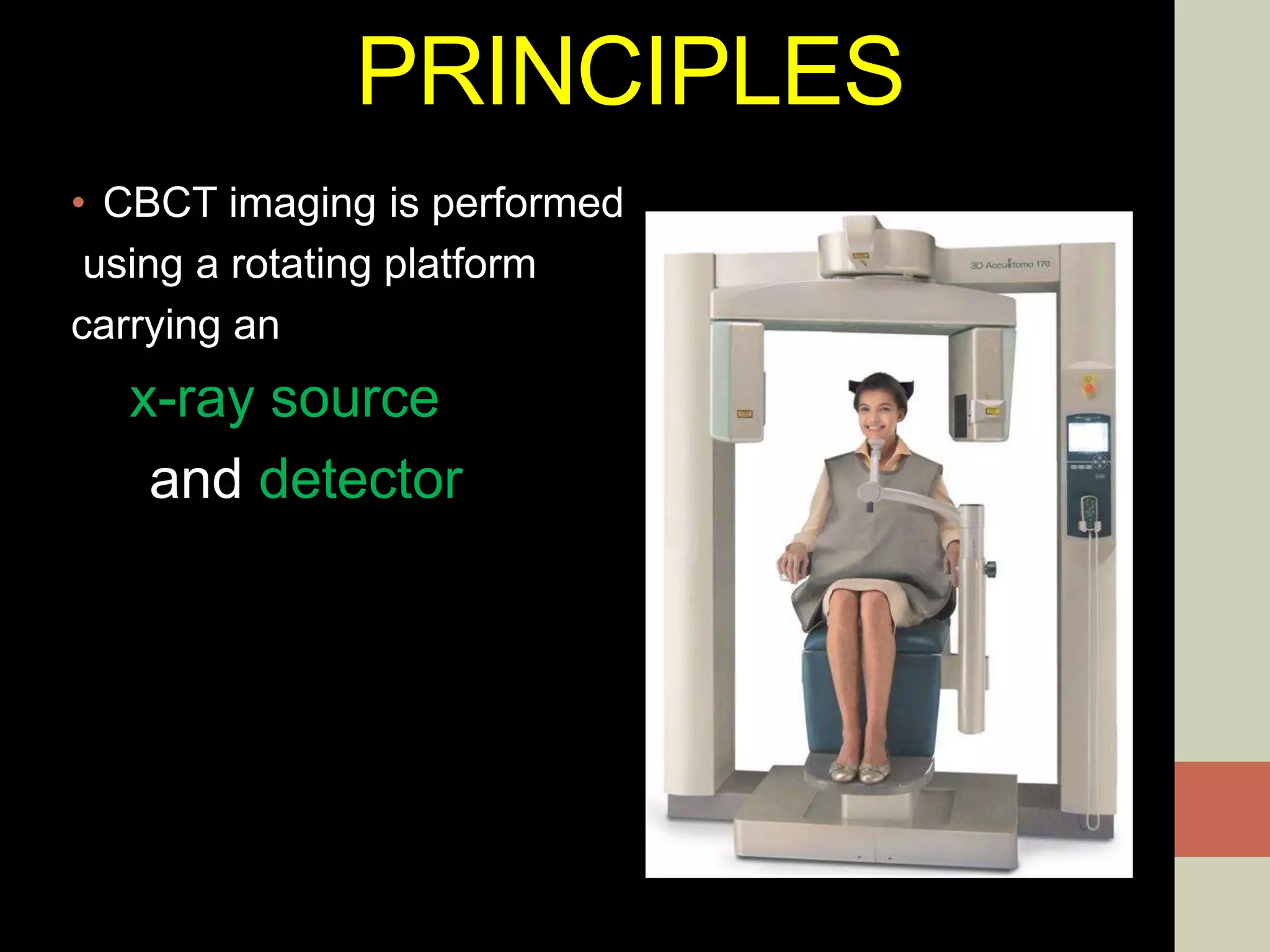
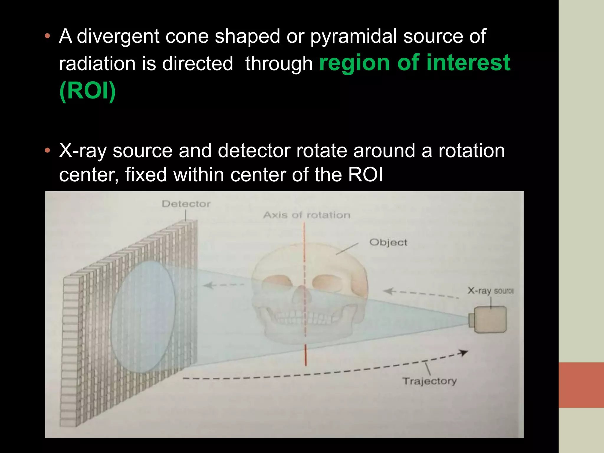
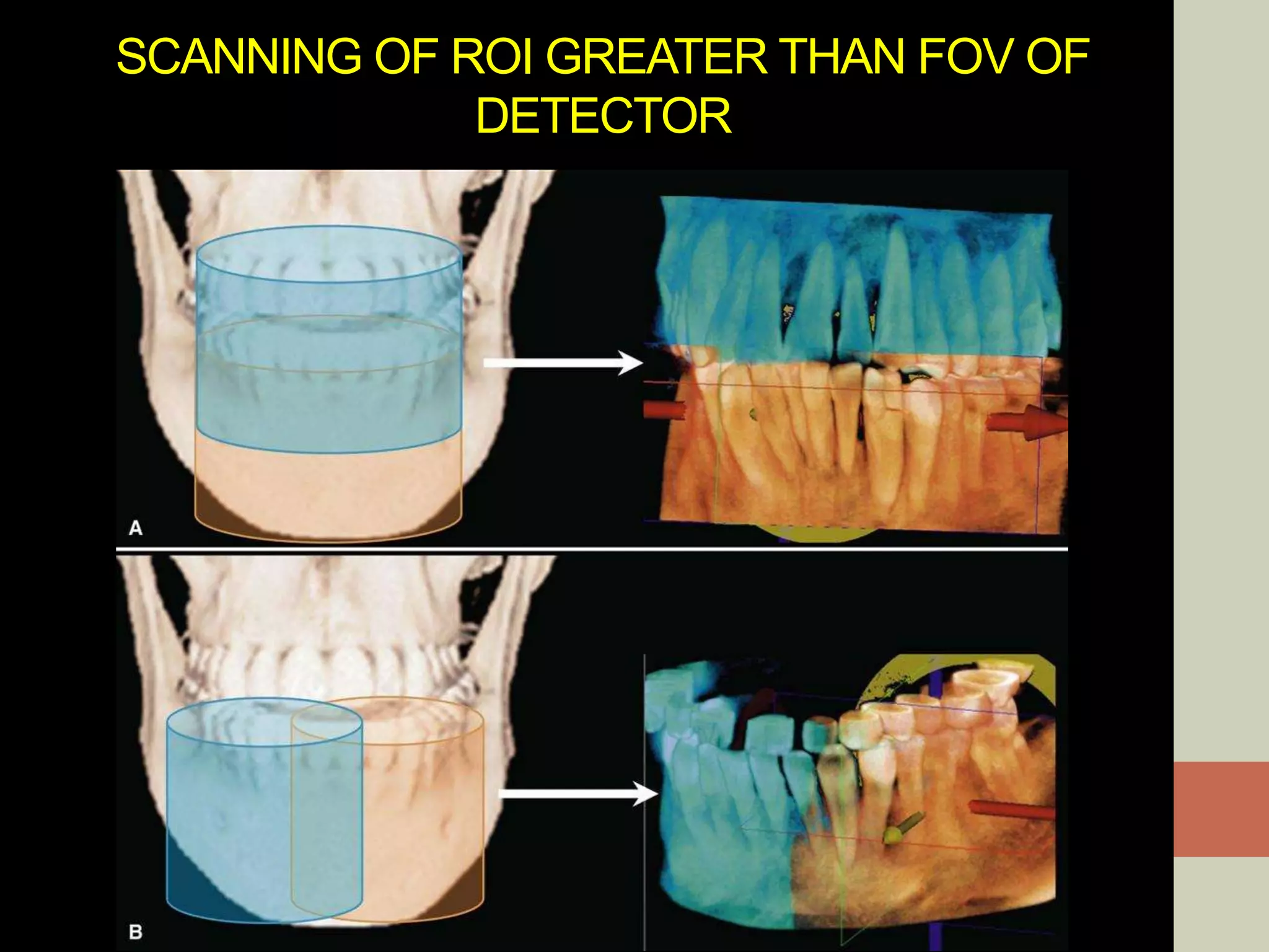
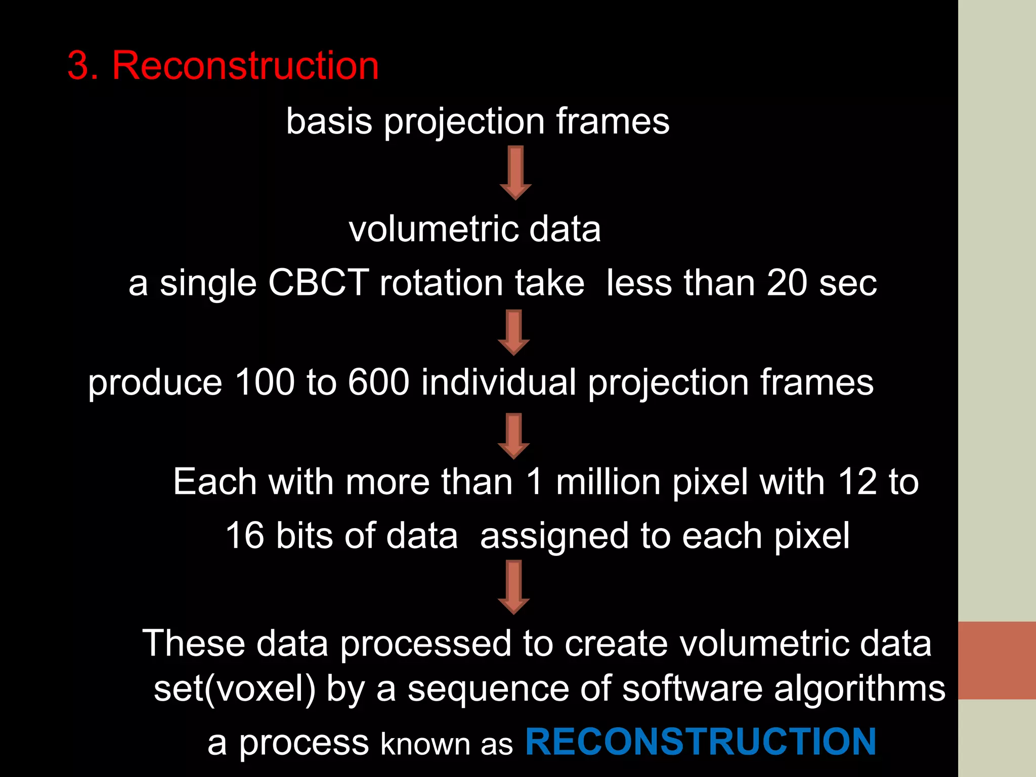
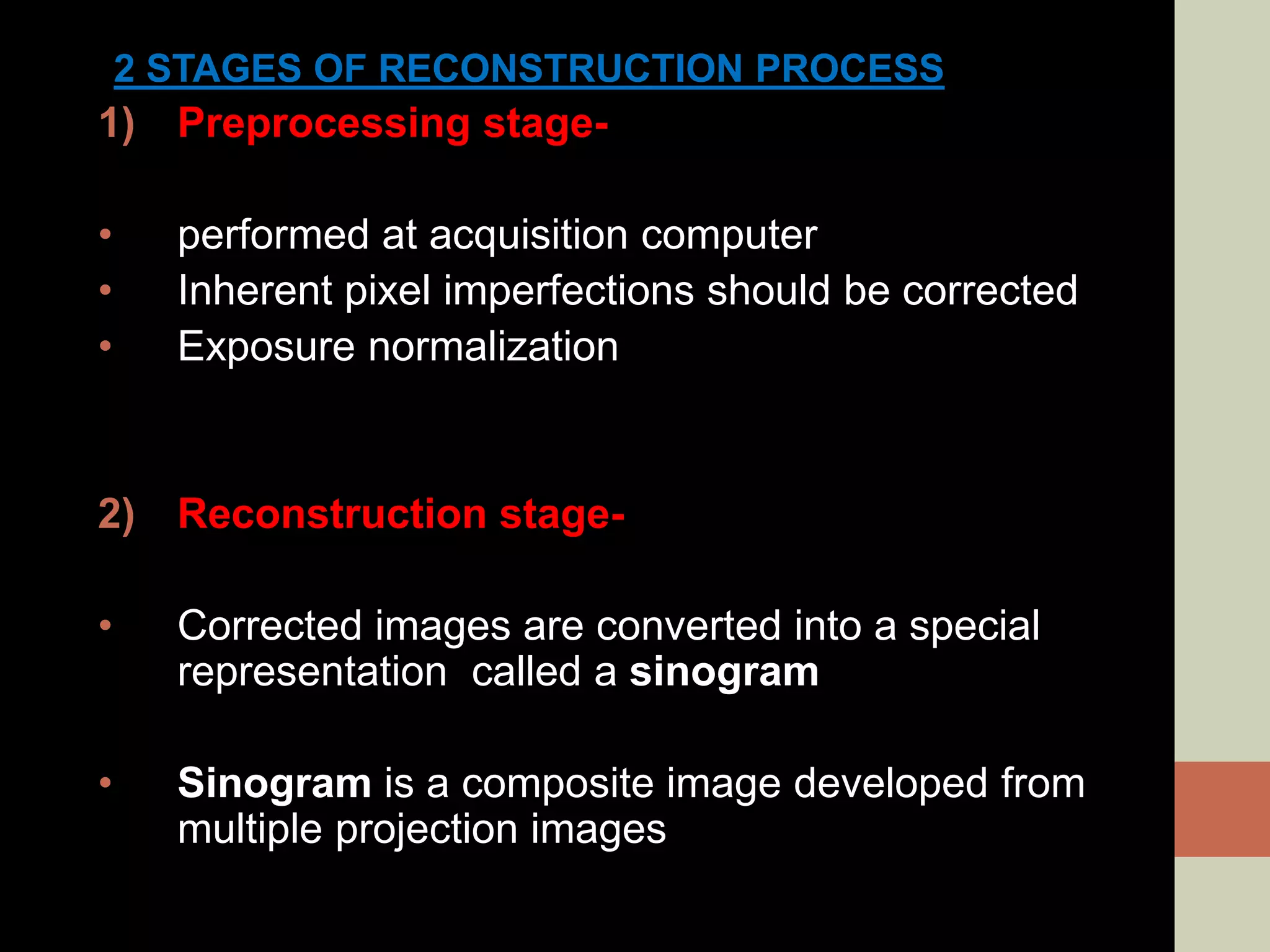
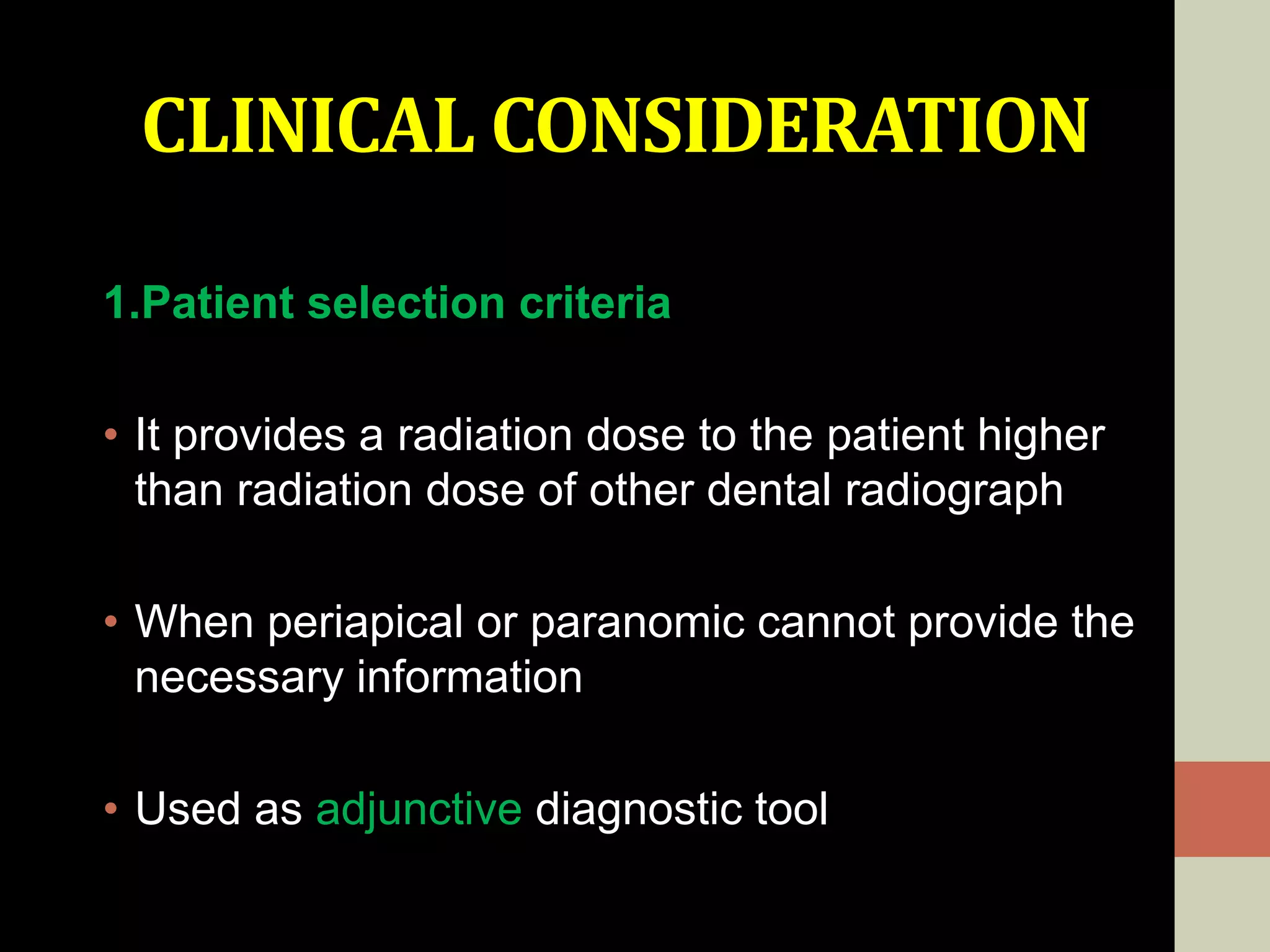
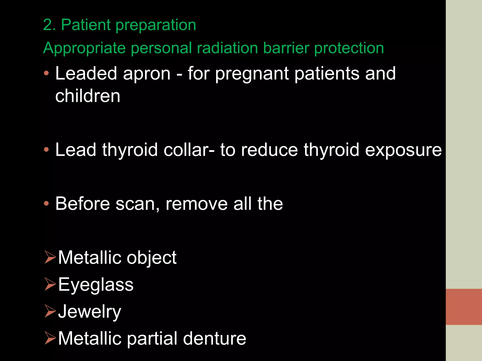
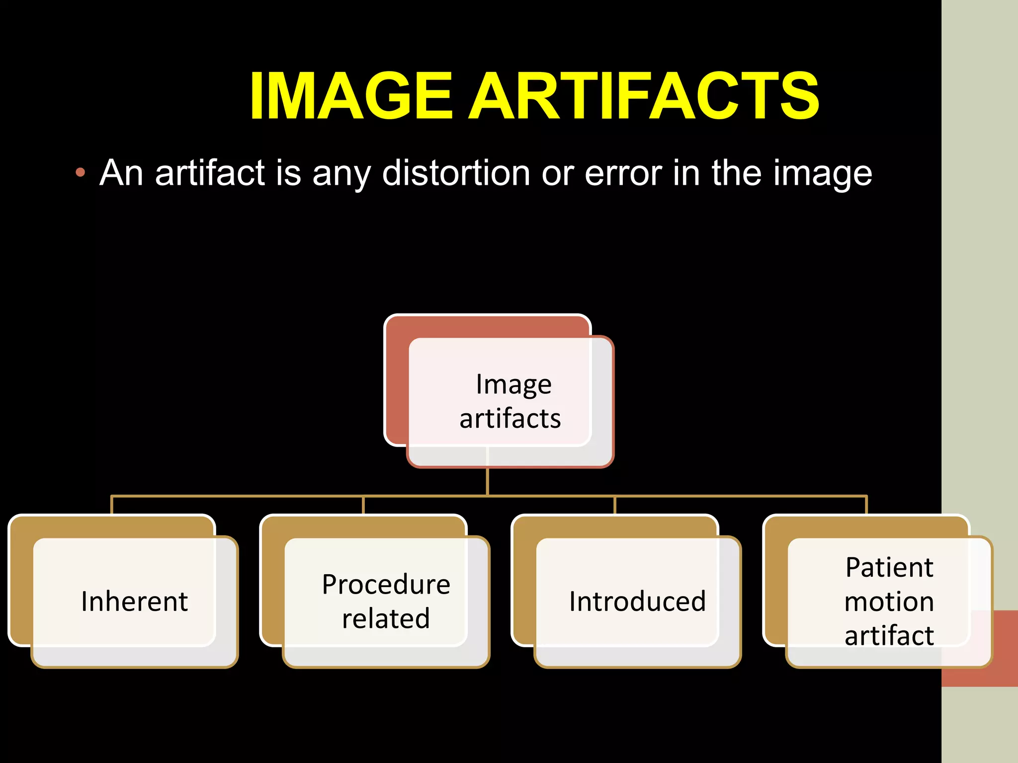
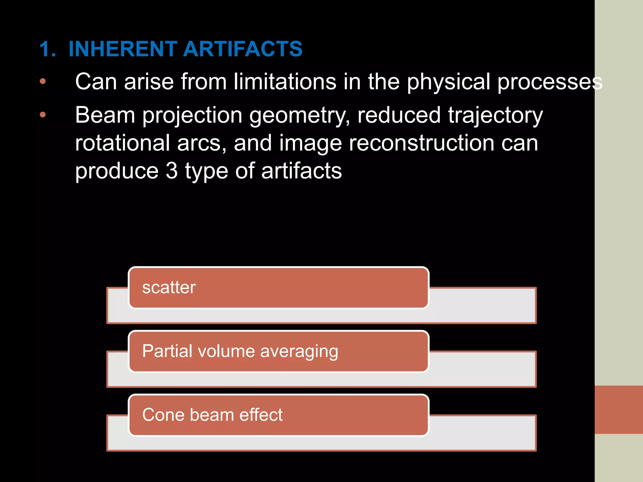
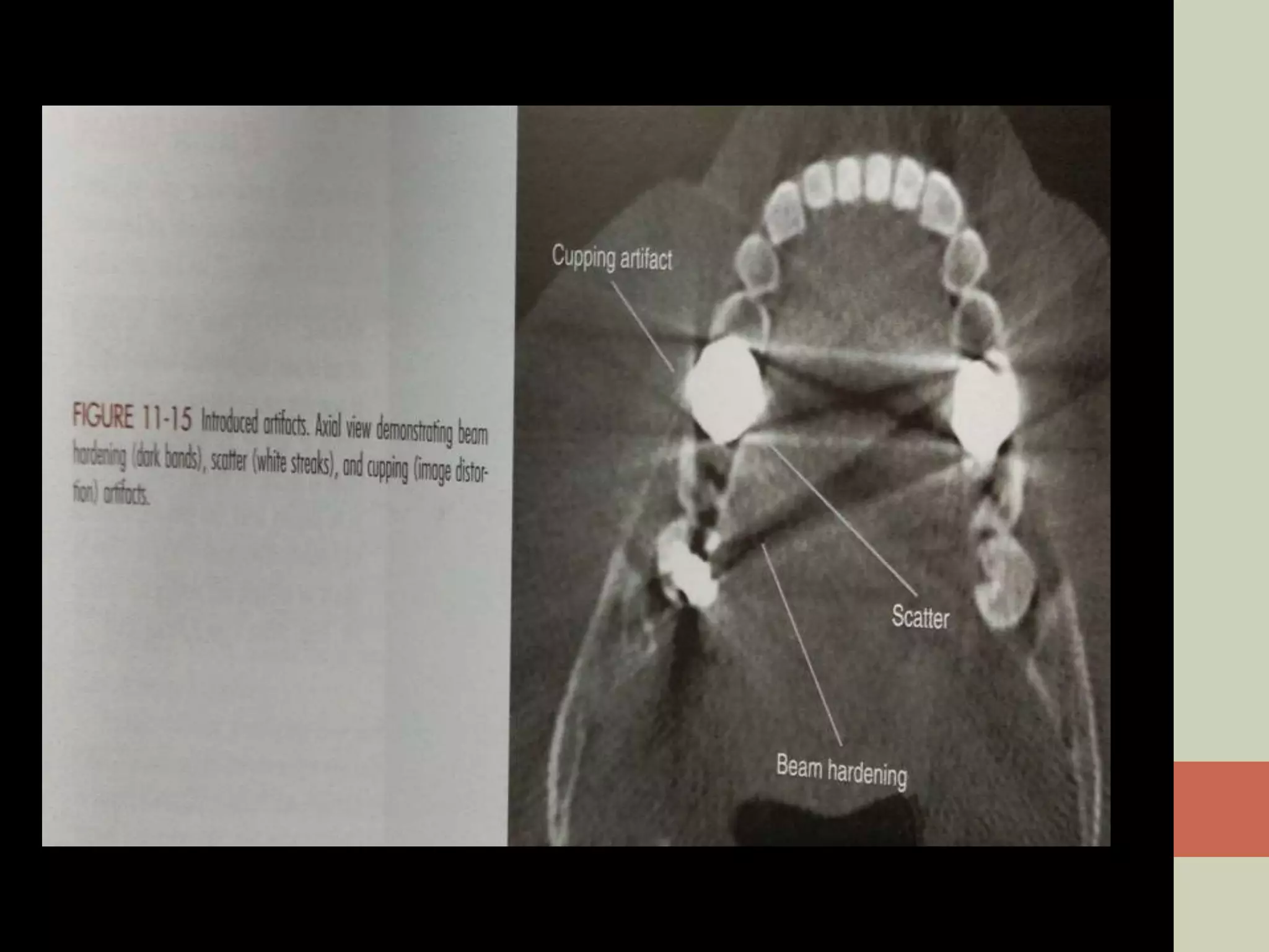
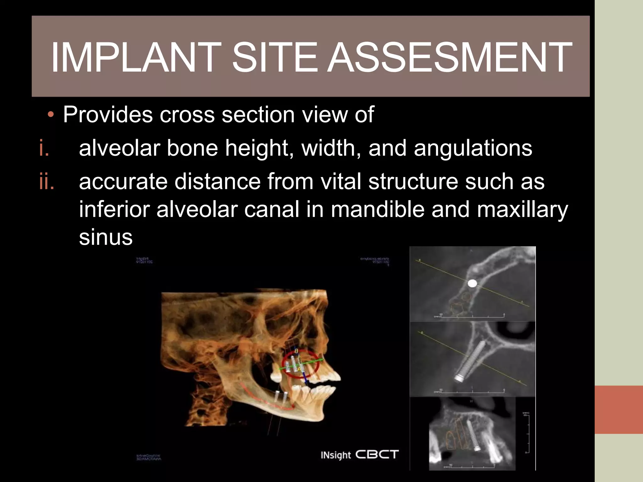
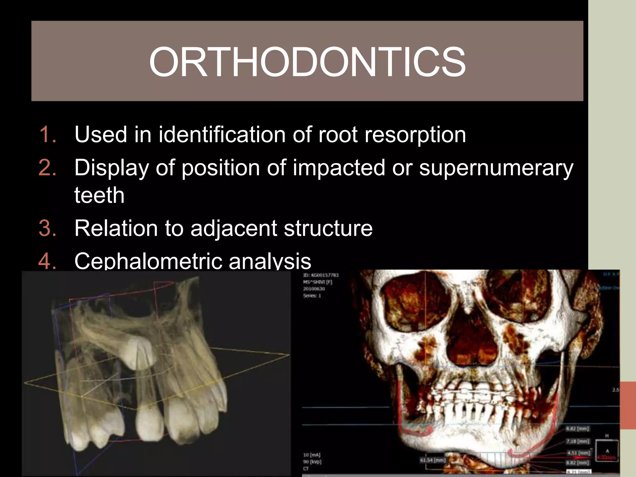
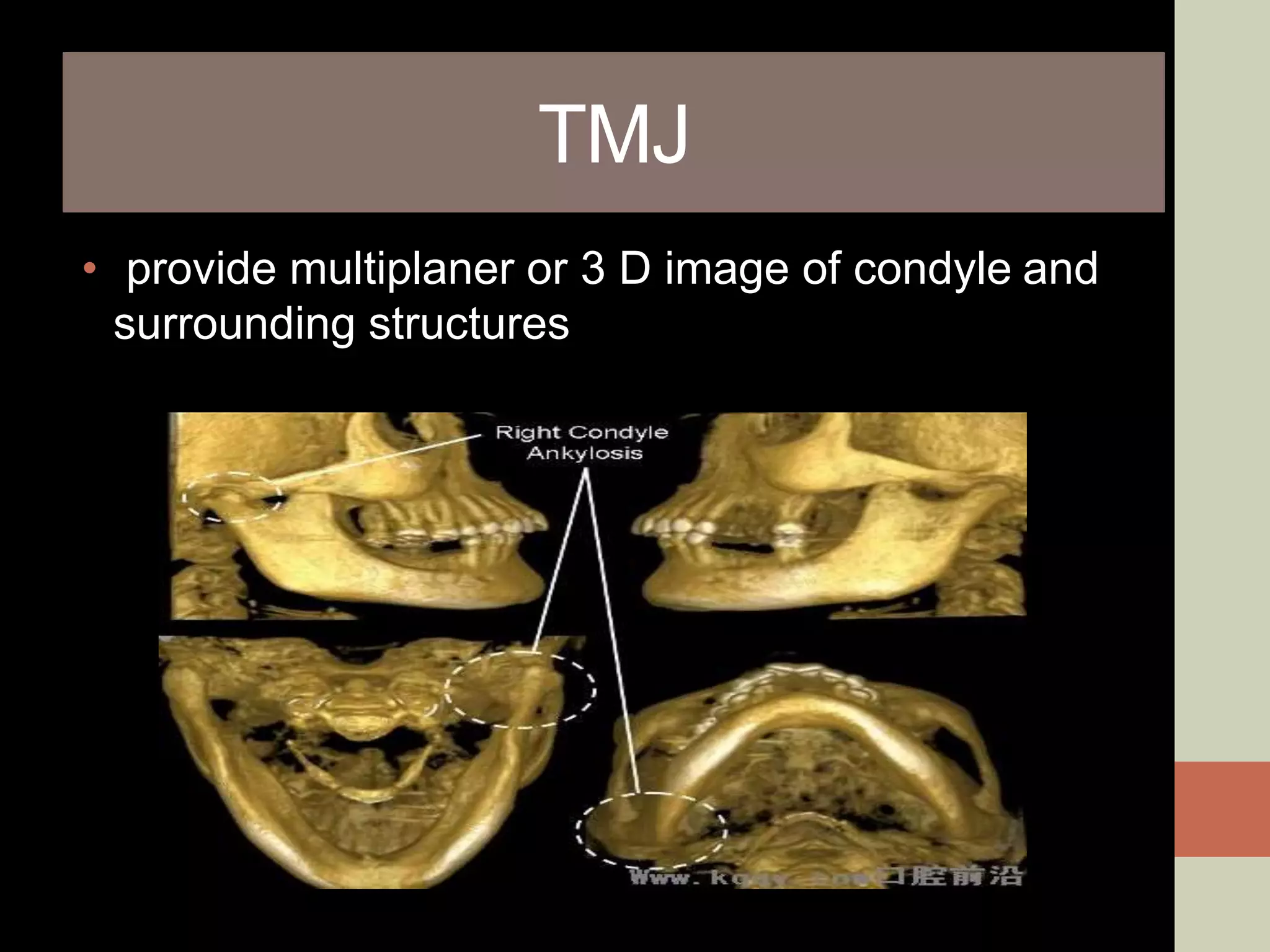
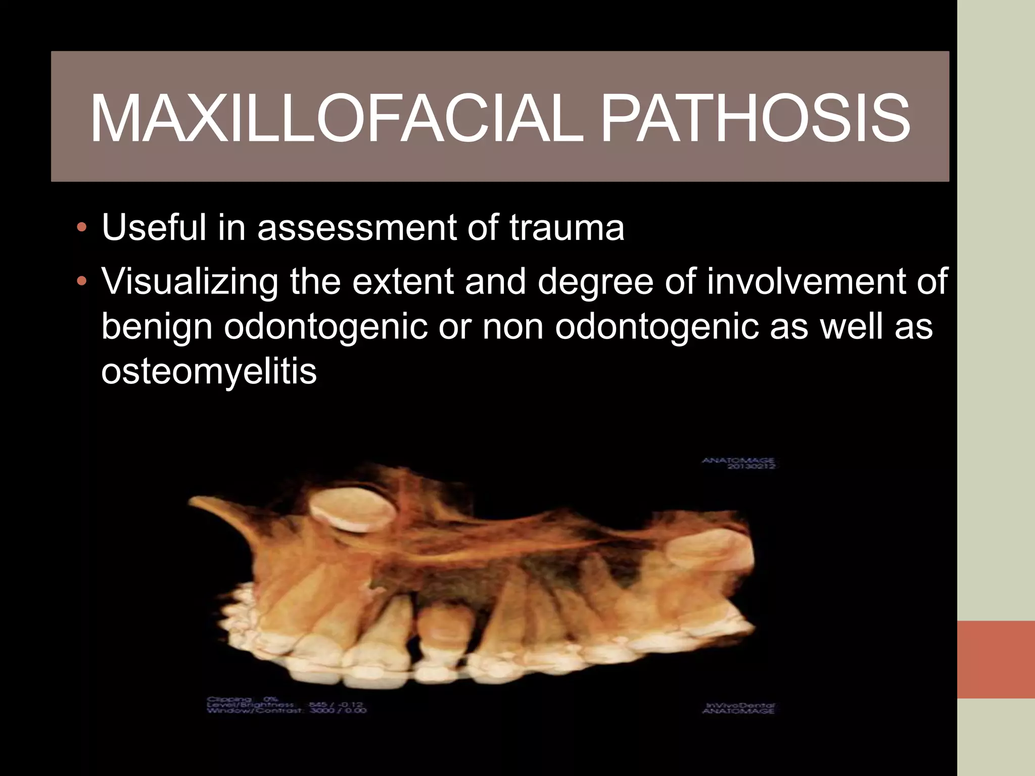
CBCT provides volumetric imaging with less radiation than medical CT. It involves an X-ray source and detector rotating around the patient to obtain multiple 2D projections, which are reconstructed into a 3D volume. This allows visualization of structures like bone and teeth from any angle. CBCT has numerous dental and maxillofacial applications like implant planning, orthodontics, and pathology assessment. While it provides more accuracy than 2D imaging, CBCT images can be affected by artifacts from scatter, motion, and metal objects. Overall, CBCT is a useful tool for evaluating anatomy in 3D.
Hey Guys, this presentation is all that a BDS graduate needs to know. A very basic yet important facts about CBCT.
Stay Safe
Regards
Battisi - Dr. Jasmine Singh
brief description about CONTENTS Introduction Principles of panoramic imaging Image layer Panoramic machines Panoramic film Patient positioning Interpreting the panoramic imaging INDICATION Advantages Disadvantages Conclusion References
3. INTRODUCTION • Panoramic imaging also called pantomography is a technique for producing a single tomographic image of facial structures that includes both the maxillary and mandibular dental arches and their supporting structures . • This is a curvilinear variant of conventional tomography.
4. PRINCIPLES OF PANORAMIC IMAGE FORMATION • Patero and Numata - describe the principles of panoramic radiography • based on the principle of reciprocal movement of x-ray source and an image receptor around a central point or plane called the image layer, in which the OBJECT of image is located. • OBJECT in front or behind this image are not clearly captured because of their movement relative to the centre of rotation of the receptor and the x-ray source.
5. The film and x-ray tubehead move around the patient in opposite directions in panoramic radiography
6. ROTATION CENTER The pivotal point or axis around which the cassette carrier and tube head rotate is termed rotation center Three basic rotation center used in panoramic radiography Double centre rotation Triple centre rotation moving centre rotation The location and number of rotational centers INFLUENCE size and shape of focal trough
7. IMAGE LAYER • Also known as focal trough • It is a three dimensional curved zone where the structures lying within this layer are reasonably well defined on final panoramic image. • The structures seen on a panoramic image are primarily those located within image layer. • OBJECTSoutside the image layer are blurred magnified are reduced in size. Even distorted to the extent of not being recognizable. • This shape of image layer varies with the brand of equipment used.
8. FOCAL TROUGH
9. FACTORS AFFECTING SIZE OF IMAGE LAYER: Arc path Velocity of receptor and X-ray tube head Alignment of x-ray beam Collimator width The location of image layer change with extensive machine used so recalibration may be necessary if consistently suboptimal images are produced. As a position of object is moved within the image layer size and shape of image layer change.
10. PANORAMIC UNIT
11. A, Orthophos XG Plus extraoral x-ray machine. B, Orthoralix 8500 extraoral x-ray machine. C, Example of a digital panoramic system
12. PARTS OF PANORAMIC UNITS a. x-ray tube head b. head positioner: chin rest notched bite block forehead rest lateral head support c. exposure controls
13. X-RAY TUBE HEAD: • Similar to intraoral x-ray tube head • Each has a filament to produce electrons and a target to produce x-rays • Collimator is a lead plate with narrow vertical slit • Narrow x-ray beam emerges from collimator minimize patient exposure to radiation
1
IDEAL IMAGE CHARACTERISTICS
FACTORS RELATED TO THE RADIATION BEAM
FACTORS RELATED TO THE OBJECT
FACTORS RELATED TO THE TECHNIQUE
FACTORS RELATED TO RECORDING OF THE ROENTGEN IMAGE OF THE OBJECT
DARK/ LIGHT IMAGE IDEAL IMAGE
IDEAL QUALITY CRIETRIA
this contains the occlusal radiography methods for both maxillary and mandibular different occusal radiographic techniques, principles, classification, indications
The Indian Dental Academy is the Leader in continuing dental education , training dentists in all aspects of dentistry and
offering a wide range of dental certified courses in different formats.
EVOLUTION AND DIGITAL EVALUATION USING CONE BEAM COMPUTERIZED TOMOGRAPHY, AND ITS USES IN CLINICAL ORTHODONTICS . PROTOTYPING MODALS, ITS APPLICATIONS IN VARIOUS FIELDS
Instructions for Submissions thorugh G- Classroom.pptxJheel Barad
This presentation provides a briefing on how to upload submissions and documents in Google Classroom. It was prepared as part of an orientation for new Sainik School in-service teacher trainees. As a training officer, my goal is to ensure that you are comfortable and proficient with this essential tool for managing assignments and fostering student engagement.
The Art Pastor's Guide to Sabbath | Steve ThomasonSteve Thomason
What is the purpose of the Sabbath Law in the Torah. It is interesting to compare how the context of the law shifts from Exodus to Deuteronomy. Who gets to rest, and why?
Palestine last event orientationfvgnh .pptxRaedMohamed3
An EFL lesson about the current events in Palestine. It is intended to be for intermediate students who wish to increase their listening skills through a short lesson in power point.
The French Revolution, which began in 1789, was a period of radical social and political upheaval in France. It marked the decline of absolute monarchies, the rise of secular and democratic republics, and the eventual rise of Napoleon Bonaparte. This revolutionary period is crucial in understanding the transition from feudalism to modernity in Europe.
For more information, visit-www.vavaclasses.com
How to Create Map Views in the Odoo 17 ERPCeline George
The map views are useful for providing a geographical representation of data. They allow users to visualize and analyze the data in a more intuitive manner.
Read| The latest issue of The Challenger is here! We are thrilled to announce that our school paper has qualified for the NATIONAL SCHOOLS PRESS CONFERENCE (NSPC) 2024. Thank you for your unwavering support and trust. Dive into the stories that made us stand out!
Welcome to TechSoup New Member Orientation and Q&A (May 2024).pdfTechSoup
In this webinar you will learn how your organization can access TechSoup's wide variety of product discount and donation programs. From hardware to software, we'll give you a tour of the tools available to help your nonprofit with productivity, collaboration, financial management, donor tracking, security, and more.
The Indian economy is classified into different sectors to simplify the analysis and understanding of economic activities. For Class 10, it's essential to grasp the sectors of the Indian economy, understand their characteristics, and recognize their importance. This guide will provide detailed notes on the Sectors of the Indian Economy Class 10, using specific long-tail keywords to enhance comprehension.
For more information, visit-www.vavaclasses.com
How to Split Bills in the Odoo 17 POS ModuleCeline George
Bills have a main role in point of sale procedure. It will help to track sales, handling payments and giving receipts to customers. Bill splitting also has an important role in POS. For example, If some friends come together for dinner and if they want to divide the bill then it is possible by POS bill splitting. This slide will show how to split bills in odoo 17 POS.
Unit 8 - Information and Communication Technology (Paper I).pdfThiyagu K
This slides describes the basic concepts of ICT, basics of Email, Emerging Technology and Digital Initiatives in Education. This presentations aligns with the UGC Paper I syllabus.
2. INTRODUCTION
CBCT IMAGING
• Most significant technology advancement in
maxillofacial imaging
• Shift from 2 D to a volumetric approach.
•
3. PRINCIPLES
• CBCT imaging is performed
using a rotating platform
carrying an
x-ray source
and detector
4. • A divergent cone shaped or pyramidal source of
radiation is directed through region of interest
(ROI)
• X-ray source and detector rotate around a rotation
center, fixed within center of the ROI
5. • During rotation, multiple sequential planer
projection images are obtained while the x-
ray source and detector move through an arc
of 180 to 360 degree
• Single projection image form raw primary
data, which is individually known as - basis,
frame or raw image
• Ususally several hundred 2-D basic images
from which the image volume is calculated.
• Complete series of images is called
PROJECTION DATA
9. X-RAY GENERATION
Patient Stabilization
Sitting, Standing, Supine
• With all system, immobilization of the patient’s head is
more important than position because any movement
degrades the final image
• Immobilization of head by -
1) Chin cup
2) bite fork
3) other head –restraint mechanism
11. X-ray generator
X-ray generation
continuous or pulsed
• When pulsed- exposure time is up to 50% less than
scanning time (this technique reduces patients radiation
dose)
• ALARA (As Low As Reasonable Achievable) principle of
dose optimization states that CBCT exposure factor
should be adjusted on the basis of patient’s size.
12. Scan Volume/field of view(FOV)
*Detector size
*Shape
*Beam projection geometry
*Ability to collimate the beam
13. • It is desirable to limit the field size to the
smallest volume that images the ROI.
• This procedure reduces unnecessary
exposure to the patient and produces the
best image by minimum scattered radiation,
which degrade image quality
16. Scan factor
• Number of images forming the “projection data”
throughout the scan is determined by-
1. Detector frame rate(no. of image acquired per
sec.)
2. Completeness of the trajectory arc (180 to 360)
3. Rotation speed of source and detector
17. IMAGE DETECTOR
larger and bulkier lighter in weight
circular basis image area rectangular
spherical volume cylindrical vol.
cesium iodide scintillator
CBCT units
Image intensifier
tube/charge-coupled
device(II/CCD)
Flat panel
detector(FPDs)
18. Voxel- Volume element
• Individual volume element is VOXEL
• Voxels form the volumetric data set
• CBCT units provide voxel resolution
• that are isotropic - equal in all 3 dimension
• Determinant of voxel is- Pixel size of detector
Detector with small pixel
Capture few x-ray photon per voxel
19. 3. Reconstruction
basis projection frames
volumetric data
a single CBCT rotation take less than 20 sec
produce 100 to 600 individual projection frames
Each with more than 1 million pixel with 12 to
16 bits of data assigned to each pixel
These data processed to create volumetric data
set(voxel) by a sequence of software algorithms
a process known as RECONSTRUCTION
20. 2 STAGES OF RECONSTRUCTION PROCESS
1) Preprocessing stage-
• performed at acquisition computer
• Inherent pixel imperfections should be corrected
• Exposure normalization
2) Reconstruction stage-
• Corrected images are converted into a special
representation called a sinogram
• Sinogram is a composite image developed from
multiple projection images
21. CLINICAL CONSIDERATION
1.Patient selection criteria
• It provides a radiation dose to the patient higher
than radiation dose of other dental radiograph
• When periapical or paranomic cannot provide the
necessary information
• Used as adjunctive diagnostic tool
22. 2. Patient preparation
Appropriate personal radiation barrier protection
• Leaded apron - for pregnant patients and
children
• Lead thyroid collar- to reduce thyroid exposure
• Before scan, remove all the
Metallic object
Eyeglass
Jewelry
Metallic partial denture
23. • Patient motion can be minimized by
Head stabilization
Chin cups to posterior or lateral head
support
• Patient should be directed to remain still as
possible before exposure, to breathe slowly
through nose, and to close the eyes.
24. 3. Imaging protocol
• Develop to produce image of optimal quality with
the least amount of radiation exposure to the
patient
Exposure setting
Spatial resolution
25. 1. Exposure setting
• Quality and quantity of x-ray beam depend on
i. Tube voltage(kVp)
ii. Tube current( mA)
• CBCT unit manufacturers approach setting
exposure in 2 ways-
1. Selection of fixed exposure setting
2. Allow operator manual adjustment of kVp or mA
26. 2. Spatial resolution
• Ability of an image to reveal fine detail
• Determined by
i. Pixel size
ii. Beam projection geometry
iii. Patient scatter
iv. Focal spot size
v. Number of basis image
vi. Reconstruction algorithm
27. 3. Scan time and number of projection
adjusting the detector frame rate
increase the number of basis image projections
reconstructed image with fewer artifacts and better
image quality
28. 4. Archiving, export, and distribution
• Process of CBCT imaging produces 2 data products
1. Volumetric image data from the scan
2. Image report generated by the operator
• Both set of data must be archived and distributed
29. IMAGE ARTIFACTS
• An artifact is any distortion or error in the image
Image
artifacts
Inherent
Procedure
related
Introduced
Patient
motion
artifact
30. 1. INHERENT ARTIFACTS
• Can arise from limitations in the physical processes
• Beam projection geometry, reduced trajectory
rotational arcs, and image reconstruction can
produce 3 type of artifacts
scatter
Partial volume averaging
Cone beam effect
31. Scatter-
• Result from x-ray photons that are diffracted
from their original path after interaction with
matter
Partial volume averaging-
• It occur when the selected voxel size of the scan
is larger than the size of the object being imaged
32. Cone beam effect-
• Is a potential source of artifacts, especially in the
peripheral portion of scan volume
• Can result in
i. Image distortion
ii. Greater peripheral noise
• Clinically, the effect can be reduced by positioning
of ROI in the horizontal plane of x-ray beam.
33. 2. Procedure related artifacts
• Under sampling of the object can occur when too few
basis projections are provided for image reconstruction or
when rotational trajectory arc are incomplete
• Reduced data sample leads to:-
1. misregistration
2. noisier image
• which appear as fine striations in the image
34. 3. Introduced artifacts
• An x-ray beam pass through an object ,lower energy
photons are absorbed in preference to higher energy
photons, this phenomenon is known as
beam hardening
• Can result in 2 type of artifacts
1. Distortion of metallic structure as a result of differential
absorption, known as cupping artifact
2. Streaks and dark bands, which when present b/w 2
dense objects ,create extinction or missing value
artifacts
35.
36. 4. Patient motion artifacts
• Can cause misregistration of data which appear as
double contours in the reconstructed image
• Problem can be minimized by restraining the head
and using a short scan time as possible
37. ADVANTAGES OF CBCT
• Less cost
• Less space required rapid, quick scanning time
• Radiation dose reduction
• Image accuracy
• Reduced image artifacts
• Unlimited number of views
• Imaging can be obtained at any angle
• Superior representation of bony structure
• Powerful diagnostic 3D planning tool
38. DISADVANTAGES OF CBCT
Image noise –
• Because radiation from the source transmitted through
tissue in the body, the receptor receives non uniform
information from radiation scattered in many directions-
termed as noise.
• Noise is 0.05 to 0.15 with conventional CT and can be
as large as 0.4 to 2 in CBCT
Poor soft tissue contrast-
• Scattered radiation contributes to increased noise of the
image which reduces the contrast of the cone beam
system
40. IMPLANT SITE ASSESMENT
• Provides cross section view of
i. alveolar bone height, width, and angulations
ii. accurate distance from vital structure such as
inferior alveolar canal in mandible and maxillary
sinus
41. ORTHODONTICS
1. Used in identification of root resorption
2. Display of position of impacted or supernumerary
teeth
3. Relation to adjacent structure
4. Cephalometric analysis
43. MAXILLOFACIAL PATHOSIS
• Useful in assessment of trauma
• Visualizing the extent and degree of involvement of
benign odontogenic or non odontogenic as well as
osteomyelitis