

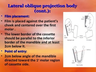
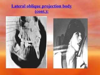
![1] Lateral oblique projection:
• 2 views for mandibular projection;
• a) body projection:
• For demonstration premolar-molar region
and inferior border of the body of the
mandible.
• Head position: Head tilted to the side to
be examined with the mandible
protruded.](https://image.slidesharecdn.com/extraoraltechniquespartifinal-140119090806-phpapp02/85/Extra-oral-Radiology-Techniques-I-14-320.jpg)
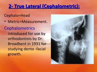
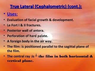
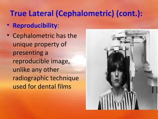
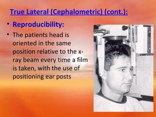
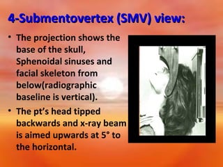
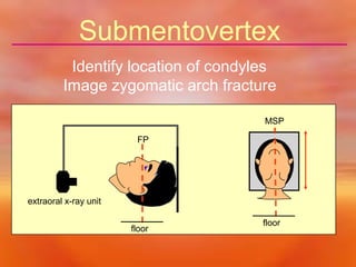
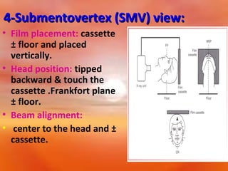
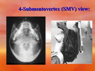


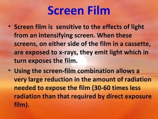
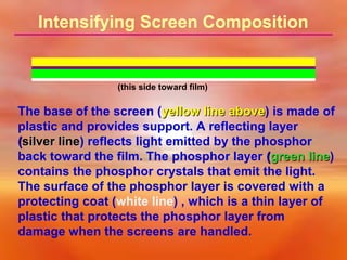
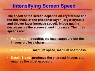
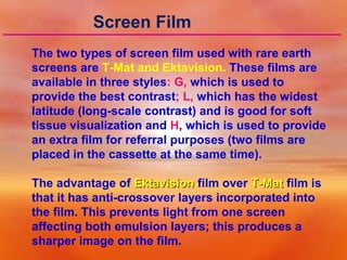
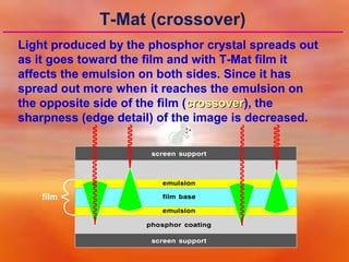
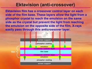
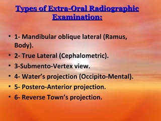
This document provides information on extraoral radiographic techniques. It discusses various extraoral views including lateral oblique, cephalometric, submentovertex, and zygomatic arch views. For each view, it describes the positioning of the patient's head, placement of the radiographic cassette and film, and path of the x-ray beam. It also discusses the components and function of screen-film systems used in extraoral radiography, including intensifying screens, screen speeds, and the advantages of Ektavision film over T-Mat film. Common cephalometric landmarks and their use in orthodontic assessment are also summarized.


