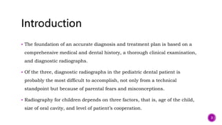
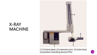
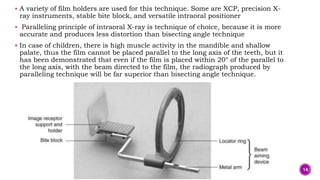
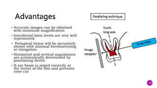
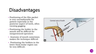
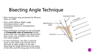
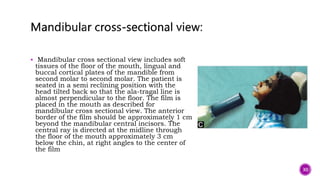
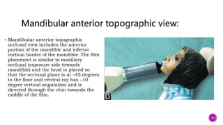
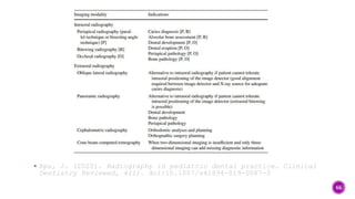
SlideShare a Scribd company logo
Presented by
Dr Simran Vangani
1
 Introduction
 History
 X-ray machine components
 Radiographic Techniques
 Intraoral Radiography
 Extra-oral Radiography
 Radiation Protection
 Behavioral Considerations in Pedodontics Radiography
 Conclusion
2
 The foundation of an accurate diagnosis and treatment plan is based on a
comprehensive medical and dental history, a thorough clinical examination,
and diagnostic radiographs.
 Of the three, diagnostic radiographs in the pediatric dental patient is
probably the most difficult to accomplish, not only from a technical
standpoint but because of parental fears and misconceptions.
 Radiography for children depends on three factors, that is, age of the child,
size of oral cavity, and level of patient’s cooperation.
3
 The X-ray was discovered in November 1895 by Wilhelm
Conrad Roentgen, a professor of physics at the
University of Würzburg in Germany.
 Roentgen presented a paper on his discovery in late December,
and in January 1896, Dr Otto Walkhoff , a dentist in Germany,
made the first dental use of an X-ray and radiographed a lower
premolar
 In 1913, William D Coolidge invented the hot cathode X-ray tube
which is the prototype of X-ray tubes today, and in 1923, the first
American dental X-ray machine was manufactured by Victor X-ray
Corporation which later became General Electric X-ray
Corporation. 4
5
 Control panel: This consists of an on/off
switch, indicator lights, an exposure
button, and control devices (time, Kvp, mA)
to regulate the X-ray beam. The control
panel is plugged into an electrical outlet
and appears as a panel or cabinets that are
mounted.
 Extension arm: The wall mounted
extension arm suspends the X-ray tube
head and houses the electrical wires. The
purpose of the cathode is to supply the
electrons necessary to generate X-rays.
 Cathode:Produced the electrons that are
accelerated toward the positive anode. This
includes tungsten filaments or coiled wire
made of tungsten, which produces
electrons when heated, and a molybdenum
cup, which focuses the electrons into a
narrow beam and directs the beam across
the tube toward the tungsten targets of the
anode.
6
 Anode-A positive electrode consists of a
wafer thin tungsten plate embedded in a
solid copper rod with the purpose of
converting electrons into X-ray photon. It
includes a tungsten target, or plate of
tungsten, which serves as a focal spot and
converts bombarding electron into X-ray
photons, and a copper stem, which
functions to dissipate the heat away from
the tungsten target.
 Amperage: It is the measurement of the
number of electrons moving through a
conductor
 Voltage : It is the measurement of electrical
force that causes electrons to move from
negative pole to a positive one
7
 They are invisible
 They travel at the same speed of light—3 × 10⁸m/s
 They travel in a straight line
 They cannot be deflected
 They affect photographic plates
 They produces fluorescence with some substances, for example, bario-
palladium crystals
 They can penetrate opaque objects
8
 Multiple radiographic techniques must be used to manage the wide range of
pediatric and special-needs dental patients. The patient’s size and ability to
cooperate must be considered when a radiographic technique is selected.
9
 Intraoral tube heads should generate between 60 and 70 kVp to produce
adequate diagnostic images. The timer must be accurate to allow for short
exposure times.
 Radiation-sensitive (rapid) image receptors should be used at all times.
Collimation of the radiation beam is advised to reduce the irradiated surface
area to the size of the image receptor.
 There are several types of intraoral radiographs, each of which has specific
indications and limitations.
10
 Periapical radiographs should show the crown of the tooth and at least 3 mm
beyond the apex of the tooth. To achieve this coverage, one can use either the
paralleling technique or the bisecting angle technique. The paralleling
technique is preferred because of its accuracy.
Paralleling Technique
 Also called right angle technique/long cone technique/ MacCormack’s
technique/Fitzgerald technique.
 Dr Gordon Fitzgerald is the pioneer of this technique.
 The primary purpose of this is to obtain a true radiographic orientation of
teeth and supporting structures.
 It is based on the principle that central ray should be focused perpendicular
to long axis of the film with the X-ray film being parallel to long axis of tooth.
11
12
 To obtain parallelism and to reduce distortion, the film is placed away from tooth,
but the use of long source to object distance reduces the size of the apparent focal
spot and leads to less magnification and increased definition
 Film holders are used to ensure proper position of the film and to maintain it in
position
 To assure that the periapical areas will be projected onto the film, it is necessary
that the film be positioned away from the teeth and toward the center of the
mouth, where the maximum height of the palate can be utilized
 For maxillary projections, the superior border of the film will generally rest at the
height of the palatal vault in the midline. For mandibular projections, the film will
be used to displace the tongue lingually to allow the inferior border of the film to be
depressed into the floor of the mouth away from the mucosa on the lingual surface
of the mandible .
13
 A variety of film holders are used for this technique. Some are XCP, precision X-
ray instruments, stable bite block, and versatile intraoral positioner
 Paralleling principle of intraoral X-ray is technique of choice, because it is more
accurate and produces less distortion than bisecting angle technique
 In case of children, there is high muscle activity in the mandible and shallow
palate, thus the film cannot be placed parallel to the long axis of the teeth, but it
has been demonstrated that even if the film is placed within 20° of the parallel to
the long axis, with the beam directed to the film, the radiograph produced by
paralleling technique will be far superior than bisecting angle technique.
14
 Accurate images can be obtained
with minimum magnification
 Interdental bone levels are very well
represented
 Periapical tissue will be accurately
shown with minimal foreshortening
or elongation
 Horizontal and vertical angulations
are automatically determined by
positioning device
 X-ray beam is aimed correctly at
the center of the film and prevents
cone cut
15
 Positioning of the film packet
is very uncomfortable for
patient especially in the
posterior aspect of teeth, often
causing gagging
 Positioning the holder in the
mouth will be difficult for
inexperienced operators
 Anatomy of mouth sometimes
makes the technique difficult
 Positioning the holders in the
lower third molar region can
be very difficult.
16
 This technique was promoted by Weston
Price in 1904
 Also called Millers Right angle
technique/short cone
technique/isometric triangulation
technique
 This technique is based on the principle
of Cieszynski rule of isometry which
states that two triangles are equal when
they share one complete side and have
two equal angles
 In this technique, the film is placed
close to the teeth and central ray is
directed at right angles to the line
bisecting the angle formed by the plane
of the film and the long axis of the tooth
17
 Although film holders are not used in this technique for positioning, we have some
special film holders like Renn-Snap or Snap-A-Ray that can be used to prevent
exposure of patient’s hand, avoid slippage of film in mouth, and prevent cone cut.
Angulations of tube head
 Horizontal angulation is 0°
 Vertical angulation is different for all teeth
Maxillary
 Incisor: +40°,
 Premolar: +30°,
 Canine: +45°,
 Molar: +20°
 In deciduous: Anterior: +45°, Posterior: +30°
18
 Mandibular
 Incisor: −15°,
 Premolar: −10°,
 Canine: −20°,
 Molar: −5°
 In deciduous: Anterior: −15°, Posterior: −10°
19
 Positioning of film or film packet will be reasonably comfortable for patient
and for operator in all areas of mouth
 Positioning of film is simple and quick
 If we give proper angulation, there will not be any distortion of image
20
 Improper vertical angulations may lead to shortening or lengthening of image ™
 Interdental bone loss will be poorly demonstrated
 Shadow of zygomatic bone frequently overlies the roots of upper molars
 ™
Horizontal and vertical angles have to be assessed for every exposure,
considerable skill is needed
 Cone-cut may result if improper positioning of tube is done
 Incorrect horizontal angulation will result in horizontal overlapping of crowns
and roots
 Crowns of teeth are often distorted, thus preventing detection of proximal
caries.
21
Bitewing Radiography
 Developed by Howard Raper in 1925
 Periapical films are used to record the
coronal portions of both maxillary and
mandibular teeth in one image
 Size 1 film is used in children and size
2 films are used in adults
 Used mostly to detect interproximal
caries and to check the level of bone
22
23
 The head is positioned such that
the midsagittal plane is
perpendicular and the ala-tragus
line is parallel to the floor.
 The lower edge of the film is placed
in the floor of the mouth between
the tongue and the lingual aspect
of the mandible and the bite tab is
placed on the occlusal surfaces of
the mandibular teeth.
 The film is positioned to cover all
the region of concern. The central
ray enters at the occlusal plane at
a point below the pupil, vertical
angle being +8 degrees.
 A tab or bite platform or unibite
film holders can be used to
position the film parallel to the
occlusal plane
24
Occlusal Radiography
 Used to take the jaw radiographs
of maxilla and mandible to detect
large lesions, fractures,
impactions, supernumerary teeth
and to localize foreign bodies
 The film is partially held in
between teeth and partially
supported by patient
 The vertical angulation for maxilla
is +45° and for mandible is −55°.
25
 Determine the presence, shape and position of midline supernumerary teeth .
 Determine impaction of canines
 Determine the presence or absence of incisors
 Assess the extent of trauma to teeth and anterior segments of the arches
 In case of trismus and trauma, where the patient cannot open the mouth
completely
 Determine the medial and lateral extent of cysts and tumors.
26
 Occlusal radiographs can be either maxilla or mandible.
 Maxillary and mandibular occlusal radiographs can be of 3 types:
1. Anterior topographic view
2. Cross sectional view
3. Lateral topographic view
27
 Maxillary anterior topographic radiograph is
indicated to view anterior maxilla and its
dentition. While taking the radiograph the
patient’s head is adjusted so that the
occlusal plane is horizontal to the floor. The
film is placed crosswise in the mouth with
exposure side towards maxilla and the
posterior border touching the rami
horizontally. The patient is asked to close
the mouth gently. Central ray is directed
through the tip of the nose toward the
middle of the film with approximately +45
degrees vertical angulation and 0 degrees
horizontal angulation
28
 Maxillary cross sectional view shows palate,
zygomatic process of maxilla, nasolacrimal
canals, anteroinferior aspects of antrum and
nasal septum.
 The patients head is adjusted so that the occlusal
plane is horizontal to the floor. The film is placed
in the mouth crosswise with exposure side
towards maxilla and the posterior border
touching the rami horizontally. The patient is
asked to close his mouth gently. The central ray
is directed at a vertical angulation of +65 and a
horizontal angulation of 0 degrees to the bridge of
the nose just below the nasion, towards the
middle of the film.
29
 Mandibular cross sectional view includes soft
tissues of the floor of the mouth, lingual and
buccal cortical plates of the mandible from
second molar to second molar. The patient is
seated in a semi reclining position with the
head tilted back so that the ala-tragal line is
almost perpendicular to the floor. The film is
placed in the mouth as described for
mandibular cross sectional view. The anterior
border of the film should be approximately 1 cm
beyond the mandibular central incisors. The
central ray is directed at the midline through
the floor of the mouth approximately 3 cm
below the chin, at right angles to the center of
the film
30
 Mandibular anterior topographic
occlusal view includes the anterior
portion of the mandible and inferior
cortical border of the mandible. The film
placement is similar to maxillary
occlusal (exposure side towards
mandible) and the head is placed so
that the occlusal plane is at –45 degrees
to the floor and central ray has –10
degree vertical angulation and is
directed through the chin towards the
middle of the film.
31
Specialized Intraoral Radiographic Technique
 This technique is used exclusively for children and called bent film radiographic
technique
 This technique works well with young children, requires little skill as patient
bites down
 Used when young patient do not tolerate the placing of a film holder inside their
mouths
 Top portion of the film is bent at right angle and this serves as a bite block to
hold the film in place. Patient is instructed to bite the film slowly and radiograph
is taken. Care must be taken to straighten the film before processing
 This can be used both with paralleling cone or bisecting angle technique
 Size 1 or 2 film should be used.
32
33
PANORAMIC RADIOGRAPHY
 It was developed by Numata (1933)
 This is also called
orthopantomography/maxillomandib
ular
radiography/pantomography/rotatio
nal tomography.
 This uses a mechanism by which the
X-ray film and the source of the X-
rays move simultaneously in
opposite direction at the same speed.
34
35
•X-ray tube head. Produces the x-ray beam.
The beam is aimed slightly upwards, towards
the slot in the cassette holder.
•Diaphragm. The x-ray beam is collimated by
the diaphragm to form a vertical slit-shaped
beam. The x-ray beam width should be no
greater than 5 mm.
•Cassette holder. Has a metal sheet at the
front that prevents scattered x-ray photons
reaching the cassette, which would otherwise
degrade the image. There is a narrow vertical
slot in the holder directly opposite the x-ray
source. This ensures that only a small amount
of the film is exposed at one time.
•Cassette carriage. Moves the cassette behind
the cassette holder during the exposure.
•Bite block. Used to locate both upper and
lower incisor teeth in an edge-to-edge
relationship in the focal layer. It also separates
the upper and lower teeth to prevent overlap.
•Light-beam markers. Used to position the
patient correctly, to ensure that the teeth fall in
the focal layer.
•Head-holding apparatus. Allows the patient’s
head to be immobilised once accurately
positioned.
•Handles. Minimise movement of the patient
36
 Condylar fracture
 Traumatic cysts
 Evaluation of tooth development (mixed dentition)
 Developmental anomalies
 Disabled child.
37
 Broad anatomic region imaged
 Relatively low radiation dose
 Convenience, speed, and ease
 Useful in patients who are unable to open mouth.
38
 Lack of image detail for diagnosis of early carious lesion.
 Cost of X-ray machine
 Overlaps images of teeth
 Staying completely immobile for 15 seconds may not be possible for very
young children.
39
 Evaluation of gross carious status
 Assessment of advance bone heights
 Extensive cystic and tumor cases
 Assessment of mixed dentition
 Overall assessment of bone pattern
 Fractures (trauma)
 Preliminary assessment of maxillary sinus diseases
 General assessments of condyles morphology
 Pre- and postoperative evaluation of oral surgical procedures and orthodontic treatment
 Changes in alveolar bone due to systemic diseases like leukemias, Paget disease
 Evaluation of third molars
 To assess lesions in edentulous jaws
 To assess the radiologic assessment of implant site
 Patients who have gagging sensation to intraoral films
 Ankylosis of temporomandibular joint (TMJ)
 Patients with restricted mouth opening
 Evaluation of tooth development
40
XERORADIOGRAPHY
 Xeroradiography which is a method of imaging uses the xeroradiographic
copying process to record images produced by diagnostic X-rays
 It differs from halide film technique; in that, it involves neither wet chemical
processing nor the use of dark room
 The most common application of xeroradiography in medical field is
mammography, but it has also been successfully applied to imaging other
body parts such as the skull, larynx, respiratory tract, TMJ, mandible,
paraosseous soft tissues, and dental structures. In 1955, the first recorded
use of xeroradiography for alveolar structures took place. It was a lateral
oblique view of the mandible.
 The imaging method was discovered by an American physicist, Chester
Carlson in 1937
 Pogorzelska-Stronczak became the first to use xeroradiograph to produce
dental images with extraoral dental use in cephalometry, sialography, and
panoramic xeroradiography
41
42
A schematic figure
of the
xeroradiographic
process by Rawls
and Owen19: (a)
The charged
photoconductor
acting as an
insulator; (b)
Exposure ensures
charge to be
conducted away
from the surface;
(c) particles collect
in charged areas,
giving positive
image
 Elimination of accidental film exposure: Large light intensity is required for
photoconduction and even when there is exposure, the charged area
intrinsically gets erased. As a result, there is minimal need for storage for film
protection during processing.
 ™
High resolution: Xeroradiography has excellent characteristics of the forces
around the electrostatic charges which form the latent image.
 Simultaneous evaluation of multiple tissues: Because the technique records
tissues of differing thicknesses and densities in a xeroradiograph.
 Ease of reviewing: Use of reflected or transmitted light is allowed by
xeroradiography, so image can be mounted either in a transparent plastic
sheet or on opaque paper.
43
 Better ease and speed of production: No special skills are required, dark room
requirements are unnecessary, and the entire xeroradiographic process may
be completed within 60 seconds.
 ™
Economic benefit: When compared with halide radiography, the expenditure
is one-eighth
 Reduced exposure to radiation hazards: Because there is no need to make
multiple exposures as tissues of different densities and thicknesses can be
recorded in one exposure, patient is at a very low risk of radiation hazards.
 Wide applications: Generally, xeroradiography has interesting applications in
the management of neoplasm of laryngopharyngeal area, mammary and joint
region, as well as an aid in cephalometric analysis.
44
 The electrostatic charges in xeroradiographic process stand the risk of being
lost in confined humid oral environment
 Technical difficulties
 Fragile selenium coat
 Transient image retention
 Slower speed.
45
 The recent introduction of cone-beam computed tomography (CBCT) into the
medical field has allowed the nondestructive investigation of internal
structures at relatively low cost and radiation exposure.
 This technology has become very popular in the past decade and has found
its way into many private practices. This modality is ideal for imaging hard
tissues. Artifacts due to beam hardening and motion artifacts are to be
avoided . The radiation dose from CBCT is considerably higher than that from
a periapical radiograph. It is also very hard to determine the radiation dose in
general from CBCT since it depends on exposure settings (kVp, mA, and
exposure time), field of view (the size of the volume, which is determined by
the size of the coneshaped x-ray beam), and the resolution of the image (the
details). Justification to expose pediatric patients to CBCT should not be
taken lightly
46
47
 This technique is usually used in
orthodontics and orthognathic
surgery. Some machines will use a
single exposure, which minimizes
motion errors. In the scanning
machines, the exposure takes longer;
hence there is a higher risk for
motion artifacts in these images.
Positioning of the patient in the
cephalostat is very important.
Remember that digital imaging does
not correct or compensate for
improper patient positioning.
48
 This technique offers an excellent alternative to bitewing radiographs,
periapical radiographs, or panoramic images, when patients are unable to
tolerate these techniques. The technique requires a cassette system (analog
film or phosphor storage plate), held parallel to the midsagittal plane of the
patient, while the x-ray beam is directed perpendicular to the cassette from
behind or below the mandibular body. Figure demonstrates the positioning
of the patient, image receptor, and tube head. Figure provides two examples
of oblique lateral projections. This technique should not be regarded as a
standard of care for every patient. Special-needs patients and small children
can definitely benefit from this technique if a radiographic image is required.
49
50
 Most people associate ultrasound
imaging with pregnancy, but this
technique also is excellent for
investigation of soft tissues, such as
the floor of the mouth, salivary
glands, and lymph nodes in the head
and neck region. Since the technique
does not involve ionizing radiation, it
can be repeated as many times as
necessary, without exposing the
patient to any risks. Figure 2-22
displays an ultrasonogram of the
floor of the mouth as an illustration
of an investigation to evaluate
swelling or foreign objects in the soft
tissues in this region. In addition,
this technique is appropriate when
fine-needle aspirations are required
51
 Magnetic resonance imaging (MRI) evaluates
the hydrogen content of tissues and uses a
magnetic field to differentiate among
different tissue types.
 Since there are more hydrogen atoms in soft
tissues than in cortical bone, this technique
is especially useful with soft tissue.
 Contraindications for MRI include
claustrophobia and the presence of metallic
clips or metallic foreign bodies.
 The most common dental indication for the
use of MRI is for imaging the soft tissues of
the temporomandibular joint
52
 Radiograph for children should be conducted in a way that the chances for
harmful effects from the diagnostic exposure are minimized as much as
possible.
 Rigid rules have been replaced with a philosophy of radiation protection
called the concept as low as reasonably achievable (ALARA).
 The concept is one of minimum exposure without specifying a specific dose or
level of exposure to radiation that is unacceptable or deemed potentially
harmful. There are many effective methods of minimizing exposure to
patients and dental office personnel.
53
 Prescribing needed dental radiographs: The
first important step in limiting the amount of
X-radiation to a patient is proper ordering of
radiograph. A dentist should have
professional judgment about the numbers,
type, and frequency of dental radiographs as
per the recommended guidelines.
 Proper equipment: The dental X-ray tube
head must be equipped with appropriate
aluminum filters, lead collimator, and
position-indicating device (PID) and no
leakage should be present.
 Aluminum filtration: The purpose of the
aluminum filter in the X-ray tube head is to
absorb long wavelength, poorly penetrating X-
rays that are not useful in producing the
radiographic image thus reducing somatic
exposure by as much as 57%.
54
 Lead collimation: A collimator is a lead plate with a hole in the middle and is
fitted directly over the opening of the machine housing where the X-ray beam
exits the tube head. Collimation is used to restrict the size and the shape of
the X-ray beam and to reduce patient exposure.
55
 Appears as an extension of the X-ray tube head and is used to direct the X-
ray beam. Three types of PID are conical, rectangular, and round. All these
types are further available in long and short types, the former being more
useful as it causes less divergence of X-ray. Rectangular cone irradiates 80–
85% less tissue than short circular cones
56
 It is a flexible lead shield that is placed securely around the patient’s neck to
protect the thyroid gland from scattered radiation. The use of thyroid collar is
recommended for all intraoral films, and it reduces thyroid gland exposure of
primary beam by 50%
57
 It is a flexible shield that is placed over the patient’s/radiographer’s chest
and lap to protect the reproductive and blood forming tissues from scattered
radiation from reaching these radiosensitive organs. It is recommended for all
intraoral and extraoral films. Reduces scattered radiation to 98% and
minimizes exposure to chest pelvis, long bones, where major portion of
hemopoietic systems are located.
58
 Fast film:Is the single most effective method of reducing exposure to X-
radiation. E-speed is twice as fast as D-speed film and requires only one half
the exposure time.
 Film holding devices : Helps to stabilize the film position in the mouth and
therefore, the patient’s finger is not exposed to unnecessary radiation.
 Proper film handling: It is required to produce a diagnostic radiograph and to
limit patient’s exposure to radiation.
 Correct film processing procedures: Significantly improves the quality of
radiograph. Following factors are important to assure the quality of
radiograph, viz., dark room free from light leaks, adequate dark room safe
lighting, and time–temperature processing.
59
 Used to provide basic safety
information that is needed
when working with X-
radiation. Operator
protection guidelines include
recommendation on
distance, position, and
shielding
 Dental radiographer must
avoid the primary beam
 Stay 6 feet away from X-ray
tube during X-ray procedure
 Use protective barriers
60
 To avoid the primary beam the dental radiographer must be positioned at 90–
135° angles to the beam
 The dental radiographer must never hold a film in place for a patient during
X-ray exposure ™
Never hold a tube head during X-ray exposure
 Should stand behind a protective barrier like lead screens
 X-ray machine should be monitored for leakage radiation
 Amount of X-radiation that reaches the body of the dental radiographer can
be monitored by use of personnel monitoring device known as film badge.
This should be worn at waist level. After the dental radiographer has worn
the film badge for a specific time interval, it has to be returned to service
company for dosage calculation.
61
 A radiographic appointment may be a source of anxiety or discomforts for the
young patients. New surroundings, separation from parental support and
intimidating machinery create an early sense of fear and apprehension. A
balance should be established by the pedodontic radiographs between the
child’s inner resources and the demands of the appointment. It is believed
that radiographs provide a pleasant and painless means of introducing a
patient to dental treatment. Any subjective fears of radiography can easily be
dissipated by demonstration of taking of radiographs.
 Reduce source of unnecessary anxiety
 Motivate the child to do his best to cooperate
 Use minimum number of films and in as short a time as possible
 The communicating principles of tell, show and do, and modeling are effective
in radiographic appointment
62
 At the first appointment, the interview may be more personal and less
intimidating by giving an invitation “to come in while we take pictures of your
teeth.” The decision to invite parent depends upon the assessment of the
child patient. In the X-ray room, the operation of the chair is demonstrated
by giving the child a ride to an appropriate level for filming. The radiographer
introduces the protective lead apron as blankets and X-ray unit as camera
(Fig. 8.29). It is also helpful to demonstrate the clicking and buzzing sound
associated with an exposure before filming begins
 In the next visit, procedures of biting on the film packets may be modeled by
the parent or dental assistant or a child of similar age group
 It is sometimes wise to bring the X-ray tube into contact with your own face
to dispel any fears a child may have .
 A good idea is to have the X-ray tube set at the needed angulation and placed
next to child’s face prior to insertion of film
63
 Allow the patient to inspect and touch the film packet before it is placed in the mouth
 If the child has a tendency to reject the film dampen the film packet. Such dampening takes
away taste of the packet
 Do not insert the packet in directly, but place the film in a horizontal plane and then gently
rotate into vertical position
 Before inverting the film, curve it slightly so as not to impinge on lingual tissue. The film should
not be forced into the floor of the mouth (Fig. 8.31) ™
 To ensure an initial success, the easiest areas are radiographed first like anterior films
 For posterior projections, some form of film holding device is recommended ™
 The observation of other children getting exposed for radiograph reduces anxiety and increases
cooperation in young patients. Imitation or modeling as it is called is most effective when the
model performs successfully and is reinforced for his behavior
 Movements must be minimized and the child should be asked to focus on a wall objects so that
his eyes do not follow the operator when he leaves the room. Once the film is placed, the dentist
slowly counts to 10 and in the meantime the operator completes his cone-positioning moves to
his safe position and exposes the film.
 If the patient is very uncooperative, it is also advisable to take the radiographs while the patient
is seated in parent’s lap
64
 Only radiographic investigations appropriate to the limitations imposed by
the patient’s age, cooperation, or disability should be attempted ‰
 Select intraoral films of appropriate size, modifying standard techniques as
necessary
 Utilize assistants to help hold the film
 Avoid dental panoramic radiography because the patient will have to sit still
for 18 seconds
 Oblique lateral radiograph should be regarded as the extraoral view of choice ‰
 Use of paralleling technique, if possible for periapical radiography because
with this technique the relative positions of film packet, teeth, and X-ray
beam are maintained irrespective of position of patient’s head
65
 Aps, J. (2020). Radiography in pediatric dental practice. Clinical
Dentistry Reviewed, 4(1). doi:10.1007/s41894-019-0067-3
66
Pediatric dental practice is incomplete without the various
radiographic techniques. These techniques are important
adjunctive tools for establishing a defnitive diagnosis.
Radiographic techniques can be intraoral or extraoral
depending on the purpose of the imaging and the patient’s
ability to tolerate the procedure
67
 Aps J (2019) Imaging in pediatric dental practice. Intraoral radiography in pediatric dental
practice. https://doi.org/10.1007/978-3-030-12354-3_3 2.
 Aps J (2019) Imaging in pediatric dental practice. Extraoral radiography in pediatric dental
practice. https://doi.org/10.1007/978-3-030-12354-3_4 3.
 Whaites E, Drage N (2015) Essentials of dental radiography and radiology, 5th edn. Churchill
Livingstone, Elsevier, London
 Mallya SM Lam EWN. White and Pharoah's Oral Radiology : Principles and Interpretation. 8th ed. St.
Louis Missouri: Elsevier; 2019.
 Dean JA Avery DR McDonald RE. Mcdonald and Avery's Dentistry for the Child and Adolescent. Tenth
ed. St. Louis Missouri: Elsevier; 2016
 MARWAH NIKHIL. Textbook of Pediatric Dentistry. JAYPEE BROTHERS MEDICAL P; 2023
 Nowak AJ Christensen JR Townsend JA Mabry TR Wells M. Pediatric Dentistry : Infancy through
Adolescence. Sixth ed. Philadelphia PA: Elsevier; 2019.
https://search.ebscohost.com/login.aspx?direct=true&scope=site&db=nlebk&db=nlabk&AN=1857019.
Accessed December 21 2023.
 Tandon S. Textbook of Pedodontics. 3rd ed. Hyderabad New Delhi: Paras Medical; 2018.
68
Radiographic Techniques in Pediatric Dentistry- part one , Essentials

More Related Content

Similar to Radiographic Techniques in Pediatric Dentistry- part one , Essentials

EXTRA ORAL RADIOGRAPHY
EXTRA ORAL RADIOGRAPHYEXTRA ORAL RADIOGRAPHY
EXTRA ORAL RADIOGRAPHY
AnweshaBiswas13
 
Radiology in Pediatric Dentistry
Radiology in Pediatric DentistryRadiology in Pediatric Dentistry
Radiology in Pediatric Dentistry
Dr Khushboo Sinhmar
 
Dental Imaging
Dental ImagingDental Imaging
Dental Imaging
Behzad Ommani
 
Dental panorama part 1
Dental panorama part 1Dental panorama part 1
Dental panorama part 1
Dr. Osama El-Shall
 
Cephalometrics (3) /certified fixed orthodontic courses by Indian dental acad...
Cephalometrics (3) /certified fixed orthodontic courses by Indian dental acad...Cephalometrics (3) /certified fixed orthodontic courses by Indian dental acad...
Cephalometrics (3) /certified fixed orthodontic courses by Indian dental acad...
Indian dental academy
 
Orthopantomogram
OrthopantomogramOrthopantomogram
Orthopantomogram
Dr.shifaya nasrin
 
Radiographic techniques
Radiographic techniquesRadiographic techniques
Radiographic techniquesanusushanth
 
Parallel angle technique vs bisecting angle technique.
Parallel angle technique vs bisecting angle technique.Parallel angle technique vs bisecting angle technique.
Parallel angle technique vs bisecting angle technique.
salman zahid
 
Management of impacted teeth /certified fixed orthodontic courses by Indi...
Management of impacted  teeth    /certified fixed orthodontic courses by Indi...Management of impacted  teeth    /certified fixed orthodontic courses by Indi...
Management of impacted teeth /certified fixed orthodontic courses by Indi...
Indian dental academy
 
Technique of dental radiographic
Technique of dental radiographicTechnique of dental radiographic
Technique of dental radiographic
Yashawant Yadav
 
DENTAL X-RAYS-UNIT 4.pptx
DENTAL X-RAYS-UNIT 4.pptxDENTAL X-RAYS-UNIT 4.pptx
DENTAL X-RAYS-UNIT 4.pptx
BatisaniNkobodo
 
Radiographic Techniques.pptx
Radiographic Techniques.pptxRadiographic Techniques.pptx
Radiographic Techniques.pptx
najmaalamami
 
Recent advances in imaging techniques/ /certified fixed orthodontic courses b...
Recent advances in imaging techniques/ /certified fixed orthodontic courses b...Recent advances in imaging techniques/ /certified fixed orthodontic courses b...
Recent advances in imaging techniques/ /certified fixed orthodontic courses b...
Indian dental academy
 
K-ortho-lec3-Diagnostic aids of orthodontics
K-ortho-lec3-Diagnostic aids of orthodonticsK-ortho-lec3-Diagnostic aids of orthodontics
K-ortho-lec3-Diagnostic aids of orthodontics
Yahya Almoussawy
 
8. Cephalometric Radiography.pptx
8. Cephalometric Radiography.pptx8. Cephalometric Radiography.pptx
8. Cephalometric Radiography.pptx
ManuelKituzi
 
Radiographs in endodontic diagnosis
Radiographs in endodontic diagnosisRadiographs in endodontic diagnosis
Radiographs in endodontic diagnosis
liya thomas
 
Opg
OpgOpg
X ray films.pptxThe system measure deflection of a laser beam from a re...
X ray films.pptxThe system measure deflection of a laser       beam from a re...X ray films.pptxThe system measure deflection of a laser       beam from a re...
X ray films.pptxThe system measure deflection of a laser beam from a re...
NISHANT KUMAR
 
Basic of cephalometric rupesh
Basic of cephalometric rupeshBasic of cephalometric rupesh
Basic of cephalometric rupesh
Indian dental academy
 
Intra-Oral Radiography.pptx
Intra-Oral Radiography.pptxIntra-Oral Radiography.pptx
Intra-Oral Radiography.pptx
DentalYoutube
 

Similar to Radiographic Techniques in Pediatric Dentistry- part one , Essentials (20)

EXTRA ORAL RADIOGRAPHY
EXTRA ORAL RADIOGRAPHYEXTRA ORAL RADIOGRAPHY
EXTRA ORAL RADIOGRAPHY
 
Radiology in Pediatric Dentistry
Radiology in Pediatric DentistryRadiology in Pediatric Dentistry
Radiology in Pediatric Dentistry
 
Dental Imaging
Dental ImagingDental Imaging
Dental Imaging
 
Dental panorama part 1
Dental panorama part 1Dental panorama part 1
Dental panorama part 1
 
Cephalometrics (3) /certified fixed orthodontic courses by Indian dental acad...
Cephalometrics (3) /certified fixed orthodontic courses by Indian dental acad...Cephalometrics (3) /certified fixed orthodontic courses by Indian dental acad...
Cephalometrics (3) /certified fixed orthodontic courses by Indian dental acad...
 
Orthopantomogram
OrthopantomogramOrthopantomogram
Orthopantomogram
 
Radiographic techniques
Radiographic techniquesRadiographic techniques
Radiographic techniques
 
Parallel angle technique vs bisecting angle technique.
Parallel angle technique vs bisecting angle technique.Parallel angle technique vs bisecting angle technique.
Parallel angle technique vs bisecting angle technique.
 
Management of impacted teeth /certified fixed orthodontic courses by Indi...
Management of impacted  teeth    /certified fixed orthodontic courses by Indi...Management of impacted  teeth    /certified fixed orthodontic courses by Indi...
Management of impacted teeth /certified fixed orthodontic courses by Indi...
 
Technique of dental radiographic
Technique of dental radiographicTechnique of dental radiographic
Technique of dental radiographic
 
DENTAL X-RAYS-UNIT 4.pptx
DENTAL X-RAYS-UNIT 4.pptxDENTAL X-RAYS-UNIT 4.pptx
DENTAL X-RAYS-UNIT 4.pptx
 
Radiographic Techniques.pptx
Radiographic Techniques.pptxRadiographic Techniques.pptx
Radiographic Techniques.pptx
 
Recent advances in imaging techniques/ /certified fixed orthodontic courses b...
Recent advances in imaging techniques/ /certified fixed orthodontic courses b...Recent advances in imaging techniques/ /certified fixed orthodontic courses b...
Recent advances in imaging techniques/ /certified fixed orthodontic courses b...
 
K-ortho-lec3-Diagnostic aids of orthodontics
K-ortho-lec3-Diagnostic aids of orthodonticsK-ortho-lec3-Diagnostic aids of orthodontics
K-ortho-lec3-Diagnostic aids of orthodontics
 
8. Cephalometric Radiography.pptx
8. Cephalometric Radiography.pptx8. Cephalometric Radiography.pptx
8. Cephalometric Radiography.pptx
 
Radiographs in endodontic diagnosis
Radiographs in endodontic diagnosisRadiographs in endodontic diagnosis
Radiographs in endodontic diagnosis
 
Opg
OpgOpg
Opg
 
X ray films.pptxThe system measure deflection of a laser beam from a re...
X ray films.pptxThe system measure deflection of a laser       beam from a re...X ray films.pptxThe system measure deflection of a laser       beam from a re...
X ray films.pptxThe system measure deflection of a laser beam from a re...
 
Basic of cephalometric rupesh
Basic of cephalometric rupeshBasic of cephalometric rupesh
Basic of cephalometric rupesh
 
Intra-Oral Radiography.pptx
Intra-Oral Radiography.pptxIntra-Oral Radiography.pptx
Intra-Oral Radiography.pptx
 

Recently uploaded

heat stroke and heat exhaustion in children
heat stroke and heat exhaustion in childrenheat stroke and heat exhaustion in children
heat stroke and heat exhaustion in children
SumeraAhmad5
 
Pulmonary Thromboembolism - etilogy, types, medical- Surgical and nursing man...
Pulmonary Thromboembolism - etilogy, types, medical- Surgical and nursing man...Pulmonary Thromboembolism - etilogy, types, medical- Surgical and nursing man...
Pulmonary Thromboembolism - etilogy, types, medical- Surgical and nursing man...
VarunMahajani
 
Cervical & Brachial Plexus By Dr. RIG.pptx
Cervical & Brachial Plexus By Dr. RIG.pptxCervical & Brachial Plexus By Dr. RIG.pptx
Cervical & Brachial Plexus By Dr. RIG.pptx
Dr. Rabia Inam Gandapore
 
KDIGO 2024 guidelines for diabetologists
KDIGO 2024 guidelines for diabetologistsKDIGO 2024 guidelines for diabetologists
KDIGO 2024 guidelines for diabetologists
د.محمود نجيب
 
TEST BANK for Operations Management, 14th Edition by William J. Stevenson, Ve...
TEST BANK for Operations Management, 14th Edition by William J. Stevenson, Ve...TEST BANK for Operations Management, 14th Edition by William J. Stevenson, Ve...
TEST BANK for Operations Management, 14th Edition by William J. Stevenson, Ve...
kevinkariuki227
 
Ocular injury ppt Upendra pal optometrist upums saifai etawah
Ocular injury  ppt  Upendra pal  optometrist upums saifai etawahOcular injury  ppt  Upendra pal  optometrist upums saifai etawah
Ocular injury ppt Upendra pal optometrist upums saifai etawah
pal078100
 
Hemodialysis: Chapter 3, Dialysis Water Unit - Dr.Gawad
Hemodialysis: Chapter 3, Dialysis Water Unit - Dr.GawadHemodialysis: Chapter 3, Dialysis Water Unit - Dr.Gawad
Hemodialysis: Chapter 3, Dialysis Water Unit - Dr.Gawad
NephroTube - Dr.Gawad
 
24 Upakrama.pptx class ppt useful in all
24 Upakrama.pptx class ppt useful in all24 Upakrama.pptx class ppt useful in all
24 Upakrama.pptx class ppt useful in all
DrSathishMS1
 
The POPPY STUDY (Preconception to post-partum cardiovascular function in prim...
The POPPY STUDY (Preconception to post-partum cardiovascular function in prim...The POPPY STUDY (Preconception to post-partum cardiovascular function in prim...
The POPPY STUDY (Preconception to post-partum cardiovascular function in prim...
Catherine Liao
 
BRACHYTHERAPY OVERVIEW AND APPLICATORS
BRACHYTHERAPY OVERVIEW  AND  APPLICATORSBRACHYTHERAPY OVERVIEW  AND  APPLICATORS
BRACHYTHERAPY OVERVIEW AND APPLICATORS
Krishan Murari
 
Phone Us ❤85270-49040❤ #ℂall #gIRLS In Surat By Surat @ℂall @Girls Hotel With...
Phone Us ❤85270-49040❤ #ℂall #gIRLS In Surat By Surat @ℂall @Girls Hotel With...Phone Us ❤85270-49040❤ #ℂall #gIRLS In Surat By Surat @ℂall @Girls Hotel With...
Phone Us ❤85270-49040❤ #ℂall #gIRLS In Surat By Surat @ℂall @Girls Hotel With...
Savita Shen $i11
 
ARTHROLOGY PPT NCISM SYLLABUS AYURVEDA STUDENTS
ARTHROLOGY PPT NCISM SYLLABUS AYURVEDA STUDENTSARTHROLOGY PPT NCISM SYLLABUS AYURVEDA STUDENTS
ARTHROLOGY PPT NCISM SYLLABUS AYURVEDA STUDENTS
Dr. Vinay Pareek
 
Ozempic: Preoperative Management of Patients on GLP-1 Receptor Agonists
Ozempic: Preoperative Management of Patients on GLP-1 Receptor Agonists  Ozempic: Preoperative Management of Patients on GLP-1 Receptor Agonists
Ozempic: Preoperative Management of Patients on GLP-1 Receptor Agonists
Saeid Safari
 
Lung Cancer: Artificial Intelligence, Synergetics, Complex System Analysis, S...
Lung Cancer: Artificial Intelligence, Synergetics, Complex System Analysis, S...Lung Cancer: Artificial Intelligence, Synergetics, Complex System Analysis, S...
Lung Cancer: Artificial Intelligence, Synergetics, Complex System Analysis, S...
Oleg Kshivets
 
BENIGN PROSTATIC HYPERPLASIA.BPH. BPHpdf
BENIGN PROSTATIC HYPERPLASIA.BPH. BPHpdfBENIGN PROSTATIC HYPERPLASIA.BPH. BPHpdf
BENIGN PROSTATIC HYPERPLASIA.BPH. BPHpdf
DR SETH JOTHAM
 
Alcohol_Dr. Jeenal Mistry MD Pharmacology.pdf
Alcohol_Dr. Jeenal Mistry MD Pharmacology.pdfAlcohol_Dr. Jeenal Mistry MD Pharmacology.pdf
Alcohol_Dr. Jeenal Mistry MD Pharmacology.pdf
Dr Jeenal Mistry
 
POST OPERATIVE OLIGURIA and its management
POST OPERATIVE OLIGURIA and its managementPOST OPERATIVE OLIGURIA and its management
POST OPERATIVE OLIGURIA and its management
touseefaziz1
 
basicmodesofventilation2022-220313203758.pdf
basicmodesofventilation2022-220313203758.pdfbasicmodesofventilation2022-220313203758.pdf
basicmodesofventilation2022-220313203758.pdf
aljamhori teaching hospital
 
Prix Galien International 2024 Forum Program
Prix Galien International 2024 Forum ProgramPrix Galien International 2024 Forum Program
Prix Galien International 2024 Forum Program
Levi Shapiro
 
Report Back from SGO 2024: What’s the Latest in Cervical Cancer?
Report Back from SGO 2024: What’s the Latest in Cervical Cancer?Report Back from SGO 2024: What’s the Latest in Cervical Cancer?
Report Back from SGO 2024: What’s the Latest in Cervical Cancer?
bkling
 

Recently uploaded (20)

heat stroke and heat exhaustion in children
heat stroke and heat exhaustion in childrenheat stroke and heat exhaustion in children
heat stroke and heat exhaustion in children
 
Pulmonary Thromboembolism - etilogy, types, medical- Surgical and nursing man...
Pulmonary Thromboembolism - etilogy, types, medical- Surgical and nursing man...Pulmonary Thromboembolism - etilogy, types, medical- Surgical and nursing man...
Pulmonary Thromboembolism - etilogy, types, medical- Surgical and nursing man...
 
Cervical & Brachial Plexus By Dr. RIG.pptx
Cervical & Brachial Plexus By Dr. RIG.pptxCervical & Brachial Plexus By Dr. RIG.pptx
Cervical & Brachial Plexus By Dr. RIG.pptx
 
KDIGO 2024 guidelines for diabetologists
KDIGO 2024 guidelines for diabetologistsKDIGO 2024 guidelines for diabetologists
KDIGO 2024 guidelines for diabetologists
 
TEST BANK for Operations Management, 14th Edition by William J. Stevenson, Ve...
TEST BANK for Operations Management, 14th Edition by William J. Stevenson, Ve...TEST BANK for Operations Management, 14th Edition by William J. Stevenson, Ve...
TEST BANK for Operations Management, 14th Edition by William J. Stevenson, Ve...
 
Ocular injury ppt Upendra pal optometrist upums saifai etawah
Ocular injury  ppt  Upendra pal  optometrist upums saifai etawahOcular injury  ppt  Upendra pal  optometrist upums saifai etawah
Ocular injury ppt Upendra pal optometrist upums saifai etawah
 
Hemodialysis: Chapter 3, Dialysis Water Unit - Dr.Gawad
Hemodialysis: Chapter 3, Dialysis Water Unit - Dr.GawadHemodialysis: Chapter 3, Dialysis Water Unit - Dr.Gawad
Hemodialysis: Chapter 3, Dialysis Water Unit - Dr.Gawad
 
24 Upakrama.pptx class ppt useful in all
24 Upakrama.pptx class ppt useful in all24 Upakrama.pptx class ppt useful in all
24 Upakrama.pptx class ppt useful in all
 
The POPPY STUDY (Preconception to post-partum cardiovascular function in prim...
The POPPY STUDY (Preconception to post-partum cardiovascular function in prim...The POPPY STUDY (Preconception to post-partum cardiovascular function in prim...
The POPPY STUDY (Preconception to post-partum cardiovascular function in prim...
 
BRACHYTHERAPY OVERVIEW AND APPLICATORS
BRACHYTHERAPY OVERVIEW  AND  APPLICATORSBRACHYTHERAPY OVERVIEW  AND  APPLICATORS
BRACHYTHERAPY OVERVIEW AND APPLICATORS
 
Phone Us ❤85270-49040❤ #ℂall #gIRLS In Surat By Surat @ℂall @Girls Hotel With...
Phone Us ❤85270-49040❤ #ℂall #gIRLS In Surat By Surat @ℂall @Girls Hotel With...Phone Us ❤85270-49040❤ #ℂall #gIRLS In Surat By Surat @ℂall @Girls Hotel With...
Phone Us ❤85270-49040❤ #ℂall #gIRLS In Surat By Surat @ℂall @Girls Hotel With...
 
ARTHROLOGY PPT NCISM SYLLABUS AYURVEDA STUDENTS
ARTHROLOGY PPT NCISM SYLLABUS AYURVEDA STUDENTSARTHROLOGY PPT NCISM SYLLABUS AYURVEDA STUDENTS
ARTHROLOGY PPT NCISM SYLLABUS AYURVEDA STUDENTS
 
Ozempic: Preoperative Management of Patients on GLP-1 Receptor Agonists
Ozempic: Preoperative Management of Patients on GLP-1 Receptor Agonists  Ozempic: Preoperative Management of Patients on GLP-1 Receptor Agonists
Ozempic: Preoperative Management of Patients on GLP-1 Receptor Agonists
 
Lung Cancer: Artificial Intelligence, Synergetics, Complex System Analysis, S...
Lung Cancer: Artificial Intelligence, Synergetics, Complex System Analysis, S...Lung Cancer: Artificial Intelligence, Synergetics, Complex System Analysis, S...
Lung Cancer: Artificial Intelligence, Synergetics, Complex System Analysis, S...
 
BENIGN PROSTATIC HYPERPLASIA.BPH. BPHpdf
BENIGN PROSTATIC HYPERPLASIA.BPH. BPHpdfBENIGN PROSTATIC HYPERPLASIA.BPH. BPHpdf
BENIGN PROSTATIC HYPERPLASIA.BPH. BPHpdf
 
Alcohol_Dr. Jeenal Mistry MD Pharmacology.pdf
Alcohol_Dr. Jeenal Mistry MD Pharmacology.pdfAlcohol_Dr. Jeenal Mistry MD Pharmacology.pdf
Alcohol_Dr. Jeenal Mistry MD Pharmacology.pdf
 
POST OPERATIVE OLIGURIA and its management
POST OPERATIVE OLIGURIA and its managementPOST OPERATIVE OLIGURIA and its management
POST OPERATIVE OLIGURIA and its management
 
basicmodesofventilation2022-220313203758.pdf
basicmodesofventilation2022-220313203758.pdfbasicmodesofventilation2022-220313203758.pdf
basicmodesofventilation2022-220313203758.pdf
 
Prix Galien International 2024 Forum Program
Prix Galien International 2024 Forum ProgramPrix Galien International 2024 Forum Program
Prix Galien International 2024 Forum Program
 
Report Back from SGO 2024: What’s the Latest in Cervical Cancer?
Report Back from SGO 2024: What’s the Latest in Cervical Cancer?Report Back from SGO 2024: What’s the Latest in Cervical Cancer?
Report Back from SGO 2024: What’s the Latest in Cervical Cancer?
 

Radiographic Techniques in Pediatric Dentistry- part one , Essentials

  • 2.  Introduction  History  X-ray machine components  Radiographic Techniques  Intraoral Radiography  Extra-oral Radiography  Radiation Protection  Behavioral Considerations in Pedodontics Radiography  Conclusion 2
  • 3.  The foundation of an accurate diagnosis and treatment plan is based on a comprehensive medical and dental history, a thorough clinical examination, and diagnostic radiographs.  Of the three, diagnostic radiographs in the pediatric dental patient is probably the most difficult to accomplish, not only from a technical standpoint but because of parental fears and misconceptions.  Radiography for children depends on three factors, that is, age of the child, size of oral cavity, and level of patient’s cooperation. 3
  • 4.  The X-ray was discovered in November 1895 by Wilhelm Conrad Roentgen, a professor of physics at the University of Würzburg in Germany.  Roentgen presented a paper on his discovery in late December, and in January 1896, Dr Otto Walkhoff , a dentist in Germany, made the first dental use of an X-ray and radiographed a lower premolar  In 1913, William D Coolidge invented the hot cathode X-ray tube which is the prototype of X-ray tubes today, and in 1923, the first American dental X-ray machine was manufactured by Victor X-ray Corporation which later became General Electric X-ray Corporation. 4
  • 5. 5
  • 6.  Control panel: This consists of an on/off switch, indicator lights, an exposure button, and control devices (time, Kvp, mA) to regulate the X-ray beam. The control panel is plugged into an electrical outlet and appears as a panel or cabinets that are mounted.  Extension arm: The wall mounted extension arm suspends the X-ray tube head and houses the electrical wires. The purpose of the cathode is to supply the electrons necessary to generate X-rays.  Cathode:Produced the electrons that are accelerated toward the positive anode. This includes tungsten filaments or coiled wire made of tungsten, which produces electrons when heated, and a molybdenum cup, which focuses the electrons into a narrow beam and directs the beam across the tube toward the tungsten targets of the anode. 6
  • 7.  Anode-A positive electrode consists of a wafer thin tungsten plate embedded in a solid copper rod with the purpose of converting electrons into X-ray photon. It includes a tungsten target, or plate of tungsten, which serves as a focal spot and converts bombarding electron into X-ray photons, and a copper stem, which functions to dissipate the heat away from the tungsten target.  Amperage: It is the measurement of the number of electrons moving through a conductor  Voltage : It is the measurement of electrical force that causes electrons to move from negative pole to a positive one 7
  • 8.  They are invisible  They travel at the same speed of light—3 × 10⁸m/s  They travel in a straight line  They cannot be deflected  They affect photographic plates  They produces fluorescence with some substances, for example, bario- palladium crystals  They can penetrate opaque objects 8
  • 9.  Multiple radiographic techniques must be used to manage the wide range of pediatric and special-needs dental patients. The patient’s size and ability to cooperate must be considered when a radiographic technique is selected. 9
  • 10.  Intraoral tube heads should generate between 60 and 70 kVp to produce adequate diagnostic images. The timer must be accurate to allow for short exposure times.  Radiation-sensitive (rapid) image receptors should be used at all times. Collimation of the radiation beam is advised to reduce the irradiated surface area to the size of the image receptor.  There are several types of intraoral radiographs, each of which has specific indications and limitations. 10
  • 11.  Periapical radiographs should show the crown of the tooth and at least 3 mm beyond the apex of the tooth. To achieve this coverage, one can use either the paralleling technique or the bisecting angle technique. The paralleling technique is preferred because of its accuracy. Paralleling Technique  Also called right angle technique/long cone technique/ MacCormack’s technique/Fitzgerald technique.  Dr Gordon Fitzgerald is the pioneer of this technique.  The primary purpose of this is to obtain a true radiographic orientation of teeth and supporting structures.  It is based on the principle that central ray should be focused perpendicular to long axis of the film with the X-ray film being parallel to long axis of tooth. 11
  • 12. 12
  • 13.  To obtain parallelism and to reduce distortion, the film is placed away from tooth, but the use of long source to object distance reduces the size of the apparent focal spot and leads to less magnification and increased definition  Film holders are used to ensure proper position of the film and to maintain it in position  To assure that the periapical areas will be projected onto the film, it is necessary that the film be positioned away from the teeth and toward the center of the mouth, where the maximum height of the palate can be utilized  For maxillary projections, the superior border of the film will generally rest at the height of the palatal vault in the midline. For mandibular projections, the film will be used to displace the tongue lingually to allow the inferior border of the film to be depressed into the floor of the mouth away from the mucosa on the lingual surface of the mandible . 13
  • 14.  A variety of film holders are used for this technique. Some are XCP, precision X- ray instruments, stable bite block, and versatile intraoral positioner  Paralleling principle of intraoral X-ray is technique of choice, because it is more accurate and produces less distortion than bisecting angle technique  In case of children, there is high muscle activity in the mandible and shallow palate, thus the film cannot be placed parallel to the long axis of the teeth, but it has been demonstrated that even if the film is placed within 20° of the parallel to the long axis, with the beam directed to the film, the radiograph produced by paralleling technique will be far superior than bisecting angle technique. 14
  • 15.  Accurate images can be obtained with minimum magnification  Interdental bone levels are very well represented  Periapical tissue will be accurately shown with minimal foreshortening or elongation  Horizontal and vertical angulations are automatically determined by positioning device  X-ray beam is aimed correctly at the center of the film and prevents cone cut 15
  • 16.  Positioning of the film packet is very uncomfortable for patient especially in the posterior aspect of teeth, often causing gagging  Positioning the holder in the mouth will be difficult for inexperienced operators  Anatomy of mouth sometimes makes the technique difficult  Positioning the holders in the lower third molar region can be very difficult. 16
  • 17.  This technique was promoted by Weston Price in 1904  Also called Millers Right angle technique/short cone technique/isometric triangulation technique  This technique is based on the principle of Cieszynski rule of isometry which states that two triangles are equal when they share one complete side and have two equal angles  In this technique, the film is placed close to the teeth and central ray is directed at right angles to the line bisecting the angle formed by the plane of the film and the long axis of the tooth 17
  • 18.  Although film holders are not used in this technique for positioning, we have some special film holders like Renn-Snap or Snap-A-Ray that can be used to prevent exposure of patient’s hand, avoid slippage of film in mouth, and prevent cone cut. Angulations of tube head  Horizontal angulation is 0°  Vertical angulation is different for all teeth Maxillary  Incisor: +40°,  Premolar: +30°,  Canine: +45°,  Molar: +20°  In deciduous: Anterior: +45°, Posterior: +30° 18
  • 19.  Mandibular  Incisor: −15°,  Premolar: −10°,  Canine: −20°,  Molar: −5°  In deciduous: Anterior: −15°, Posterior: −10° 19
  • 20.  Positioning of film or film packet will be reasonably comfortable for patient and for operator in all areas of mouth  Positioning of film is simple and quick  If we give proper angulation, there will not be any distortion of image 20
  • 21.  Improper vertical angulations may lead to shortening or lengthening of image ™  Interdental bone loss will be poorly demonstrated  Shadow of zygomatic bone frequently overlies the roots of upper molars  ™ Horizontal and vertical angles have to be assessed for every exposure, considerable skill is needed  Cone-cut may result if improper positioning of tube is done  Incorrect horizontal angulation will result in horizontal overlapping of crowns and roots  Crowns of teeth are often distorted, thus preventing detection of proximal caries. 21
  • 22. Bitewing Radiography  Developed by Howard Raper in 1925  Periapical films are used to record the coronal portions of both maxillary and mandibular teeth in one image  Size 1 film is used in children and size 2 films are used in adults  Used mostly to detect interproximal caries and to check the level of bone 22
  • 23. 23
  • 24.  The head is positioned such that the midsagittal plane is perpendicular and the ala-tragus line is parallel to the floor.  The lower edge of the film is placed in the floor of the mouth between the tongue and the lingual aspect of the mandible and the bite tab is placed on the occlusal surfaces of the mandibular teeth.  The film is positioned to cover all the region of concern. The central ray enters at the occlusal plane at a point below the pupil, vertical angle being +8 degrees.  A tab or bite platform or unibite film holders can be used to position the film parallel to the occlusal plane 24
  • 25. Occlusal Radiography  Used to take the jaw radiographs of maxilla and mandible to detect large lesions, fractures, impactions, supernumerary teeth and to localize foreign bodies  The film is partially held in between teeth and partially supported by patient  The vertical angulation for maxilla is +45° and for mandible is −55°. 25
  • 26.  Determine the presence, shape and position of midline supernumerary teeth .  Determine impaction of canines  Determine the presence or absence of incisors  Assess the extent of trauma to teeth and anterior segments of the arches  In case of trismus and trauma, where the patient cannot open the mouth completely  Determine the medial and lateral extent of cysts and tumors. 26
  • 27.  Occlusal radiographs can be either maxilla or mandible.  Maxillary and mandibular occlusal radiographs can be of 3 types: 1. Anterior topographic view 2. Cross sectional view 3. Lateral topographic view 27
  • 28.  Maxillary anterior topographic radiograph is indicated to view anterior maxilla and its dentition. While taking the radiograph the patient’s head is adjusted so that the occlusal plane is horizontal to the floor. The film is placed crosswise in the mouth with exposure side towards maxilla and the posterior border touching the rami horizontally. The patient is asked to close the mouth gently. Central ray is directed through the tip of the nose toward the middle of the film with approximately +45 degrees vertical angulation and 0 degrees horizontal angulation 28
  • 29.  Maxillary cross sectional view shows palate, zygomatic process of maxilla, nasolacrimal canals, anteroinferior aspects of antrum and nasal septum.  The patients head is adjusted so that the occlusal plane is horizontal to the floor. The film is placed in the mouth crosswise with exposure side towards maxilla and the posterior border touching the rami horizontally. The patient is asked to close his mouth gently. The central ray is directed at a vertical angulation of +65 and a horizontal angulation of 0 degrees to the bridge of the nose just below the nasion, towards the middle of the film. 29
  • 30.  Mandibular cross sectional view includes soft tissues of the floor of the mouth, lingual and buccal cortical plates of the mandible from second molar to second molar. The patient is seated in a semi reclining position with the head tilted back so that the ala-tragal line is almost perpendicular to the floor. The film is placed in the mouth as described for mandibular cross sectional view. The anterior border of the film should be approximately 1 cm beyond the mandibular central incisors. The central ray is directed at the midline through the floor of the mouth approximately 3 cm below the chin, at right angles to the center of the film 30
  • 31.  Mandibular anterior topographic occlusal view includes the anterior portion of the mandible and inferior cortical border of the mandible. The film placement is similar to maxillary occlusal (exposure side towards mandible) and the head is placed so that the occlusal plane is at –45 degrees to the floor and central ray has –10 degree vertical angulation and is directed through the chin towards the middle of the film. 31
  • 32. Specialized Intraoral Radiographic Technique  This technique is used exclusively for children and called bent film radiographic technique  This technique works well with young children, requires little skill as patient bites down  Used when young patient do not tolerate the placing of a film holder inside their mouths  Top portion of the film is bent at right angle and this serves as a bite block to hold the film in place. Patient is instructed to bite the film slowly and radiograph is taken. Care must be taken to straighten the film before processing  This can be used both with paralleling cone or bisecting angle technique  Size 1 or 2 film should be used. 32
  • 33. 33
  • 34. PANORAMIC RADIOGRAPHY  It was developed by Numata (1933)  This is also called orthopantomography/maxillomandib ular radiography/pantomography/rotatio nal tomography.  This uses a mechanism by which the X-ray film and the source of the X- rays move simultaneously in opposite direction at the same speed. 34
  • 35. 35 •X-ray tube head. Produces the x-ray beam. The beam is aimed slightly upwards, towards the slot in the cassette holder. •Diaphragm. The x-ray beam is collimated by the diaphragm to form a vertical slit-shaped beam. The x-ray beam width should be no greater than 5 mm. •Cassette holder. Has a metal sheet at the front that prevents scattered x-ray photons reaching the cassette, which would otherwise degrade the image. There is a narrow vertical slot in the holder directly opposite the x-ray source. This ensures that only a small amount of the film is exposed at one time. •Cassette carriage. Moves the cassette behind the cassette holder during the exposure. •Bite block. Used to locate both upper and lower incisor teeth in an edge-to-edge relationship in the focal layer. It also separates the upper and lower teeth to prevent overlap. •Light-beam markers. Used to position the patient correctly, to ensure that the teeth fall in the focal layer. •Head-holding apparatus. Allows the patient’s head to be immobilised once accurately positioned. •Handles. Minimise movement of the patient
  • 36. 36
  • 37.  Condylar fracture  Traumatic cysts  Evaluation of tooth development (mixed dentition)  Developmental anomalies  Disabled child. 37
  • 38.  Broad anatomic region imaged  Relatively low radiation dose  Convenience, speed, and ease  Useful in patients who are unable to open mouth. 38
  • 39.  Lack of image detail for diagnosis of early carious lesion.  Cost of X-ray machine  Overlaps images of teeth  Staying completely immobile for 15 seconds may not be possible for very young children. 39
  • 40.  Evaluation of gross carious status  Assessment of advance bone heights  Extensive cystic and tumor cases  Assessment of mixed dentition  Overall assessment of bone pattern  Fractures (trauma)  Preliminary assessment of maxillary sinus diseases  General assessments of condyles morphology  Pre- and postoperative evaluation of oral surgical procedures and orthodontic treatment  Changes in alveolar bone due to systemic diseases like leukemias, Paget disease  Evaluation of third molars  To assess lesions in edentulous jaws  To assess the radiologic assessment of implant site  Patients who have gagging sensation to intraoral films  Ankylosis of temporomandibular joint (TMJ)  Patients with restricted mouth opening  Evaluation of tooth development 40
  • 41. XERORADIOGRAPHY  Xeroradiography which is a method of imaging uses the xeroradiographic copying process to record images produced by diagnostic X-rays  It differs from halide film technique; in that, it involves neither wet chemical processing nor the use of dark room  The most common application of xeroradiography in medical field is mammography, but it has also been successfully applied to imaging other body parts such as the skull, larynx, respiratory tract, TMJ, mandible, paraosseous soft tissues, and dental structures. In 1955, the first recorded use of xeroradiography for alveolar structures took place. It was a lateral oblique view of the mandible.  The imaging method was discovered by an American physicist, Chester Carlson in 1937  Pogorzelska-Stronczak became the first to use xeroradiograph to produce dental images with extraoral dental use in cephalometry, sialography, and panoramic xeroradiography 41
  • 42. 42 A schematic figure of the xeroradiographic process by Rawls and Owen19: (a) The charged photoconductor acting as an insulator; (b) Exposure ensures charge to be conducted away from the surface; (c) particles collect in charged areas, giving positive image
  • 43.  Elimination of accidental film exposure: Large light intensity is required for photoconduction and even when there is exposure, the charged area intrinsically gets erased. As a result, there is minimal need for storage for film protection during processing.  ™ High resolution: Xeroradiography has excellent characteristics of the forces around the electrostatic charges which form the latent image.  Simultaneous evaluation of multiple tissues: Because the technique records tissues of differing thicknesses and densities in a xeroradiograph.  Ease of reviewing: Use of reflected or transmitted light is allowed by xeroradiography, so image can be mounted either in a transparent plastic sheet or on opaque paper. 43
  • 44.  Better ease and speed of production: No special skills are required, dark room requirements are unnecessary, and the entire xeroradiographic process may be completed within 60 seconds.  ™ Economic benefit: When compared with halide radiography, the expenditure is one-eighth  Reduced exposure to radiation hazards: Because there is no need to make multiple exposures as tissues of different densities and thicknesses can be recorded in one exposure, patient is at a very low risk of radiation hazards.  Wide applications: Generally, xeroradiography has interesting applications in the management of neoplasm of laryngopharyngeal area, mammary and joint region, as well as an aid in cephalometric analysis. 44
  • 45.  The electrostatic charges in xeroradiographic process stand the risk of being lost in confined humid oral environment  Technical difficulties  Fragile selenium coat  Transient image retention  Slower speed. 45
  • 46.  The recent introduction of cone-beam computed tomography (CBCT) into the medical field has allowed the nondestructive investigation of internal structures at relatively low cost and radiation exposure.  This technology has become very popular in the past decade and has found its way into many private practices. This modality is ideal for imaging hard tissues. Artifacts due to beam hardening and motion artifacts are to be avoided . The radiation dose from CBCT is considerably higher than that from a periapical radiograph. It is also very hard to determine the radiation dose in general from CBCT since it depends on exposure settings (kVp, mA, and exposure time), field of view (the size of the volume, which is determined by the size of the coneshaped x-ray beam), and the resolution of the image (the details). Justification to expose pediatric patients to CBCT should not be taken lightly 46
  • 47. 47
  • 48.  This technique is usually used in orthodontics and orthognathic surgery. Some machines will use a single exposure, which minimizes motion errors. In the scanning machines, the exposure takes longer; hence there is a higher risk for motion artifacts in these images. Positioning of the patient in the cephalostat is very important. Remember that digital imaging does not correct or compensate for improper patient positioning. 48
  • 49.  This technique offers an excellent alternative to bitewing radiographs, periapical radiographs, or panoramic images, when patients are unable to tolerate these techniques. The technique requires a cassette system (analog film or phosphor storage plate), held parallel to the midsagittal plane of the patient, while the x-ray beam is directed perpendicular to the cassette from behind or below the mandibular body. Figure demonstrates the positioning of the patient, image receptor, and tube head. Figure provides two examples of oblique lateral projections. This technique should not be regarded as a standard of care for every patient. Special-needs patients and small children can definitely benefit from this technique if a radiographic image is required. 49
  • 50. 50
  • 51.  Most people associate ultrasound imaging with pregnancy, but this technique also is excellent for investigation of soft tissues, such as the floor of the mouth, salivary glands, and lymph nodes in the head and neck region. Since the technique does not involve ionizing radiation, it can be repeated as many times as necessary, without exposing the patient to any risks. Figure 2-22 displays an ultrasonogram of the floor of the mouth as an illustration of an investigation to evaluate swelling or foreign objects in the soft tissues in this region. In addition, this technique is appropriate when fine-needle aspirations are required 51
  • 52.  Magnetic resonance imaging (MRI) evaluates the hydrogen content of tissues and uses a magnetic field to differentiate among different tissue types.  Since there are more hydrogen atoms in soft tissues than in cortical bone, this technique is especially useful with soft tissue.  Contraindications for MRI include claustrophobia and the presence of metallic clips or metallic foreign bodies.  The most common dental indication for the use of MRI is for imaging the soft tissues of the temporomandibular joint 52
  • 53.  Radiograph for children should be conducted in a way that the chances for harmful effects from the diagnostic exposure are minimized as much as possible.  Rigid rules have been replaced with a philosophy of radiation protection called the concept as low as reasonably achievable (ALARA).  The concept is one of minimum exposure without specifying a specific dose or level of exposure to radiation that is unacceptable or deemed potentially harmful. There are many effective methods of minimizing exposure to patients and dental office personnel. 53
  • 54.  Prescribing needed dental radiographs: The first important step in limiting the amount of X-radiation to a patient is proper ordering of radiograph. A dentist should have professional judgment about the numbers, type, and frequency of dental radiographs as per the recommended guidelines.  Proper equipment: The dental X-ray tube head must be equipped with appropriate aluminum filters, lead collimator, and position-indicating device (PID) and no leakage should be present.  Aluminum filtration: The purpose of the aluminum filter in the X-ray tube head is to absorb long wavelength, poorly penetrating X- rays that are not useful in producing the radiographic image thus reducing somatic exposure by as much as 57%. 54
  • 55.  Lead collimation: A collimator is a lead plate with a hole in the middle and is fitted directly over the opening of the machine housing where the X-ray beam exits the tube head. Collimation is used to restrict the size and the shape of the X-ray beam and to reduce patient exposure. 55
  • 56.  Appears as an extension of the X-ray tube head and is used to direct the X- ray beam. Three types of PID are conical, rectangular, and round. All these types are further available in long and short types, the former being more useful as it causes less divergence of X-ray. Rectangular cone irradiates 80– 85% less tissue than short circular cones 56
  • 57.  It is a flexible lead shield that is placed securely around the patient’s neck to protect the thyroid gland from scattered radiation. The use of thyroid collar is recommended for all intraoral films, and it reduces thyroid gland exposure of primary beam by 50% 57
  • 58.  It is a flexible shield that is placed over the patient’s/radiographer’s chest and lap to protect the reproductive and blood forming tissues from scattered radiation from reaching these radiosensitive organs. It is recommended for all intraoral and extraoral films. Reduces scattered radiation to 98% and minimizes exposure to chest pelvis, long bones, where major portion of hemopoietic systems are located. 58
  • 59.  Fast film:Is the single most effective method of reducing exposure to X- radiation. E-speed is twice as fast as D-speed film and requires only one half the exposure time.  Film holding devices : Helps to stabilize the film position in the mouth and therefore, the patient’s finger is not exposed to unnecessary radiation.  Proper film handling: It is required to produce a diagnostic radiograph and to limit patient’s exposure to radiation.  Correct film processing procedures: Significantly improves the quality of radiograph. Following factors are important to assure the quality of radiograph, viz., dark room free from light leaks, adequate dark room safe lighting, and time–temperature processing. 59
  • 60.  Used to provide basic safety information that is needed when working with X- radiation. Operator protection guidelines include recommendation on distance, position, and shielding  Dental radiographer must avoid the primary beam  Stay 6 feet away from X-ray tube during X-ray procedure  Use protective barriers 60
  • 61.  To avoid the primary beam the dental radiographer must be positioned at 90– 135° angles to the beam  The dental radiographer must never hold a film in place for a patient during X-ray exposure ™ Never hold a tube head during X-ray exposure  Should stand behind a protective barrier like lead screens  X-ray machine should be monitored for leakage radiation  Amount of X-radiation that reaches the body of the dental radiographer can be monitored by use of personnel monitoring device known as film badge. This should be worn at waist level. After the dental radiographer has worn the film badge for a specific time interval, it has to be returned to service company for dosage calculation. 61
  • 62.  A radiographic appointment may be a source of anxiety or discomforts for the young patients. New surroundings, separation from parental support and intimidating machinery create an early sense of fear and apprehension. A balance should be established by the pedodontic radiographs between the child’s inner resources and the demands of the appointment. It is believed that radiographs provide a pleasant and painless means of introducing a patient to dental treatment. Any subjective fears of radiography can easily be dissipated by demonstration of taking of radiographs.  Reduce source of unnecessary anxiety  Motivate the child to do his best to cooperate  Use minimum number of films and in as short a time as possible  The communicating principles of tell, show and do, and modeling are effective in radiographic appointment 62
  • 63.  At the first appointment, the interview may be more personal and less intimidating by giving an invitation “to come in while we take pictures of your teeth.” The decision to invite parent depends upon the assessment of the child patient. In the X-ray room, the operation of the chair is demonstrated by giving the child a ride to an appropriate level for filming. The radiographer introduces the protective lead apron as blankets and X-ray unit as camera (Fig. 8.29). It is also helpful to demonstrate the clicking and buzzing sound associated with an exposure before filming begins  In the next visit, procedures of biting on the film packets may be modeled by the parent or dental assistant or a child of similar age group  It is sometimes wise to bring the X-ray tube into contact with your own face to dispel any fears a child may have .  A good idea is to have the X-ray tube set at the needed angulation and placed next to child’s face prior to insertion of film 63
  • 64.  Allow the patient to inspect and touch the film packet before it is placed in the mouth  If the child has a tendency to reject the film dampen the film packet. Such dampening takes away taste of the packet  Do not insert the packet in directly, but place the film in a horizontal plane and then gently rotate into vertical position  Before inverting the film, curve it slightly so as not to impinge on lingual tissue. The film should not be forced into the floor of the mouth (Fig. 8.31) ™  To ensure an initial success, the easiest areas are radiographed first like anterior films  For posterior projections, some form of film holding device is recommended ™  The observation of other children getting exposed for radiograph reduces anxiety and increases cooperation in young patients. Imitation or modeling as it is called is most effective when the model performs successfully and is reinforced for his behavior  Movements must be minimized and the child should be asked to focus on a wall objects so that his eyes do not follow the operator when he leaves the room. Once the film is placed, the dentist slowly counts to 10 and in the meantime the operator completes his cone-positioning moves to his safe position and exposes the film.  If the patient is very uncooperative, it is also advisable to take the radiographs while the patient is seated in parent’s lap 64
  • 65.  Only radiographic investigations appropriate to the limitations imposed by the patient’s age, cooperation, or disability should be attempted ‰  Select intraoral films of appropriate size, modifying standard techniques as necessary  Utilize assistants to help hold the film  Avoid dental panoramic radiography because the patient will have to sit still for 18 seconds  Oblique lateral radiograph should be regarded as the extraoral view of choice ‰  Use of paralleling technique, if possible for periapical radiography because with this technique the relative positions of film packet, teeth, and X-ray beam are maintained irrespective of position of patient’s head 65
  • 66.  Aps, J. (2020). Radiography in pediatric dental practice. Clinical Dentistry Reviewed, 4(1). doi:10.1007/s41894-019-0067-3 66
  • 67. Pediatric dental practice is incomplete without the various radiographic techniques. These techniques are important adjunctive tools for establishing a defnitive diagnosis. Radiographic techniques can be intraoral or extraoral depending on the purpose of the imaging and the patient’s ability to tolerate the procedure 67
  • 68.  Aps J (2019) Imaging in pediatric dental practice. Intraoral radiography in pediatric dental practice. https://doi.org/10.1007/978-3-030-12354-3_3 2.  Aps J (2019) Imaging in pediatric dental practice. Extraoral radiography in pediatric dental practice. https://doi.org/10.1007/978-3-030-12354-3_4 3.  Whaites E, Drage N (2015) Essentials of dental radiography and radiology, 5th edn. Churchill Livingstone, Elsevier, London  Mallya SM Lam EWN. White and Pharoah's Oral Radiology : Principles and Interpretation. 8th ed. St. Louis Missouri: Elsevier; 2019.  Dean JA Avery DR McDonald RE. Mcdonald and Avery's Dentistry for the Child and Adolescent. Tenth ed. St. Louis Missouri: Elsevier; 2016  MARWAH NIKHIL. Textbook of Pediatric Dentistry. JAYPEE BROTHERS MEDICAL P; 2023  Nowak AJ Christensen JR Townsend JA Mabry TR Wells M. Pediatric Dentistry : Infancy through Adolescence. Sixth ed. Philadelphia PA: Elsevier; 2019. https://search.ebscohost.com/login.aspx?direct=true&scope=site&db=nlebk&db=nlabk&AN=1857019. Accessed December 21 2023.  Tandon S. Textbook of Pedodontics. 3rd ed. Hyderabad New Delhi: Paras Medical; 2018. 68