Downloaded 1,309 times


![Pixel
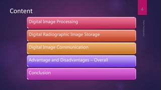
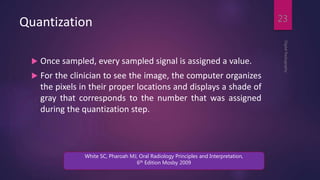
In digital imaging, a pixel [picture element] is the smallest
controllable element of a picture represented on the
screen
DigitalRadiography
14
[Internet] [cited 2014 Apr 10]. Available from
http://en.wikipedia.org/wiki/Pixel](https://image.slidesharecdn.com/0suqo7ptmclruea6sbvx-signature-7d026324264c1f55cdf36b88e78788580efb936718fbd8ad397e573d70e66131-poli-160402122754/85/Digital-imaging-IN-DENTISTRY-14-320.jpg)
![Pixel
DigitalRadiography
15
[Internet] [cited 2014 Apr 10]. Available from
http://en.wikipedia.org/wiki/Pixel](https://image.slidesharecdn.com/0suqo7ptmclruea6sbvx-signature-7d026324264c1f55cdf36b88e78788580efb936718fbd8ad397e573d70e66131-poli-160402122754/85/Digital-imaging-IN-DENTISTRY-15-320.jpg)
![Pixel
DigitalRadiography
16
[Internet] [cited 2014 Apr 10]. Available from
http://en.wikipedia.org/wiki/Pixel](https://image.slidesharecdn.com/0suqo7ptmclruea6sbvx-signature-7d026324264c1f55cdf36b88e78788580efb936718fbd8ad397e573d70e66131-poli-160402122754/85/Digital-imaging-IN-DENTISTRY-16-320.jpg)


![DigitalRadiography
40
[Internet] [cited 2014 Apr 10]. Available from
http://www.vikdhillon.staff.shef.ac.uk/teaching/phy217/detectors](https://image.slidesharecdn.com/0suqo7ptmclruea6sbvx-signature-7d026324264c1f55cdf36b88e78788580efb936718fbd8ad397e573d70e66131-poli-160402122754/85/Digital-imaging-IN-DENTISTRY-40-320.jpg)
![DigitalRadiography
41
[Internet] [cited 2014 Apr 10]. Available from
http://www.vikdhillon.staff.shef.ac.uk/teaching/phy217/detectors](https://image.slidesharecdn.com/0suqo7ptmclruea6sbvx-signature-7d026324264c1f55cdf36b88e78788580efb936718fbd8ad397e573d70e66131-poli-160402122754/85/Digital-imaging-IN-DENTISTRY-41-320.jpg)
![DigitalRadiography
42
[Internet] [cited 2014 Apr 10]. Available from
http://www.vikdhillon.staff.shef.ac.uk/teaching/phy217/detectors](https://image.slidesharecdn.com/0suqo7ptmclruea6sbvx-signature-7d026324264c1f55cdf36b88e78788580efb936718fbd8ad397e573d70e66131-poli-160402122754/85/Digital-imaging-IN-DENTISTRY-42-320.jpg)


![Scintillator
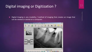
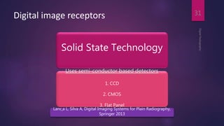
A scintillator is a material that exhibits scintillation — the
property of luminescence when excited by ionizing
radiation.
Luminescent materials, when struck by an incoming
particle, absorb its energy and scintillate, (i.e., re-emit the
absorbed energy in the form of light)
DigitalRadiography
58
[Internet] [cited 2014 Apr 10]. Available from
http://en.wikipedia.org/wiki/Scintillator](https://image.slidesharecdn.com/0suqo7ptmclruea6sbvx-signature-7d026324264c1f55cdf36b88e78788580efb936718fbd8ad397e573d70e66131-poli-160402122754/85/Digital-imaging-IN-DENTISTRY-58-320.jpg)


![Thin Film Transistor (TFT)
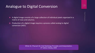
It is a special kind of field-effect transistor made by
depositing thin films of an active semiconductor layer
A transistor is a semiconductor device used to amplify and
switch electronic signals and electrical power. It is
composed of semiconductor material with at least three
terminals for connection to an external circuit.
DigitalRadiography
66
[Internet] [cited 2014 Apr 10]. Available from
http://en.wikipedia.org/wiki/Thin-film_transistor](https://image.slidesharecdn.com/0suqo7ptmclruea6sbvx-signature-7d026324264c1f55cdf36b88e78788580efb936718fbd8ad397e573d70e66131-poli-160402122754/85/Digital-imaging-IN-DENTISTRY-66-320.jpg)


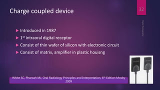
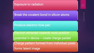
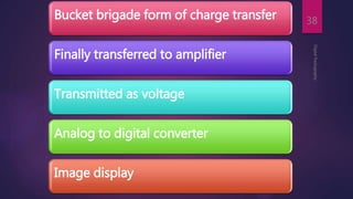
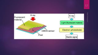
This document provides an overview of digital radiography. It begins with an introduction to the history and advantages of digital radiography compared to traditional film-based radiography. It then describes different types of digital image receptors including CCD, CMOS, flat panel detectors, and photostimulable phosphor plates. The document explains the process of analog to digital conversion and pixel formation. It provides details on the structure and functioning of different digital receptors. Advantages and disadvantages of each receptor type are also summarized.


