Downloaded 39 times
![A. Dilip Int. Journal of Engineering Research and Applications www.ijera.com
ISSN : 2248-9622, Vol. 4, Issue 9( Version 5), September 2014, pp.93-97
www.ijera.com 93 | P a g e
Design and Optimisation of Sae Mini Baja Chassis P. Anjani Devi*, A. Dilip** *(Department of Mechanical Engineering, Chaitanya Bharati Institute of technology, Hyderabad-75) ** (Department of Mechanical Engineering, Chaitanya Bharati Institute of technology, Hyderabad-75) ABSTRACT The objective is to design and develop the roll cage for All - Terrain Vehicle accordance with the rulebook of BAJA 2014 given by SAE. The frame of the SAE Baja vehicle needs to be lightweight and structurally sound to be competitive but still protect the driver. The vehicle needs to traverse all types of off-road conditions including large rocks, downed logs, mud holes, steep inclines, jumps and off camber turns. During the competition events there is significant risk of rollovers, falling from steep ledges, collisions with stationary objects, or impacts from other vehicles. Material for the roll cage is selected based on strength and availability. A software model is prepared in Pro-engineer. Later the design is tested against all modes of failure by conducting various simulations and stress analysis with the aid of ANSYS 13. Based on the result obtained from these tests the design is modified accordingly. A target of 2 is set for Yield Factor of Safety.
Keywords - SAE Baja vehicle, Factor of Safety, All Terrain Vehicle, Roll cage, Chasis
I. INTRODUCTION A chassis consists of an internal framework that supports a man-made object in its construction and use. It is analogous to an animal’s skeleton. If the running gear such as wheels and transmission, and sometimes even the driver's seat, are included then the assembly is described as a rolling chassis. The Mini-Baja Vehicle is an off-road race vehicle powered by a small gasoline engine. As is such the combination frame and roll cage must be equally strong and light. In an effort to fulfill the rules set down by the governing body and ensure proper integration, strength, and weight minimization; it is imperative to properly analyze the material properties and geometry as well as the overall design geometry. Types of Impact Tests: Front collision test, rear impact test, side impact test and roll over impact test . The vehicle in the track could hit a stationary object travelling at a speed of 30-40mph.The model is analyzed by applying the loads. The front collision test simulates the vehicle hitting a solid, immovable object at a speed of 35 mph . This is the maximum top speed the vehicle is expected to reach. The rear impact test simulates the vehicle being rear-ended by another 500 lb Baja vehicle, again at a speed of 35 mph. To make this test as hard as possible, the front of the vehicle is resting against a solid wall. The side impact test is identical to the rear impact, but the vehicle is oriented sideways relative to the motion of the incoming 500lb vehicle. Roll over impact simulates the vehicle rolled on its side.
II. DESIGN AND DEVELOPMENT
2.1 Material Selection As per the constraints given in the rulebook[1], the roll cage material must have at least 0.18% carbon content. The following materials which are commercially available and are currently being used for the roll cage of an ATV are shortlisted. A comparative study of these shortlisted materials is done on the basis of strength, availability and cost. The shortlisted materials are as follows. Table 2.1: Material Properties
AISI 1018 steel
AISI 1026 steel
AISI 4130 alloy steel
Density (g/cc)
7.87
7.85
7.85
Poisson’s ratio
0.29
0.27-0.30
0.27-0.30
YoungsModulus (GPa)
205
190- 210
190-210
Carbon content ( %)
0.14- 0.2
0.22-0.28
0.28-0.33
Tensile strength , Yield (MPa)
370
415
460
2.2 Material Requirements The materials used in the cage must meet certain requirements of geometry as set by SAE, and other limitations. As the frame is used in a racing vehicle, weight is a crucial factor and must be considered. The proper balance of fulfilling the design requirements and minimizing the weight is crucial to a successful design.
RESEARCH ARTICLE OPEN ACCESS](https://image.slidesharecdn.com/p49059397-141021035303-conversion-gate02/85/Design-and-Optimisation-of-Sae-Mini-Baja-Chassis-1-320.jpg)
![A. Dilip Int. Journal of Engineering Research and Applications www.ijera.com
ISSN : 2248-9622, Vol. 4, Issue 9( Version 5), September 2014, pp.93-97
www.ijera.com 93 | P a g e
Design and Optimisation of Sae Mini Baja Chassis P. Anjani Devi*, A. Dilip** *(Department of Mechanical Engineering, Chaitanya Bharati Institute of technology, Hyderabad-75) ** (Department of Mechanical Engineering, Chaitanya Bharati Institute of technology, Hyderabad-75) ABSTRACT The objective is to design and develop the roll cage for All - Terrain Vehicle accordance with the rulebook of BAJA 2014 given by SAE. The frame of the SAE Baja vehicle needs to be lightweight and structurally sound to be competitive but still protect the driver. The vehicle needs to traverse all types of off-road conditions including large rocks, downed logs, mud holes, steep inclines, jumps and off camber turns. During the competition events there is significant risk of rollovers, falling from steep ledges, collisions with stationary objects, or impacts from other vehicles. Material for the roll cage is selected based on strength and availability. A software model is prepared in Pro-engineer. Later the design is tested against all modes of failure by conducting various simulations and stress analysis with the aid of ANSYS 13. Based on the result obtained from these tests the design is modified accordingly. A target of 2 is set for Yield Factor of Safety.
Keywords - SAE Baja vehicle, Factor of Safety, All Terrain Vehicle, Roll cage, Chasis
I. INTRODUCTION A chassis consists of an internal framework that supports a man-made object in its construction and use. It is analogous to an animal’s skeleton. If the running gear such as wheels and transmission, and sometimes even the driver's seat, are included then the assembly is described as a rolling chassis. The Mini-Baja Vehicle is an off-road race vehicle powered by a small gasoline engine. As is such the combination frame and roll cage must be equally strong and light. In an effort to fulfill the rules set down by the governing body and ensure proper integration, strength, and weight minimization; it is imperative to properly analyze the material properties and geometry as well as the overall design geometry. Types of Impact Tests: Front collision test, rear impact test, side impact test and roll over impact test . The vehicle in the track could hit a stationary object travelling at a speed of 30-40mph.The model is analyzed by applying the loads. The front collision test simulates the vehicle hitting a solid, immovable object at a speed of 35 mph . This is the maximum top speed the vehicle is expected to reach. The rear impact test simulates the vehicle being rear-ended by another 500 lb Baja vehicle, again at a speed of 35 mph. To make this test as hard as possible, the front of the vehicle is resting against a solid wall. The side impact test is identical to the rear impact, but the vehicle is oriented sideways relative to the motion of the incoming 500lb vehicle. Roll over impact simulates the vehicle rolled on its side.
II. DESIGN AND DEVELOPMENT
2.1 Material Selection As per the constraints given in the rulebook[1], the roll cage material must have at least 0.18% carbon content. The following materials which are commercially available and are currently being used for the roll cage of an ATV are shortlisted. A comparative study of these shortlisted materials is done on the basis of strength, availability and cost. The shortlisted materials are as follows. Table 2.1: Material Properties
AISI 1018 steel
AISI 1026 steel
AISI 4130 alloy steel
Density (g/cc)
7.87
7.85
7.85
Poisson’s ratio
0.29
0.27-0.30
0.27-0.30
YoungsModulus (GPa)
205
190- 210
190-210
Carbon content ( %)
0.14- 0.2
0.22-0.28
0.28-0.33
Tensile strength , Yield (MPa)
370
415
460
2.2 Material Requirements The materials used in the cage must meet certain requirements of geometry as set by SAE, and other limitations. As the frame is used in a racing vehicle, weight is a crucial factor and must be considered. The proper balance of fulfilling the design requirements and minimizing the weight is crucial to a successful design.
RESEARCH ARTICLE OPEN ACCESS](https://image.slidesharecdn.com/p49059397-141021035303-conversion-gate02/75/Design-and-Optimisation-of-Sae-Mini-Baja-Chassis-1-2048.jpg)
![A. Dilip Int. Journal of Engineering Research and Applications www.ijera.com
ISSN : 2248-9622, Vol. 4, Issue 9( Version 5), September 2014, pp.93-97
www.ijera.com 94 | P a g e
The rules define the cage to be made with materials equivalent to the following specification Steel members with at least equal bending stiffness and bending strength to 1018 steel having a circular cross section having a 25.4 mm (1 inch) OD and a wall thickness of 3 mm (0.120 in.)[1]A key factor of this statement is those only steel members are allowed for the frames construction. However the alloy of the steel is definable by the competitor as long as it meets the equivalency requirements. These values are required to be calculated about the axis that gives the lowest value. Calculating the strength and stiffness this way ensures that tubes with a non- circular cross-section will be equivalent even in a worst case loading situation. The rules go on further to define bending strength and stiffness by: Bending stiffness is proportional to the EI product and bending strength is given by the value of SyI/c, (for 1018 steel the values are; Sy= 370Mpa (53.7ksi) E=205GPa (29,700 ksi). E = the modulus of elasticity I = the second moment of area for the cross section about the (inch4) axis giving the lowest value I = π(Do4 - Di4)/64 Sy = the yield strength of material (psi) c = the distance from the neutral axis to the extreme fiber Table 2.2: Bending stiffness Vs Wall thickness Table 2.3: Bending strength Vs Wall thickness
After reviewing each of these analyses it is evident that the best choice would be use 4130 Chromoly tubing with a 1.125 inch diameter and a 0.083 inch wall thickness.
2.3 GEOMETRY CREATION The design was made using the Pro-engineer software package. The model was made fully parametric. This means the features of the model are based upon those preceding it, and will change according to any modifications to the parent features. The usage of parametric design was extremely important with this design. As so many factors interact in the design of the frame, the parametric properties allowed the change of a single part to automatically change the design of all parts interacting with it.
III. ANALYSIS
The next stage in the design process is to analyze the frame and add features accordingly. There were a few features of the design that might need some additional strengthening. For these reasons it was deemed that there should be an analysis of front impact, side impact, rollover impact, and the loading on the frame from the front shocks. However before these analyses are performed an examination of the loading forces exerted on the vehicle must be completed. The finite element analysis software program used for this project was ANSYS.
PIPE16 is a uniaxial element with tension- compression, torsion, and bending capabilities. The element has six degrees of freedom at two nodes: translations in the nodal x, y, and z directions and rotations about the nodal x, y, and z axes. This element is based on the three-dimensional beam element (BEAM4), and includes simplifications due to its symmetry and standard pipe geometry. Total number of elements = 6305 Total number of Nodes = 6276
3.1 FRONTAL IMPACT The first analysis to be completed was that of a front collision with a stationary object. In this case a deceleration of 10 G’s was the assumed loading. The model is supposed to make contact at its front junctions where FBM (Front Bracing Members ) SIM(Side Impact Members) and LFS(Lower Frame Side)members join. So the loads act horizontally in positive X direction on this points. 3.1.2 Boundary conditions Calculation of frontal impact force = M * 10*9.8 Mass = 320 kg (combined weight of vehicle and occupant) Load=31360 N](https://image.slidesharecdn.com/p49059397-141021035303-conversion-gate02/85/Design-and-Optimisation-of-Sae-Mini-Baja-Chassis-2-320.jpg)
![A. Dilip Int. Journal of Engineering Research and Applications www.ijera.com
ISSN : 2248-9622, Vol. 4, Issue 9( Version 5), September 2014, pp.93-97
www.ijera.com 97 | P a g e
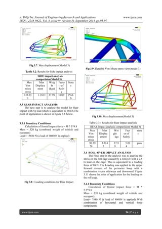
Fig 3.11: Loading conditions for roll over impact Fig 3.12: Detailed Von-Mises stress view(model 3) Fig 3.13: Detailed Von mises stress view (model 4) Table 3.4: Results for Roll-Over impact analysis
Fig 3.14: Detailed Von-mises stress view (model 5)
IV. RESULTS AND DISCUSSIONS
The modifications approved as per Roll over impact would also affect for Frontal,Side as well as Rear Impact. The final model is thus carried out for analysis of frontal, side and rear impacts to determine their respective vonmises stress and maximum displacements. The final results obtained are show in the Table 3.5. Table 3.5 :Final Results
V. Conclusion
The usage of finite element analysis was invaluable to the design and analysis of the frame. The analysis allowed the addition of important and key structural components to help the vehicle with stand front, side impacts as well as the rear impacts. While a viable solution to the stresses seen in a rollover type impact could not be found due to the set design constraints, the finite element analysis gave a very accurate prediction of where failure would occur in this situation.
REFERENCES
[1] Rulebook BAJA SAE INTERNATIONAL 2014. [2] Chris Bennett, Eric Lockwood, Anthony McClinton, Robin McRee and Colin Pemberton “SAE Mini Baja Frame Analysis”. [3] MohdHanif Mat*, Amir Radzi Ab. Ghani “Design and Analysis of ‘Eco’ Car Chassis”,International Symposium on Robotics and Intelligent Sensors 2012 (IRIS 2012) [4] Elert, Glenn. “Acceleration That Would Kill a Human,”http://hypertextbook.com/facts/ 2004/YuriyRafailov.shtml [5] http://users.tpg.com.au/users/mpaine/rollov er.html
Type of Impact
Initial model’s factor of safety
Optimised model’s Factor of safety
Status
Frontal
0.832
2.322
PASS
Side Impact
2.003
2.247
PASS
Rear mpact
1.878
4.336
PASS
Roll-Over
0.762
1.8517
FAIL
ROLL impact analysis comparision
Max Von mises stress
Max Displacement
Weight kgs
Factor of Safety
status
Model 3
364.585
12.962
37.99
1.2617
Fail
Model 4
352.416
11.6629
39.6
1.3052
Fail
Model 5
248.42
10.3933
39.99
1.8517
Fail](https://image.slidesharecdn.com/p49059397-141021035303-conversion-gate02/85/Design-and-Optimisation-of-Sae-Mini-Baja-Chassis-5-320.jpg)

The document details the design and optimization of a roll cage for an SAE Mini Baja chassis aimed at ensuring driver safety while minimizing weight for competitive performance. It outlines the material selection process, design methodology using software like Pro-Engineer and ANSYS for simulations, and impact tests for various load scenarios. The final analysis demonstrates the effectiveness of the design through stress and displacement results, while highlighting the need for improvements in rollover impact resistance.