Downloaded 173 times


![V
CHAPTER 8
COMPOSITE AND PROPERTIES 24
8.1 COMPOSITE 24
8.2 PROPERTIES OF COMPOSITE 28
8.3 METHADOLOGY 29
CHAPTER 9
WEIGHT CALCULATION 30
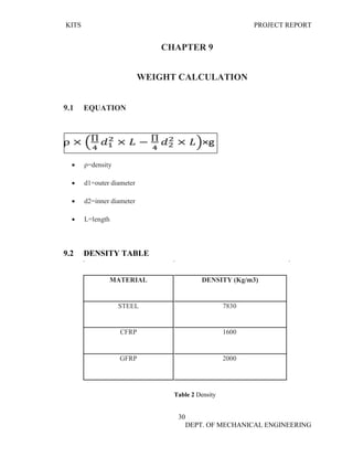
9.1 EQUATION 30
9.2 DENSITY TABLE 30
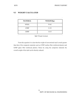
9.3 WEIGHT CALCULATED 31
CHAPTER 10
ANALYSIS 32
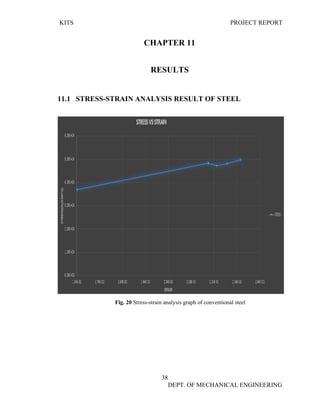
10.1 CONVENTIONAL STEEL [STRESS ANALYSIS] 32
10.2 CONVENTIONAL STEEL [STRAIN ANALYSIS] 33
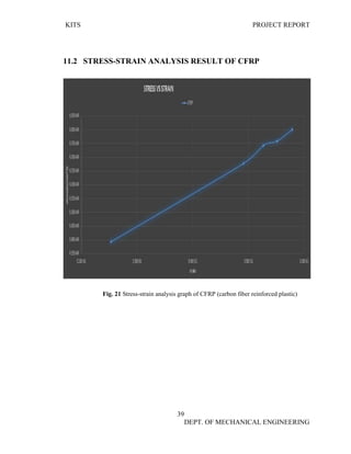
10.3 CFRP [STRESS ANALYSIS] 33
10.4 CFRP [STRAIN ANALYSIS] 34
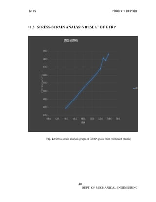
10.5 GFRP [STRESS ANALYSIS] 34
10.6 GFRP [STRAIN ANALYSIS] 35
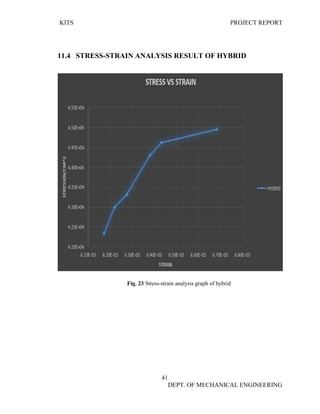
10.7 HYBRID [STRESS ANALYSIS] 36
10.8 HYBRID [STRAIN ANALYSIS] 36](https://image.slidesharecdn.com/fullprojectreport-180608081312/85/DESIGN-AND-ANALYSIS-OF-COMPOSITE-PROPELLER-DRIVEN-SHAFT-USING-FEA-7-320.jpg)
![KITS PROJECT REPORT
32
DEPT. OF MECHANICAL ENGINEERING
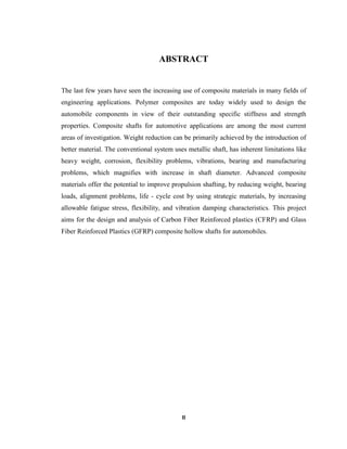
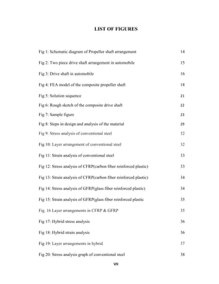
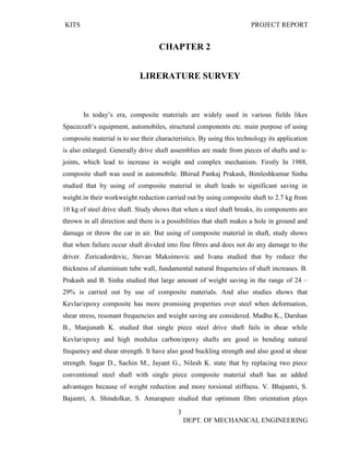
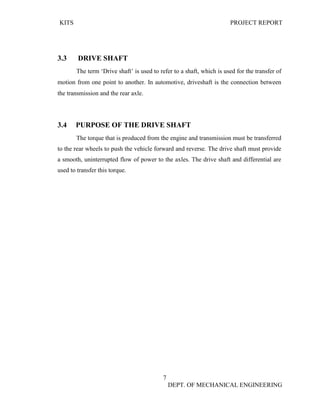
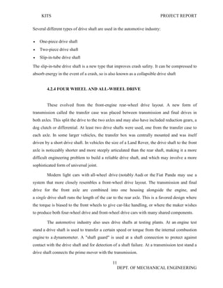
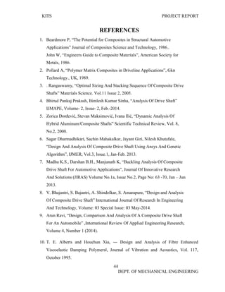
CHAPTER 10
ANALYSIS
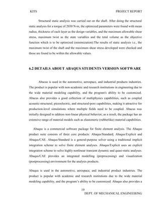
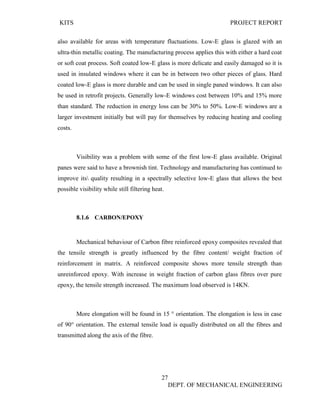
Analysis is done with the help of abacus software and the following are the analysis results;
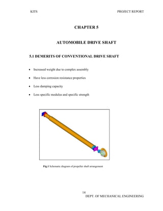
10.1 CONVENTIONAL STEEL [STRESS ANALYSIS]
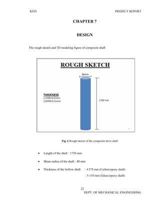
Fig. 9 Stress analysis of conventional steel
Fig. 10 Layer arrangement of conventional steel](https://image.slidesharecdn.com/fullprojectreport-180608081312/85/DESIGN-AND-ANALYSIS-OF-COMPOSITE-PROPELLER-DRIVEN-SHAFT-USING-FEA-42-320.jpg)
![KITS PROJECT REPORT
33
DEPT. OF MECHANICAL ENGINEERING
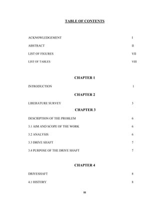
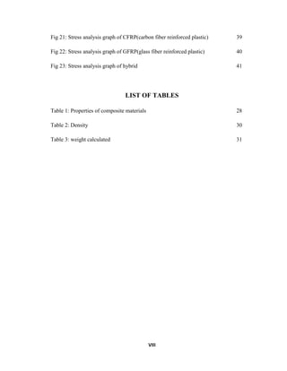
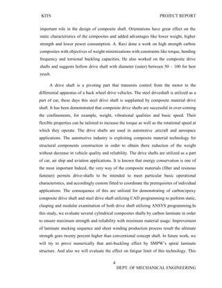
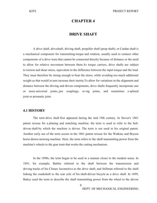
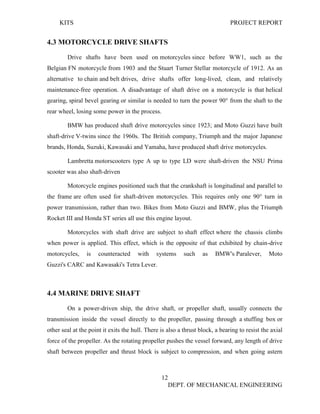
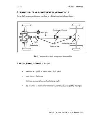
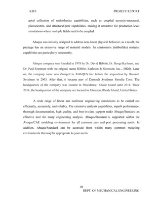
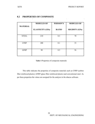
10.2 CONVENTIONAL STEEL [STRAIN ANALYSIS]
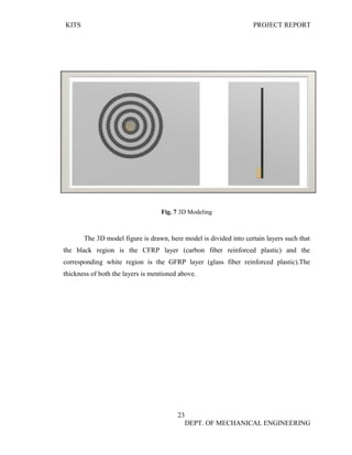
Fig. 11 Strain analysis of conventional steel
10.3 CFRP [STRESS ANALYSIS]
Fig. 12 Stress analysis of CFRP (carbon fiber reinforced plastic)](https://image.slidesharecdn.com/fullprojectreport-180608081312/85/DESIGN-AND-ANALYSIS-OF-COMPOSITE-PROPELLER-DRIVEN-SHAFT-USING-FEA-43-320.jpg)
![KITS PROJECT REPORT
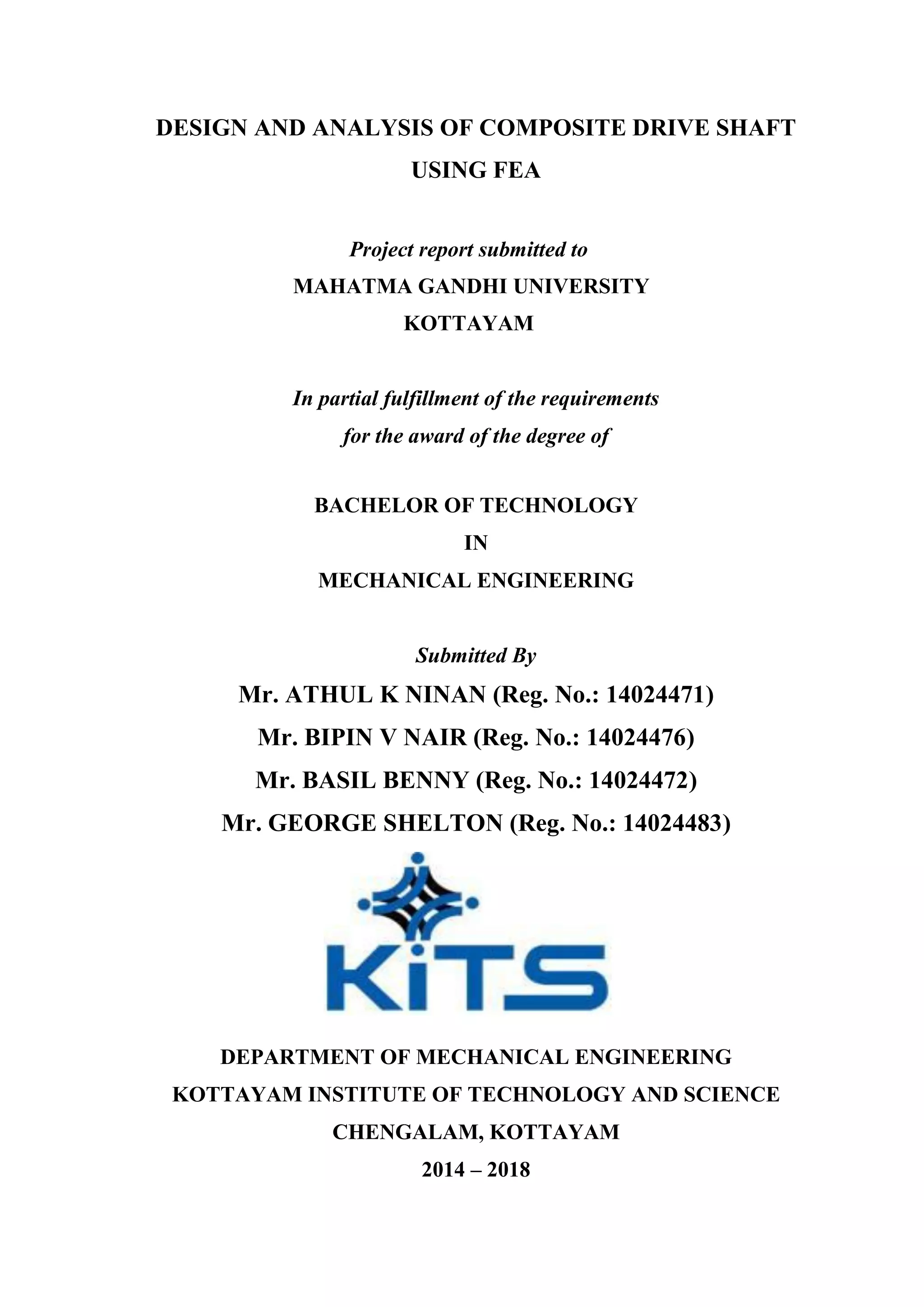
34
DEPT. OF MECHANICAL ENGINEERING
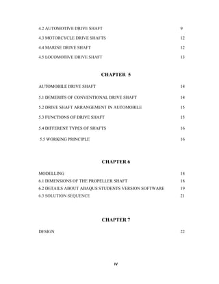
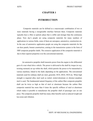
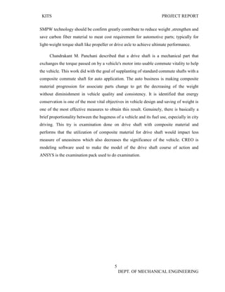
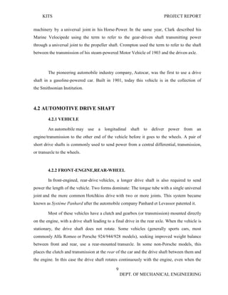
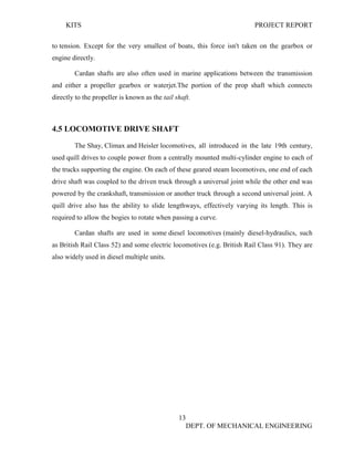
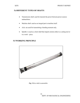
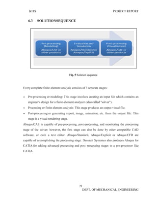
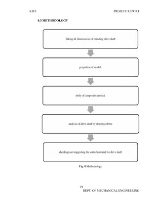
10.4 CFRP [STRAIN ANALYSIS]
‘
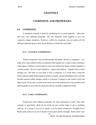
Fig. 13 Strain analysis of CFRP (carbon fiber reinforced plastic)
10.5 GFRP [STRESS ANALYSIS]
Fig. 14 Stress analysis of GFRP (glass fiber reinforced plastic)](https://image.slidesharecdn.com/fullprojectreport-180608081312/85/DESIGN-AND-ANALYSIS-OF-COMPOSITE-PROPELLER-DRIVEN-SHAFT-USING-FEA-44-320.jpg)
![KITS PROJECT REPORT
35
DEPT. OF MECHANICAL ENGINEERING
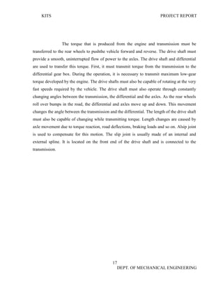
10.6 GFRP [STRAIN ANALYSIS]
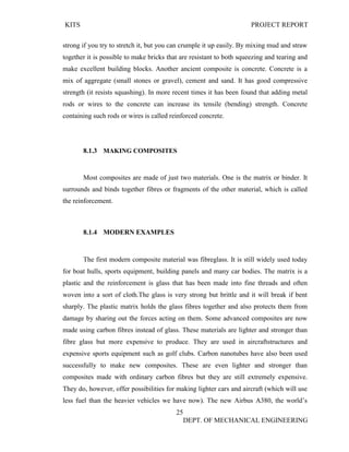
Fig. 15 Strain analysis of GFRP (glass fiber reinforced plastic)
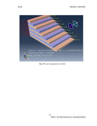
Fig. 16 Layer arrangements in CFRP & GFRP](https://image.slidesharecdn.com/fullprojectreport-180608081312/85/DESIGN-AND-ANALYSIS-OF-COMPOSITE-PROPELLER-DRIVEN-SHAFT-USING-FEA-45-320.jpg)
![KITS PROJECT REPORT
36
DEPT. OF MECHANICAL ENGINEERING
10.7 HYBRID [STRESS ANALYSIS]
Fig. 17 Hybrid stress analysis
10.8 HYBRID [STRAIN ANALYSIS]
Fig. 18 Hybrid strain analysis](https://image.slidesharecdn.com/fullprojectreport-180608081312/85/DESIGN-AND-ANALYSIS-OF-COMPOSITE-PROPELLER-DRIVEN-SHAFT-USING-FEA-46-320.jpg)

The document is a project report on the design and analysis of composite drive shafts using finite element analysis (FEA) submitted by students for their Bachelor's degree in Mechanical Engineering. It discusses the advantages of using composite materials, particularly carbon fiber reinforced plastics (CFRP) and glass fiber reinforced plastics (GFRP), in automotive applications due to their lower weight and improved mechanical properties compared to conventional metallic shafts. The report includes various chapters detailing the background, analysis, methodology, results, and future scope of the project.