Downloaded 21 times
![IOSR Journal of Mechanical and Civil Engineering (IOSR-JMCE)
e-ISSN: 2278-1684 Volume 6, Issue 1 (Mar. - Apr. 2013), PP 44-49
www.iosrjournals.org
www.iosrjournals.org 44 | Page
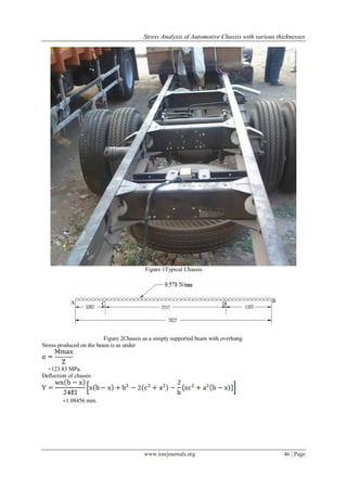
Stress Analysis of Automotive Chassis with Various Thicknesses
Hemant B.Patil1
, Sharad D.Kachave2
, Eknath R.Deore3
1
(P.G.Student Mechanical, S.SV.P.S.B.S.D.C.O.Engg, Dhule North Maharashtra University, India)
2
(Mechanical, S.SV.P.S.B.S.D.C.O.Engg, Dhule North Maharashtra University, India)
3
(Head of Mechanical, S.SV.P.S.B.S.D.C.O.Engg, Dhule North Maharashtra University, India)
Abstract : This paper presents, stress analysis of a ladder type low loader truck chassis structure consisting of
C-beams design for application of 7.5 tonne was performed by using FEM. The commercial finite element
package CATIA version 5 was used for the solution of the problem. To reduce the expenses of the chassis of the
trucks, the chassis structure design should be changed or the thickness should be decreased. Also determination
of the stresses of a truck chassis before manufacturing is important due to the design improvement. In order to
achieve a reduction in the magnitude of stress at critical point of the chassis frame, side member thickness,
cross member thickness and position of cross member from rear end were varied. Numerical results showed that
if the thickness change is not possible, changing the position of cross member may be a good alternative.
Computed results are then compared to analytical calculation, where it is found that the maximum deflection
agrees well with theoretical approximation but varies on the magnitude aspect.
Keywords - Stress analysis, fatigue life prediction and finite element method etc.
I. INTRODUCTION
The chassis of trucks is the backbone of vehicles and integrates the main component systems such as
the axles, suspension, power train, cab and trailer, and is usually subjected to the weight of cabin, its content,
and inertia forces arising due to roughness of road surfaces etc. (i.e. static, dynamic and cyclic loading). The
stress analysis is important in fatigue study and life prediction of components to determine the highest stress
point commonly known as critical point which initiates to probable failure, this critical point is one of the factors
that may cause the fatigue failure. The magnitude of the stress can be used to predict the life span of the chassis.
The location of critical stress point is thus important so that the mounting of the components like engine,
suspension, transmission and more can be determined and optimized, Finite Element Method (FEM) is one of
the method to locate the critical point [1,2]. Safety factor is used to provide a design margin over the theoretical
design capacity. This allows consolidation of uncertainties in the design process [3].Jadav Chetan S. et al
reviews various factors affecting the fatigue life of an structure like cyclic stress state, geometry, surface quality,
material type, residual stresses, size and distribution of internal defects, direction of loading & grain size [4].
In this study, chassis structures are comparing by the thicknesses of the profiles. For determining the
strength of the frame, structural analyses were performed for these frames of thicknesses of 4, 5, 6 mm and also
changing the position of cross member and change the thickness of cross member near high stress zone. The
truck chassis was modeled and the finite element analyses were solved in CATIA V5R10.
During this five different cases consider to study the effect of thickness on chassis stresses
Case 1 Thickness of Side member is 4 mm.
Case 2 Thickness of Side member is 5 mm.
Case 3 Thickness of Side member is 6 mm.
Case 4 Change position of 4th
Cross member at 2520 from rear end.
Case 5 Thickness of 5th
Cross member is 5 mm.
II. LITERATURE REVIEW
Roslan Abd Rahman et al [1] does stress analysis of heavy duty truck chassis by utilizing a commercial
finite element package ABAQUS. To determine critical point so that by design modifications the stresses can be
reduces to improve the fatigue life of components. During this he uses ASTM low alloy steel a 710 C (Class 3)
with 552 MPa of yield strength and 620 MPa of tensile strength for chassis founds the maximum stress 386.9
MPa at critical point occurred at opening of chassis This critical point is located at element 86104 and node
16045, which is in contacted with the bolt from this he concludes that this critical point is an initial to probable
failure.
Cicek Karaoglu et al [2] does stress analysis of heavy duty truck chassis with riveted joints by utilizing
a commercial finite element package ANSYS version 5.3.during this study, he examine the effect of the side
member thickness and connection plate thickness with length change, the side member thickness is varied from
8 to 12 mm, and the thickness of the connection plate is also varied from 8 to 12 mm by local plate, the](https://image.slidesharecdn.com/g0614449-150114223233-conversion-gate01/85/Stress-Analysis-of-Automotive-Chassis-with-Various-Thicknesses-1-320.jpg)
![Stress Analysis of Automotive Chassis with various thicknesses
www.iosrjournals.org 45 | Page
connection plate thickness is varied from 7 to 10 mm, and the length of the connection plate (L) is varied from
390 to 430 mm. from this he concluded that if the change of the side member thickness using local plates is not
possible, due to increase weight of chassis then choosing an optimum connection plate length (L) seems to be
best practical solutions for decreasing the stress values.
Mohd Azizi Muhammad Nor et al [3] performs the stress analysis of an actual low loader structure
consisting of I-beams design application of 35 tonne trailer. He uses modeling software CATIA V5R18. The
results of analysis revealed that the location maximum deflection and maximum stress agrees well with
theoretical maximum location of simple beam under uniform loading distribution. This study found out that
there is discrepancy between the theoretical (2-D) and numerical (3-D FEA) results. It is observed that the
maximum deflection is pointed in situated in between BC1 and BC2 with magnitude of 7.79mm. The results of
the numerical analysis revealed that the location maximum deflection and maximum stress agrees well with
theoretical maximum location of simple beam loaded by uniform force.
Jadav Chetan S et al [4] review the investigations that have been made on the different fatigue analysis
techniques of automobile frames.
N.K.Ingole et al [5] does the modifications in existing model of tractor trailer chassis by 1) Variation in
Cross sectional areas of cross members, 2) Variation in cross sectional areas of cross and longitudinal members,
3) Variation in cross sectional areas of cross and longitudinal members and 4) Changing the position of cross
members of main frames of chassis, Considering variable cross sectional areas of cross and longitudinal
members. It has been found that, maximum stress present in existing chassis is 75 MPa and weight of chassis is
751.82 kg. Case 4 leads to maximum weight reduction of approx 112 kg as compared to case 1, 2 and 3. So
modifications as per case 4 are also recommended, case 3 the weight reduction is 88 kg with maximum stress
level in range of 25MPa to 66 MPa.
III. BASIC CALCULATION FOR CHASSIS FRAME
For Case 1
Model No. = 10.75 (Eicher)
Side bar of the chassis are made from “C” Channels with 200mm x 55 mm x 5 mm
Front Overhang (a) = 1005 mm.
Rear Overhang (c) = 1305 mm.
Wheel Base (b) = 3515 mm. Material of the chassis is Steel
Table 1Material properties of the Truck Chassis Steel
Young’s Modulus 200 GPa.
Poisson’s Ratio 0.266.
Density 7860 Kg/m3
.
Yield Strength 250 MPa.
Symmetry Linear Isotropic.
Capacity of Truck = 7.5 ton = 7500 kg = 73575 N.
Capacity of Truck with 1.25% = 9375 N = 91968.75 N.
Weight of the body and engine = 2 ton = 2000 kg = 19620 N
Total load acting on chassis = Capacity of the Chassis + Weight of body and engine
= 91968.75 + 19620
= 111588.75 N
Chassis has two beams. So load acting on each beam is half of the Total load acting on the chassis. Load acting
on the single frame =111588.75/2 = 55794.375 N / Beam.
Uniformly Distributed Load is 55794.375 / 5825 =9.578 N/mm.](https://image.slidesharecdn.com/g0614449-150114223233-conversion-gate01/85/Stress-Analysis-of-Automotive-Chassis-with-Various-Thicknesses-2-320.jpg)


![Stress Analysis of Automotive Chassis with various thicknesses
www.iosrjournals.org 49 | Page
Comparing case 5 with case 2 only by increasing thickness of cross member weight is increases by 2.92 Kg
stresses are decreased by 43.8 N/mm2
, and displacement is increased by 0.022mm.
Comparing case 4 with case 2 only by changing the position of cross member weight is not affecting
stresses are deceases by 06.7 N/mm2
, and displacement is increased by 0.026 mm.
Comparing case 3 with case 2 only by increasing 23.58 Kg stresses are increased by 06.5 N/mm2
, and
displacement is increased by 0.024mm.
Hence it is better to change the thickness of cross member at critical stress point than changing the thickness of
side member and position of chassis for reduction in stress values and deflection of chassis.
Acknowledgment
I express my deep sense of gratitude and Special thanks to Eicher Co. Ltd. authorized show-room &
service center Siddhi Motors Pvt. Ltd., Dhule, for giving me training and required data.
REFERENCES
[1] Roslan Abd Rahman, Mohd Nasir Tamin, Ojo Kurdi “Stress analysis of heavy duty truck chassis as a preliminary data for its fatigue
life prediction using FEM” Jurnal Mekanikal December 2008, No. 26, 76 – 85.
[2] Cicek Karaoglu, N. Sefa Kuralay “Stress analysis of a truck chassis with riveted joints” Elsevier Science B.V Finite Elements in
Analysis and Design 38 (2002) 1115–1130.
[3] Mohd Azizi Muhammad Nora,, Helmi Rashida, Wan Mohd Faizul Wan Mahyuddin “Stress Analysis of a Low Loader Chassis”
Elsevier Ltd. Sci Verse Science Direct Procedia Engineering 41 ( 2012 ) 995 – 1001.
[4] Jadav Chetan S., Panchal Khushbu C., Patel Fajalhusen “A Review of the Fatigue Analysis of an Automobile Frames” International
Journal of Advanced Computer Research, Volume-2 Number-4 Issue-6 December-2012, (ISSN (print): 2249-7277 ISSN (online):
2277-7970).
[5] N.K.Ingole, D.V. Bhope “Stress analysis of tractor trailer chassis for self weight reduction” International Journal of Engineering
Science and Technology (IJEST), ISSN: 0975-5462 Vol. 3 No. 9 September 2011.
[6] I. Kutay Yilmazcoban, Yaşar Kahraman “Truck chassis structural thickness optimization with the help of finite element technique”
TOJSAT the Online Journal of Science and Technology - Volume 1, Issue 3, July 2011.
[7] Patel Vijay kumar V, Prof. R. I. Patel “Structural Analysis of Automotive Chassis Frame and Design Modification for Weight
Reduction” International Journal of Engineering Research & Technology (IJERT), ISSN: 2278-0181, Vol. 1 Issue 3, May – 2012.
[8] Beam formula with shear and moment diagram, American forest and paper association, Inc, American Wood Council, 1111 19th
St., NW. Suite 800, Washington. DC 20036, 202 – 463 – 4713.](https://image.slidesharecdn.com/g0614449-150114223233-conversion-gate01/85/Stress-Analysis-of-Automotive-Chassis-with-Various-Thicknesses-6-320.jpg)

The document discusses the stress analysis of a ladder type low loader truck chassis using finite element method (FEM) to determine the effects of varying thicknesses and positions of cross members on stress distribution. It presents various cases with different member thicknesses and cross member placements, revealing that modifying cross member thickness is more effective in reducing stress than changing side member thickness. Numerical results generally align with theoretical analyses, showing that optimal design modifications can improve chassis performance while reducing weight.


![[IJET V2I5P14] Authors: Miss Kirti. S. Kakade, Prof. P. A. Narwade](https://cdn.slidesharecdn.com/ss_thumbnails/ijet-v2i5p14-161107142948-thumbnail.jpg?width=640&height=640&fit=bounds)


