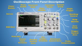
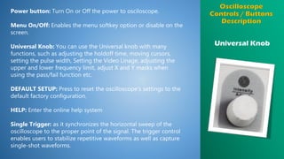
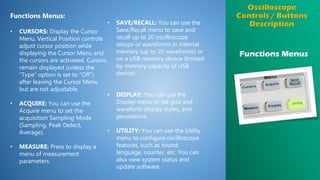
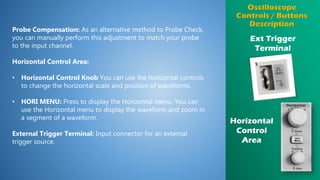
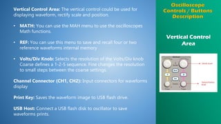
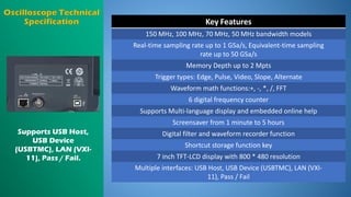
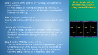
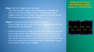
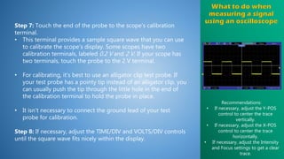
Electrónica
Analógica
Eduardo Emanuel Tovias Garza
Engineer Aurelio García
Técnico
Mecatrónica Área
Automatización
4th June 2020 - Matamoros,
Tamaulipas
Power button: Turn On or Off the power to osciloscope.
Menu On/Off: Enables the menu softkey option or disable on the
screen.
Universal Knob: You can use the Universal knob with many
functions, such as adjusting the holdoff time, moving cursors,
setting the pulse width, Setting the Video Linage, adjusting the
upper and lower frequency limit, adjust X and Y masks when
using the pass/fail function etc.
DEFAULT SETUP: Press to reset the oscilloscope’s settings to the
default factory configuration.
HELP: Enter the online help system
Single Trigger: as it synchronizes the horizontal sweep of the
oscilloscope to the proper point of the signal. The trigger control
enables users to stabilize repetitive waveforms as well as capture
single-shot waveforms.
Universal Knob
Functions Menus:
• CURSORS: Display the Cursor
Menu. Vertical Position controls
adjust cursor position while
displaying the Cursor Menu and
the cursors are activated. Cursors
remain displayed (unless the
“Type” option is set to “Off”)
after leaving the Cursor Menu
but are not adjustable.
• ACQUIRE: You can use the
Acquire menu to set the
acquisition Sampling Mode
(Sampling, Peak Detect,
Average).
• MEASURE: Press to display a
menu of measurement
parameters.
• SAVE/RECALL: You can use the
Save/Recall menu to save and
recall up to 20 oscilloscope
setups or waveforms in internal
memory (up to 20 waveforms) or
on a USB memory device (limited
by memory capacity of USB
device).
• DISPLAY: You can use the
Display menu to set grid and
waveform display styles, and
persistence.
• UTILITY: You can use the Utility
menu to configure oscilloscope
features, such as sound,
language, counter, etc. You can
also view system status and
update software.
Functions Menus
Trigger Control
Area
RUN/STOP: Continuously acquires waveforms or stops the
acquisition.
Auto: The oscilloscope is in auto mode and is acquiring
waveforms in the absence of triggers.
Trigger Control Area:
• TRIG MENU: You can use the Trigger menu to set the trigger
type (Edge. Pulse, Video, Slope, Alternative) and trigger
settings.
• SET TO 50%: Press to stabilize a waveform quickly. The
oscilloscope can set the trigger level to be halfway between
the minimum and maximum voltage level automatically. This is
useful when you connect a signal to the EXT TRIG connector
and set the trigger source to Ext or Ext/5.
• FORCE: Use the FORCE button to complete the current
waveform acquisition whether the oscilloscope detects a
trigger or not. This is useful for Single acquisitions and Normal
trigger mode.
Ext Trigger
Terminal
Probe Compensation: As an alternative method to Probe Check,
you can manually perform this adjustment to match your probe
to the input channel.
Horizontal Control Area:
• Horizontal Control Knob You can use the horizontal controls
to change the horizontal scale and position of waveforms.
• HORI MENU: Press to display the Horizontal menu. You can
use the Horizontal menu to display the waveform and zoom in
a segment of a waveform.
External Trigger Terminal: Input connector for an external
trigger source.
Horizontal
Control
Area
Vertical Control
Area
Vertical Control Area: The vertical control could be used for
displaying waveform, rectify scale and position.
• MATH: You can use the MAH menu to use the oscilloscopes
Math functions.
• REF: You can use this menu to save and recall four or two
reference waveforms internal memory
• Volts/Div Knob: Selects the resolution of the Volts/Div knob
Coarse defines a 1-2-5 sequence. Fine changes the resolution
to small steps between the coarse settings.
Channel Connector (CH1, CH2): Input connectors for waveforms
display
Print Key: Saves the waveform image to USB flash drive.
USB Host: Connect a USB flash disk to oscillator to save
waveforms prints.
Key Features
150 MHz, 100 MHz, 70 MHz, 50 MHz bandwidth models
Real-time sampling rate up to 1 GSa/s, Equivalent-time sampling
rate up to 50 GSa/s
Memory Depth up to 2 Mpts
Trigger types: Edge, Pulse, Video, Slope, Alternate
Waveform math functions:+, -, *, /, FFT
6 digital frequency counter
Supports Multi-language display and embedded online help
Screensaver from 1 minute to 5 hours
Digital filter and waveform recorder function
Shortcut storage function key
7 inch TFT-LCD display with 800 * 480 resolution
Multiple interfaces: USB Host, USB Device (USBTMC), LAN (VXI-
11), Pass / Fail
Supports USB Host,
USB Device
(USBTMC), LAN (VXI-
11), Pass / Fail.
Specifications
Bandwidth 100MHz
Sampling Rate 1 GSa/s
Rise Time Typical 3.5 ns
Channel Count 2 + EXT
Maximum Input Voltage 400 V , 1 MΩ
Resolution 8-bit
Vertical Sensitivy 2 mV/div - 10 V/div
Time Base 1 GSa/s - 50 GSa/s
Input Impedance
(1 MΩ±2%)||(18 pF ±3 pF)
50 Ω: 50 Ω±2%
For many probes there is only one adjustment and this is easily
compensated by simply connecting the probe to the a square
wave generator in the scope and the compensation trimmer is
adjusted for the required response - a square wave.
Probe compensation
status is revealed in the
appearance of a square
wave as accessed by the
probe. Waveforms for
over-compensated
probe (left), under-
compensated probe
(center) and properly-
compensated probe
(right) relative to the
connected channel are
shown.
Typical oscilloscope probe
Manually compensated probes typically have either screwdriver or
lock ring compensation provisions. The screwdriver adjustment will
be either on the probe body or on the probe connector. An
insulated screwdriver should be used to minimize capacitive
coupling across the screwdriver handle.
Some probes have a lock-ring setup. The lock ring is loosened so
part of the probe can be turned to adjust the compensation, all the
while watching the square wave in the oscilloscope display. When
a well-formed square wave is observed, the lock ring is tightened.
Step 1: Examine all the controls on your scope and set them to
normal positions.
• For most scopes, all rotating dials should be centered, all
pushbuttons should be out, and all slide switches and paddle
switches should be up.
Step 2: Turn your oscilloscope on.
It it’s the old-fashioned CRT kind, give it a minute or two to warm
up.
Set the VOLTS/DIV control to 1.
• This sets the scope to display one volt per vertical division.
Depending on the signal you’re displaying, you may need to
increase or decrease this setting, but one volt is a good
starting point.
Step 4: Set the TIME/DIV control to 1 ms.
• This control determines the time interval represented by each
horizontal division on the display. Try turning this dial to its
slowest setting. Then, turn the dial one notch at a time and
watch the dot speed up until it becomes a solid line.
Step 5: Set the Trigger switch to Auto.
• The Auto position enables the oscilloscope to stabilize the
trace on a common trigger point in the waveform. If the
trigger mode isn’t set to Auto, the waveform may drift across
the screen, making it difficult to watch.
Step 6: Connect a probe to the input connector.
• If your scope has more than one input connector, connect the
probe to the one labeled A.
• Oscilloscope probes include a probe point, which you connect
to the input signal and a separate ground lead. The ground
lead usually has an alligator clip. When testing a circuit, this
clip can be connected to any common ground point within the
circuit. In some probes, the ground lead is detachable, so you
can remove it when it isn’t needed.
Step 7: Touch the end of the probe to the scope’s calibration
terminal.
• This terminal provides a sample square wave that you can use
to calibrate the scope’s display. Some scopes have two
calibration terminals, labeled 0.2 V and 2 V. If your scope has
two terminals, touch the probe to the 2 V terminal.
• For calibrating, it’s best to use an alligator clip test probe. If
your test probe has a pointy tip instead of an alligator clip, you
can usually push the tip through the little hole in the end of
the calibration terminal to hold the probe in place.
• It isn’t necessary to connect the ground lead of your test
probe for calibration.
Step 8: If necessary, adjust the TIME/DIV and VOLTS/DIV controls
until the square wave fits nicely within the display.
Recommendations:
• If necessary, adjust the Y-POS
control to center the trace
vertically.
• If necessary, adjust the X-POS
control to center the trace
horizontally.
• If necessary, adjust the Intensity
and Focus settings to get a clear
trace.

How tu use an oscilloscope

  • 1.
    Electrónica Analógica Eduardo Emanuel ToviasGarza Engineer Aurelio García Técnico Mecatrónica Área Automatización 4th June 2020 - Matamoros, Tamaulipas
  • 3.
    Power button: TurnOn or Off the power to osciloscope. Menu On/Off: Enables the menu softkey option or disable on the screen. Universal Knob: You can use the Universal knob with many functions, such as adjusting the holdoff time, moving cursors, setting the pulse width, Setting the Video Linage, adjusting the upper and lower frequency limit, adjust X and Y masks when using the pass/fail function etc. DEFAULT SETUP: Press to reset the oscilloscope’s settings to the default factory configuration. HELP: Enter the online help system Single Trigger: as it synchronizes the horizontal sweep of the oscilloscope to the proper point of the signal. The trigger control enables users to stabilize repetitive waveforms as well as capture single-shot waveforms. Universal Knob
  • 4.
    Functions Menus: • CURSORS:Display the Cursor Menu. Vertical Position controls adjust cursor position while displaying the Cursor Menu and the cursors are activated. Cursors remain displayed (unless the “Type” option is set to “Off”) after leaving the Cursor Menu but are not adjustable. • ACQUIRE: You can use the Acquire menu to set the acquisition Sampling Mode (Sampling, Peak Detect, Average). • MEASURE: Press to display a menu of measurement parameters. • SAVE/RECALL: You can use the Save/Recall menu to save and recall up to 20 oscilloscope setups or waveforms in internal memory (up to 20 waveforms) or on a USB memory device (limited by memory capacity of USB device). • DISPLAY: You can use the Display menu to set grid and waveform display styles, and persistence. • UTILITY: You can use the Utility menu to configure oscilloscope features, such as sound, language, counter, etc. You can also view system status and update software. Functions Menus
  • 5.
    Trigger Control Area RUN/STOP: Continuouslyacquires waveforms or stops the acquisition. Auto: The oscilloscope is in auto mode and is acquiring waveforms in the absence of triggers. Trigger Control Area: • TRIG MENU: You can use the Trigger menu to set the trigger type (Edge. Pulse, Video, Slope, Alternative) and trigger settings. • SET TO 50%: Press to stabilize a waveform quickly. The oscilloscope can set the trigger level to be halfway between the minimum and maximum voltage level automatically. This is useful when you connect a signal to the EXT TRIG connector and set the trigger source to Ext or Ext/5. • FORCE: Use the FORCE button to complete the current waveform acquisition whether the oscilloscope detects a trigger or not. This is useful for Single acquisitions and Normal trigger mode.
  • 6.
    Ext Trigger Terminal Probe Compensation:As an alternative method to Probe Check, you can manually perform this adjustment to match your probe to the input channel. Horizontal Control Area: • Horizontal Control Knob You can use the horizontal controls to change the horizontal scale and position of waveforms. • HORI MENU: Press to display the Horizontal menu. You can use the Horizontal menu to display the waveform and zoom in a segment of a waveform. External Trigger Terminal: Input connector for an external trigger source. Horizontal Control Area
  • 7.
    Vertical Control Area Vertical ControlArea: The vertical control could be used for displaying waveform, rectify scale and position. • MATH: You can use the MAH menu to use the oscilloscopes Math functions. • REF: You can use this menu to save and recall four or two reference waveforms internal memory • Volts/Div Knob: Selects the resolution of the Volts/Div knob Coarse defines a 1-2-5 sequence. Fine changes the resolution to small steps between the coarse settings. Channel Connector (CH1, CH2): Input connectors for waveforms display Print Key: Saves the waveform image to USB flash drive. USB Host: Connect a USB flash disk to oscillator to save waveforms prints.
  • 8.
    Key Features 150 MHz,100 MHz, 70 MHz, 50 MHz bandwidth models Real-time sampling rate up to 1 GSa/s, Equivalent-time sampling rate up to 50 GSa/s Memory Depth up to 2 Mpts Trigger types: Edge, Pulse, Video, Slope, Alternate Waveform math functions:+, -, *, /, FFT 6 digital frequency counter Supports Multi-language display and embedded online help Screensaver from 1 minute to 5 hours Digital filter and waveform recorder function Shortcut storage function key 7 inch TFT-LCD display with 800 * 480 resolution Multiple interfaces: USB Host, USB Device (USBTMC), LAN (VXI- 11), Pass / Fail Supports USB Host, USB Device (USBTMC), LAN (VXI- 11), Pass / Fail.
  • 9.
    Specifications Bandwidth 100MHz Sampling Rate1 GSa/s Rise Time Typical 3.5 ns Channel Count 2 + EXT Maximum Input Voltage 400 V , 1 MΩ Resolution 8-bit Vertical Sensitivy 2 mV/div - 10 V/div Time Base 1 GSa/s - 50 GSa/s Input Impedance (1 MΩ±2%)||(18 pF ±3 pF) 50 Ω: 50 Ω±2%
  • 10.
    For many probesthere is only one adjustment and this is easily compensated by simply connecting the probe to the a square wave generator in the scope and the compensation trimmer is adjusted for the required response - a square wave. Probe compensation status is revealed in the appearance of a square wave as accessed by the probe. Waveforms for over-compensated probe (left), under- compensated probe (center) and properly- compensated probe (right) relative to the connected channel are shown.
  • 11.
    Typical oscilloscope probe Manuallycompensated probes typically have either screwdriver or lock ring compensation provisions. The screwdriver adjustment will be either on the probe body or on the probe connector. An insulated screwdriver should be used to minimize capacitive coupling across the screwdriver handle. Some probes have a lock-ring setup. The lock ring is loosened so part of the probe can be turned to adjust the compensation, all the while watching the square wave in the oscilloscope display. When a well-formed square wave is observed, the lock ring is tightened.
  • 12.
    Step 1: Examineall the controls on your scope and set them to normal positions. • For most scopes, all rotating dials should be centered, all pushbuttons should be out, and all slide switches and paddle switches should be up. Step 2: Turn your oscilloscope on. It it’s the old-fashioned CRT kind, give it a minute or two to warm up. Set the VOLTS/DIV control to 1. • This sets the scope to display one volt per vertical division. Depending on the signal you’re displaying, you may need to increase or decrease this setting, but one volt is a good starting point. Step 4: Set the TIME/DIV control to 1 ms. • This control determines the time interval represented by each horizontal division on the display. Try turning this dial to its slowest setting. Then, turn the dial one notch at a time and watch the dot speed up until it becomes a solid line.
  • 13.
    Step 5: Setthe Trigger switch to Auto. • The Auto position enables the oscilloscope to stabilize the trace on a common trigger point in the waveform. If the trigger mode isn’t set to Auto, the waveform may drift across the screen, making it difficult to watch. Step 6: Connect a probe to the input connector. • If your scope has more than one input connector, connect the probe to the one labeled A. • Oscilloscope probes include a probe point, which you connect to the input signal and a separate ground lead. The ground lead usually has an alligator clip. When testing a circuit, this clip can be connected to any common ground point within the circuit. In some probes, the ground lead is detachable, so you can remove it when it isn’t needed.
  • 14.
    Step 7: Touchthe end of the probe to the scope’s calibration terminal. • This terminal provides a sample square wave that you can use to calibrate the scope’s display. Some scopes have two calibration terminals, labeled 0.2 V and 2 V. If your scope has two terminals, touch the probe to the 2 V terminal. • For calibrating, it’s best to use an alligator clip test probe. If your test probe has a pointy tip instead of an alligator clip, you can usually push the tip through the little hole in the end of the calibration terminal to hold the probe in place. • It isn’t necessary to connect the ground lead of your test probe for calibration. Step 8: If necessary, adjust the TIME/DIV and VOLTS/DIV controls until the square wave fits nicely within the display. Recommendations: • If necessary, adjust the Y-POS control to center the trace vertically. • If necessary, adjust the X-POS control to center the trace horizontally. • If necessary, adjust the Intensity and Focus settings to get a clear trace.