Downloaded 180 times


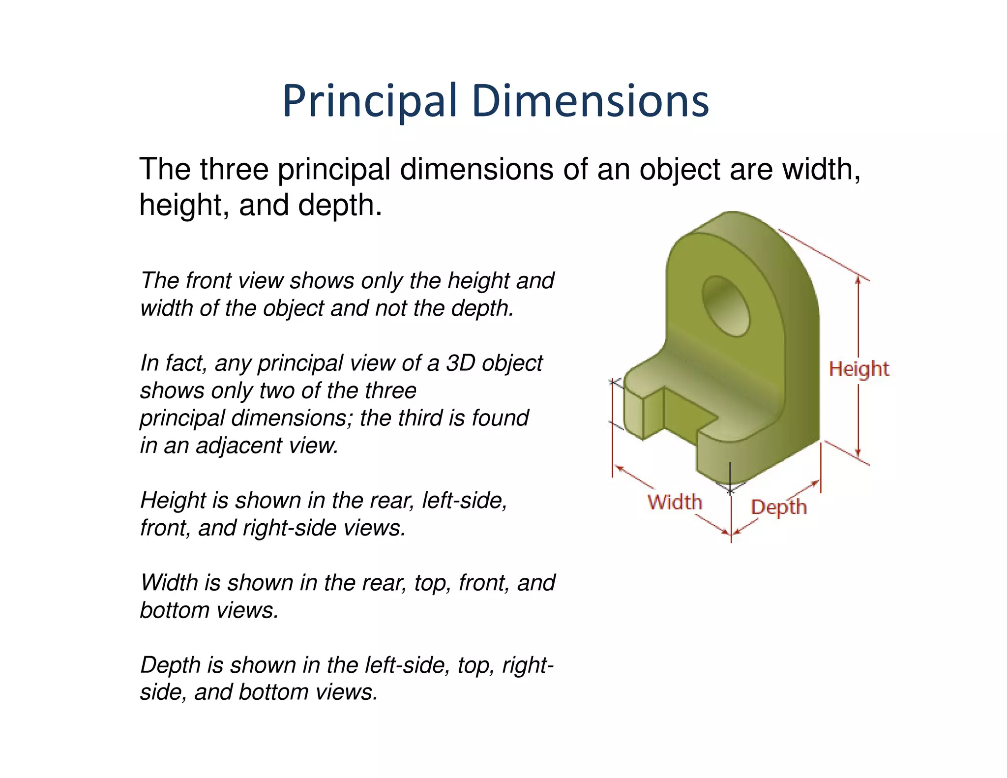


The document discusses multi-view orthographic projections used in technical drawing. It defines key terms like projection, view, and orthographic projections. It explains the different reference planes used - horizontal plane, vertical frontal plane, and profile plane. It also discusses the different views - front view, top view, and side view. It describes the first angle and third angle projection systems and methods. It explains how to project views of points, lines, planes and solids by using the different reference planes and projection lines.