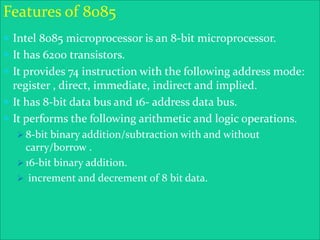
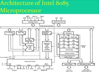
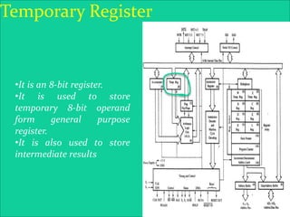
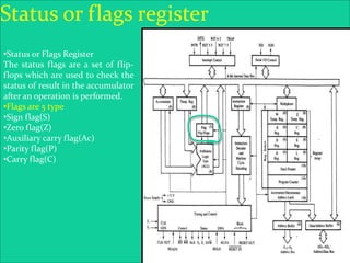
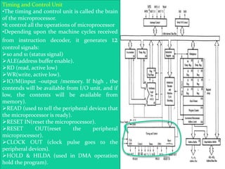
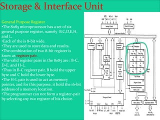
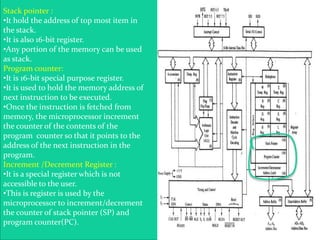
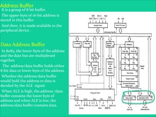
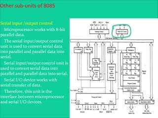
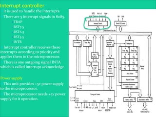
8085
Presentation
Prepared By: K.Brijendra Shankar (BCA 4th Sem)
What is a Microprocessor?
 The word comes from the combination micro and processor.
-Processor means a device that processes whatever. In this
context processor means a device that processes numbers,
specifically binary numbers, 0’s and 1’s.
 To process means to manipulate. It is a general term that
describes all manipulation. Again in this content, it means to
perform certain operations on the numbers that depend on
the microprocessor’s design.
Features of 8085
 Intel 8085 microprocessor is an 8-bit microprocessor.
 It has 6200 transistors.
 It provides 74 instruction with the following address mode:
register , direct, immediate, indirect and implied.
 It has 8-bit data bus and 16- address data bus.
 It performs the following arithmetic and logic operations.
 8-bit binary addition/subtraction with and without
carry/borrow .
 16-bit binary addition.
 increment and decrement of 8 bit data.
8085 Microprocessor Architecture
 8-bit general purpose μp
 Capable of addressing 64 k of memory
 Has 40 pins
 Requires +5 v power supply
 Can operate with 3 MHz clock
Architecture of Intel 8085
Microprocessor
Intel 8085 Microprocessor
 Microprocessor consists of
 Control unit: control microprocessor operations.
 ALU: performs data processing function.
 Registers: provide storage internal to CPU.
 Interrupts
 Internal data bus
Processing unit
Accumulator
•The accumulator is the main
storage of the microprocessor. It is
called register ‘A’
•The accumulator is an 8-bit
register that is a part of
arithmetic/logic unit (ALU). This
register is used to store 8-bit data
and to performed arithmetic and
logic operations.
•It always contains one of the
operands on the arithmetic/logic
operation has to be performed.
Arithmetic logic unit (ALU)
•The arithmetic logic unit (ALU) is
the heart of microprocessor.
•It performs various arithmetic
operations and logical operations on
the data available form the
accumulator and temporary or
general purpose registers and under
the influence of the timing and
control unit.
EX-
•Arithmetic operations : addition,
subtraction, increment, decrement,
etc.
•Logic operations : AND, OR,X-OR &
complement.
•Other operations : rotate, clear, shift,
etc.
Temporary Register
•It is an 8-bit register.
•It is used to store
temporary 8-bit operand
form general purpose
register.
•It is also used to store
intermediate results
Status or flags register
•Status or Flags Register
The status flags are a set of flip-
flops which are used to check the
status of result in the accumulator
after an operation is performed.
•Flags are 5 type
•Sign flag(S)
•Zero flag(Z)
•Auxiliary carry flag(Ac)
•Parity flag(P)
•Carry flag(C)
The Instruction unit
Instruction register :
•It is used to hold the current
instruction which the
microprocessor is about to execute.
•the instruction read from memory
is place in it.
•It is an 8-bit register.
Instruction decoder :
•It interprets the instruction stored
in instruction register.
•It generates various machine cycles
depending upon the instruction.
•The machine cycles are then given
to the timing and control unit.
Timing and Control Unit
•The timing and control unit is called the brain
of the microprocessor.
•It control all the operations of microprocessor
•Depending upon the machine cycles received
from instruction decoder, it generates 12
control signals:
s0 and s1 (status signal)
ALE(address buffer enable).
RD (read, active low)
WR(write, active low).
IO/M(input –output /memory. If high , the
contends will be available from I/O unit, and if
low, the contents will be available from
memory).
READ (used to tell the peripheral devices that
the microprocessor is ready).
RESET IN(reset the microprocessor).
RESET OUT(reset the peripheral
microprocessor).
CLOCK OUT (clock pulse goes to the
peripheral devices).
HOLD & HILDA (used in DMA operation
hold the program).
Storage & Interface Unit
General Purpose Register
•The 8085 microprocessor has a set of six
general purpose register, namely B,C,D,E,H,
and L.
•Each of the is 8-bit wide.
•They are used to store data and results.
•The combination of two 8-bit register is
know as register pair.
•The valid register pairs in the 8085 are : B-C,
D-E, and H-L.
•Thus in B-C register pair, B hold the upper
byte and C hold the lower byte.
•The H-L pair is used to act as memory
pointer, and for this purpose, it hold the 16-bit
address of a memory location.
•The programmer can not form a register-pair
by selecting any two register of his choice.
Stack pointer :
•It hold the address of top most item in
the stack.
•It is also 16-bit register.
•Any portion of the memory can be used
as stack.
Program counter:
•It is 16-bit special purpose register.
•It is used to hold the memory address of
next instruction to be executed.
•Once the instruction is fetched from
memory, the microprocessor increment
the counter of the contents of the
program counter so that it points to the
address of the next instruction in the
program.
Increment /Decrement Register :
•It is a special register which is not
accessible to the user.
•This is register is used by the
microprocessor to increment/decrement
the counter of stack pointer (SP) and
program counter(PC).
Address Buffer
•It is a group of 8 bit buffer.
•The upper-byte of 16-bit address is
stored in this buffer.
•And then, it is made available to the
peripheral device .
Data Address Buffer
•In 8085, the lower-byte of the address
and the data bus are multiplexed
together.
• The address/data buffer holds either
8-bit data or lower-byte of the address.
•Whether the address/data buffer
would hold the address or data is
decided by the ALE signal.
•When ALE is high, the address /data
buffer contains the lower byte of
address and when ALE is low, the
address/data buffer contains data.
Other sub-units of 8085
Serial input /output control
Microprocessor works with 8-bit
parallel data.
The serial input/output control
unit is used to convert serial data
into parallel and parallel data into
serial.
Serial input/output control unit is
used to convert serial data into
parallel and parallel data into serial.
Serial I/O device works with
serial transfer of data.
Therefore, this unit is the
interface between microprocessor
and serial I/O devices.
Interrupt controller
it is used to handle the interrupts.
There are 5 interrupt signals in 8085.
TRAP
RST7.5
RST6.5
RST5.5
INTR
Interrupt controller receives these
interrupts according to priority and
applies them to the microprocessor.
There is one outgoing signal INTA
which is called interrupt acknowledge.
Power supply
This unit provides +5v power supply
to the microprocessor.
The microprocessor needs +5v power
supply for it operation.
8085 architecture

8085 architecture

  • 1.
  • 2.
    What is aMicroprocessor?  The word comes from the combination micro and processor. -Processor means a device that processes whatever. In this context processor means a device that processes numbers, specifically binary numbers, 0’s and 1’s.  To process means to manipulate. It is a general term that describes all manipulation. Again in this content, it means to perform certain operations on the numbers that depend on the microprocessor’s design.
  • 3.
    Features of 8085 Intel 8085 microprocessor is an 8-bit microprocessor.  It has 6200 transistors.  It provides 74 instruction with the following address mode: register , direct, immediate, indirect and implied.  It has 8-bit data bus and 16- address data bus.  It performs the following arithmetic and logic operations.  8-bit binary addition/subtraction with and without carry/borrow .  16-bit binary addition.  increment and decrement of 8 bit data.
  • 4.
    8085 Microprocessor Architecture 8-bit general purpose μp  Capable of addressing 64 k of memory  Has 40 pins  Requires +5 v power supply  Can operate with 3 MHz clock
  • 5.
    Architecture of Intel8085 Microprocessor
  • 6.
    Intel 8085 Microprocessor Microprocessor consists of  Control unit: control microprocessor operations.  ALU: performs data processing function.  Registers: provide storage internal to CPU.  Interrupts  Internal data bus
  • 7.
    Processing unit Accumulator •The accumulatoris the main storage of the microprocessor. It is called register ‘A’ •The accumulator is an 8-bit register that is a part of arithmetic/logic unit (ALU). This register is used to store 8-bit data and to performed arithmetic and logic operations. •It always contains one of the operands on the arithmetic/logic operation has to be performed.
  • 8.
    Arithmetic logic unit(ALU) •The arithmetic logic unit (ALU) is the heart of microprocessor. •It performs various arithmetic operations and logical operations on the data available form the accumulator and temporary or general purpose registers and under the influence of the timing and control unit. EX- •Arithmetic operations : addition, subtraction, increment, decrement, etc. •Logic operations : AND, OR,X-OR & complement. •Other operations : rotate, clear, shift, etc.
  • 9.
    Temporary Register •It isan 8-bit register. •It is used to store temporary 8-bit operand form general purpose register. •It is also used to store intermediate results
  • 10.
    Status or flagsregister •Status or Flags Register The status flags are a set of flip- flops which are used to check the status of result in the accumulator after an operation is performed. •Flags are 5 type •Sign flag(S) •Zero flag(Z) •Auxiliary carry flag(Ac) •Parity flag(P) •Carry flag(C)
  • 11.
    The Instruction unit Instructionregister : •It is used to hold the current instruction which the microprocessor is about to execute. •the instruction read from memory is place in it. •It is an 8-bit register. Instruction decoder : •It interprets the instruction stored in instruction register. •It generates various machine cycles depending upon the instruction. •The machine cycles are then given to the timing and control unit.
  • 12.
    Timing and ControlUnit •The timing and control unit is called the brain of the microprocessor. •It control all the operations of microprocessor •Depending upon the machine cycles received from instruction decoder, it generates 12 control signals: s0 and s1 (status signal) ALE(address buffer enable). RD (read, active low) WR(write, active low). IO/M(input –output /memory. If high , the contends will be available from I/O unit, and if low, the contents will be available from memory). READ (used to tell the peripheral devices that the microprocessor is ready). RESET IN(reset the microprocessor). RESET OUT(reset the peripheral microprocessor). CLOCK OUT (clock pulse goes to the peripheral devices). HOLD & HILDA (used in DMA operation hold the program).
  • 13.
    Storage & InterfaceUnit General Purpose Register •The 8085 microprocessor has a set of six general purpose register, namely B,C,D,E,H, and L. •Each of the is 8-bit wide. •They are used to store data and results. •The combination of two 8-bit register is know as register pair. •The valid register pairs in the 8085 are : B-C, D-E, and H-L. •Thus in B-C register pair, B hold the upper byte and C hold the lower byte. •The H-L pair is used to act as memory pointer, and for this purpose, it hold the 16-bit address of a memory location. •The programmer can not form a register-pair by selecting any two register of his choice.
  • 14.
    Stack pointer : •Ithold the address of top most item in the stack. •It is also 16-bit register. •Any portion of the memory can be used as stack. Program counter: •It is 16-bit special purpose register. •It is used to hold the memory address of next instruction to be executed. •Once the instruction is fetched from memory, the microprocessor increment the counter of the contents of the program counter so that it points to the address of the next instruction in the program. Increment /Decrement Register : •It is a special register which is not accessible to the user. •This is register is used by the microprocessor to increment/decrement the counter of stack pointer (SP) and program counter(PC).
  • 15.
    Address Buffer •It isa group of 8 bit buffer. •The upper-byte of 16-bit address is stored in this buffer. •And then, it is made available to the peripheral device . Data Address Buffer •In 8085, the lower-byte of the address and the data bus are multiplexed together. • The address/data buffer holds either 8-bit data or lower-byte of the address. •Whether the address/data buffer would hold the address or data is decided by the ALE signal. •When ALE is high, the address /data buffer contains the lower byte of address and when ALE is low, the address/data buffer contains data.
  • 16.
    Other sub-units of8085 Serial input /output control Microprocessor works with 8-bit parallel data. The serial input/output control unit is used to convert serial data into parallel and parallel data into serial. Serial input/output control unit is used to convert serial data into parallel and parallel data into serial. Serial I/O device works with serial transfer of data. Therefore, this unit is the interface between microprocessor and serial I/O devices.
  • 17.
    Interrupt controller it isused to handle the interrupts. There are 5 interrupt signals in 8085. TRAP RST7.5 RST6.5 RST5.5 INTR Interrupt controller receives these interrupts according to priority and applies them to the microprocessor. There is one outgoing signal INTA which is called interrupt acknowledge. Power supply This unit provides +5v power supply to the microprocessor. The microprocessor needs +5v power supply for it operation.