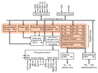
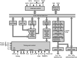
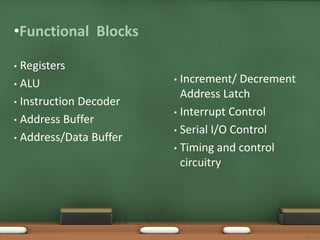
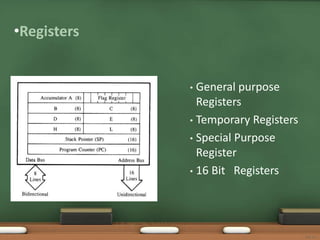
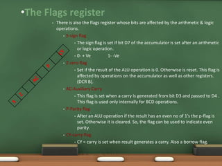
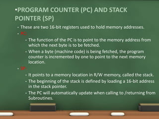
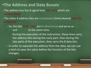
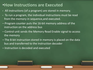
8085 Architecture
Varun Sukheja
Student 6th semester
Department of Computer Science & Engineering
Lakshmi Narain College of Technology and Science
•Functional Blocks
• Registers
• ALU
• Instruction Decoder
• Address Buffer
• Address/Data Buffer
• Increment/ Decrement
Address Latch
• Interrupt Control
• Serial I/O Control
• Timing and control
circuitry
SJCET
•Registers
• General purpose
Registers
• Temporary Registers
• Special Purpose
Register
• 16 Bit Registers
SJCET
•The Flags register
• There is also the flags register whose bits are affected by the arithmetic & logic
operations.
• S-sign flag
• The sign flag is set if bit D7 of the accumulator is set after an arithmetic
or logic operation.
• 0- + Ve 1- -Ve
• Z-zero flag
• Set if the result of the ALU operation is 0. Otherwise is reset. This flag is
affected by operations on the accumulator as well as other registers.
(DCR B).
• AC-Auxiliary Carry
• This flag is set when a carry is generated from bit D3 and passed to D4 .
This flag is used only internally for BCD operations.
• P-Parity flag
• After an ALU operation if the result has an even no of 1’s the p-flag is
set. Otherwise it is cleared. So, the flag can be used to indicate even
parity.
• CY-carry flag
• CY = carry is set when result generates a carry. Also a borrow flag.
SJCET
•PROGRAM COUNTER (PC) AND STACK
POINTER (SP)
• These are two 16-bit registers used to hold memory addresses.
• PC:
• The function of the PC is to point to the memory address from
which the next byte is to be fetched.
• When a byte (machine code) is being fetched, the program
counter is incremented by one to point to the next memory
location.
• SP:
• It points to a memory location in R/W memory, called the stack.
• The beginning of the stack is defined by loading a 16-bit address
in the stack pointer.
• The PC will automatically update when calling to /returning from
Subroutines.
•The ALU
• In addition to the arithmetic & logic circuits, the ALU includes
the accumulator, which is part of every arithmetic & logic
operation.
• Also, the ALU includes a temporary register used for holding
data temporarily during the execution of the operation. This
temporary register is not accessible by the programmer.
SJCET
•The Address and Data Busses
• The address bus has 8 signal lines A8 – A15 which are
unidirectional.
• The other 8 address bits are multiplexed (time shared) with the
8 data bits.
• So, the bits AD0 – AD7 are bi-directional and serve as A0 –
A7 and D0 – D7 at the same time.
• During the execution of the instruction, these lines carry
the address bits during the early part, then during the
late parts of the execution, they carry the 8 data bits.
• In order to separate the address from the data, we can use
a latch to save the value before the function of the bits
changes.
SJCET
•How Instructions are Executed
• All instructions (of a program) are stored in memory.
• To run a program, the individual instructions must be read
from the memory in sequence,and executed.
– Program counter puts the 16‐bit memory address of the
instruction on the address bus
– Control unit sends the Memory Read Enable signal to access
the memory
– The 8‐bit instruction stored in memory is placed on the data
bus and transferred to the instruction decoder
– Instruction is decoded and executed
SJCET

8085 architecture

  • 1.
    8085 Architecture Varun Sukheja Student6th semester Department of Computer Science & Engineering Lakshmi Narain College of Technology and Science
  • 4.
    •Functional Blocks • Registers •ALU • Instruction Decoder • Address Buffer • Address/Data Buffer • Increment/ Decrement Address Latch • Interrupt Control • Serial I/O Control • Timing and control circuitry SJCET
  • 5.
    •Registers • General purpose Registers •Temporary Registers • Special Purpose Register • 16 Bit Registers SJCET
  • 6.
    •The Flags register •There is also the flags register whose bits are affected by the arithmetic & logic operations. • S-sign flag • The sign flag is set if bit D7 of the accumulator is set after an arithmetic or logic operation. • 0- + Ve 1- -Ve • Z-zero flag • Set if the result of the ALU operation is 0. Otherwise is reset. This flag is affected by operations on the accumulator as well as other registers. (DCR B). • AC-Auxiliary Carry • This flag is set when a carry is generated from bit D3 and passed to D4 . This flag is used only internally for BCD operations. • P-Parity flag • After an ALU operation if the result has an even no of 1’s the p-flag is set. Otherwise it is cleared. So, the flag can be used to indicate even parity. • CY-carry flag • CY = carry is set when result generates a carry. Also a borrow flag. SJCET
  • 7.
    •PROGRAM COUNTER (PC)AND STACK POINTER (SP) • These are two 16-bit registers used to hold memory addresses. • PC: • The function of the PC is to point to the memory address from which the next byte is to be fetched. • When a byte (machine code) is being fetched, the program counter is incremented by one to point to the next memory location. • SP: • It points to a memory location in R/W memory, called the stack. • The beginning of the stack is defined by loading a 16-bit address in the stack pointer. • The PC will automatically update when calling to /returning from Subroutines.
  • 8.
    •The ALU • Inaddition to the arithmetic & logic circuits, the ALU includes the accumulator, which is part of every arithmetic & logic operation. • Also, the ALU includes a temporary register used for holding data temporarily during the execution of the operation. This temporary register is not accessible by the programmer. SJCET
  • 9.
    •The Address andData Busses • The address bus has 8 signal lines A8 – A15 which are unidirectional. • The other 8 address bits are multiplexed (time shared) with the 8 data bits. • So, the bits AD0 – AD7 are bi-directional and serve as A0 – A7 and D0 – D7 at the same time. • During the execution of the instruction, these lines carry the address bits during the early part, then during the late parts of the execution, they carry the 8 data bits. • In order to separate the address from the data, we can use a latch to save the value before the function of the bits changes. SJCET
  • 10.
    •How Instructions areExecuted • All instructions (of a program) are stored in memory. • To run a program, the individual instructions must be read from the memory in sequence,and executed. – Program counter puts the 16‐bit memory address of the instruction on the address bus – Control unit sends the Memory Read Enable signal to access the memory – The 8‐bit instruction stored in memory is placed on the data bus and transferred to the instruction decoder – Instruction is decoded and executed SJCET