Operational Amplifiers
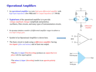
An operationalamplifier is a very high gain differential amplifier with
high input impedance (few MΩ) and low output impedance (< 100 Ω).
Differential
Amplifier
The basic circuit is made using a difference amplifier having
two inputs (plus and minus) and at least one output.
Typical uses of the operational amplifier is to provide:
voltage amplitude changes (amplitude and polarity),
oscillators, filter circuits, and many types of instrumentation circuits.
An op-amp contains a number of differential amplifier stages to achieve a
very high voltage gain.
Symbol of an Operational Amplifier is shown here.
The plus (+) input (Non-Inverting) produces an output that is in
phase with the signal applied.
The minus (-) input (Inverting) results in an opposite-polarity
output.
3.
Operational Amplifiers
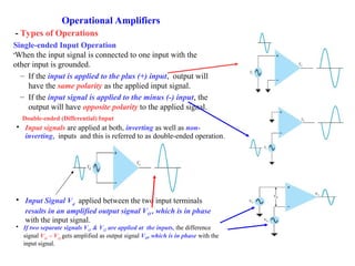
Single-ended InputOperation
When the input signal is connected to one input with the
other input is grounded.
– If the input is applied to the plus (+) input, output will
have the same polarity as the applied input signal.
– If the input signal is applied to the minus (-) input, the
output will have opposite polarity to the applied signal.
Double-ended (Differential) Input
Input signals are applied at both, inverting as well as non-
inverting, inputs and this is referred to as double-ended operation.
Input Signal Vd
applied between the two input terminals
results in an amplified output signal VO , which is in phase
with the input signal.
If two separate signals Vi1 & Vi2 are applied at the inputs, the difference
signal Vi1
– Vi2
gets amplified as output signal VO, which is in phase with the
input signal.
- Types of Operations
4.
Attributes of anIdeal Op Amp
An ideal op-amp circuit has infinite input impedance, zero output impedance, and infinite voltage gain. A
summary of ideal Op Amp attributes is given below:
IDEAL OP AMP ATTRIBUTES
Infinite Differential Gain
Zero Common Mode Gain
Zero Offset Voltage
Zero Bias Current
Infinite Bandwidth
OP AMP INPUT ATTRIBUTES
Infinite Impedance
Responds to Differential Voltages
Does not Respond to Common Mode Voltages
OP AMP OUTPUT ATTRIBITES
Zero Impedance
5.
Basic Op Amp
Thebasic op-amp acts as a constant-gain multiplier.
An input signal V1
is applied through resistor R1
to the (-) input. The output is fed back to
the same (-) input through resistor Rf
.
The (+) input is connected to ground.
Since the input signal is at the (-) input, the resulting output V0
is opposite in phase to the input signal.
The ac equivalent circuit of op amp has Ri
as input resistance and Ro
as output resistance.
6.
Basic Op Amp
Theac equivalent circuit of op amp has Ri
as input resistance and Ro
as output resistance.
In an ideal op-amp equivalent circuit – Ri
is replaced by an infinite resistance and Ro
by a zero resistance.
• The basic circuit connection using an op-amp is shown here.
• An input signal V1 is applied through resistor R1 to the minus input.
• The circuit provides operation as a constant-gain multiplier.
• Plus (+) input is connected to ground.
• Output is connected back to the same minus input through resistor Rf .
• Input Signal V1 is applied to the minus input, the resulting output is opposite in phase to the
input signal. Figure below shows the op-amp replaced by its ac equivalent circuit.
Redrawing the equivalent circuit:-
The Gain of this op amp network is given as AV = v
Negative sign indicates that output signal is 180
degrees out of phase with input signal.
7.
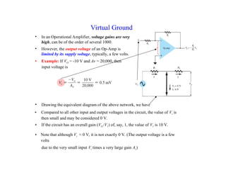
• In anOperational Amplifier, voltage gains are very
high, can be of the order of several 1000.
• Compared to all other input and output voltages in the circuit, the value of Vi is
then small and may be considered 0 V.
Virtual Ground
• However, the output voltage of an Op-Amp is
limited by its supply voltage, typically, a few volts.
• Example: If VO = -10 V and Av = 20,000, then
input voltage is
• If the circuit has an overall gain (VO /V1) of, say, 1, the value of V1 is 10 V.
• Note that although Vi ≈ 0 V, it is not exactly 0 V. (The output voltage is a few
volts
due to the very small input Vi times a very large gain Av)
• Drawing the equivalent diagram of the above network, we have
8.
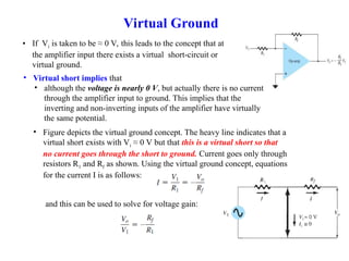
• Figure depictsthe virtual ground concept. The heavy line indicates that a
virtual short exists with Vi ≈ 0 V but that this is a virtual short so that
no current goes through the short to ground. Current goes only through
resistors R1 and Rf as shown. Using the virtual ground concept, equations
for the current I is as follows:
• If Vi is taken to be ≈ 0 V, this leads to the concept that at
the amplifier input there exists a virtual short-circuit or
virtual ground.
Virtual Ground
• Virtual short implies that
• although the voltage is nearly 0 V, but actually there is no current
through the amplifier input to ground. This implies that the
inverting and non-inverting inputs of the amplifier have virtually
the same potential.
and this can be used to solve for voltage gain:
9.
Basic Op Amp
UnityGain
Voltage gain =
• If Rf
= R1
then Voltage gain = -1
• Circuit provides a unity voltage gain with 180° phase inversion.
Constant-Magnitude Gain
If Rf
is some multiple of R1
, and the overall amplifier
gain is a constant. For example, if Rf
= 10R1
, then
Voltage gain = - Rf
/ R1
= -10
Circuit provides a voltage gain of 10 with a 180° phase
inversion from the input signal.
Selection of precise values of Rf
and R1
can provide wide
range of gains.
The gain is as accurate as the resistors used and is only
slightly affected by temperature and other circuit factors.
10.
Practical Op AmpCircuits
Inverting Amplifier
The most widely used constant-gain amplifier circuit is the
inverting amplifier.
The output is obtained by multiplying the input by a fixed or
constant gain, fixed by the input resistor ( R1
) and feedback
resistor ( Rf
).
This output is in inverted form with respect to the input.
Non-Inverting Amplifier:
Non-inverting amplifier or Constant-Gain multiplier circuit is
shown here.
To determine voltage gain, equivalent representation is
used.
Voltage across R1
is V1,
with Vi
=0 V,
Use voltage divider of R1
and Rf
,to get V1
This results in:-
11.
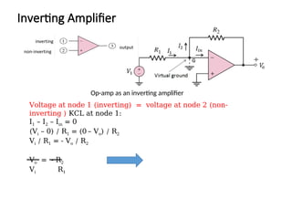
Op-amp as aninverting amplifier
Inverting Amplifier
Voltage at node 1 (inverting) = voltage at node 2 (non-
inverting ) KCL at node 1:
I1 – I2 – Iin = 0
(Vi – 0) / R1 = (0 – Vo) / R2
Vi / R1 = - Vo / R2
Vo = - R2
Vi R1
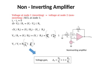
Noninverting amplifier
Non -Inverting Amplifier
Voltage at node 1 (inverting) = voltage at node 2 (non-
inverting ) KCL at node 1:
i1 – i2 = 0
(0– Vi) / R1 = (Vi – Vo) / R2
-(Vi / R1) = (Vi / R2) – (Vo / R2)
Vo / R2 = (Vi / R2) + (Vi / R1) = Vi 1 + 1
Vo / Vi = R2 1 + 1
R2 R1
R2 R1
15.
Practical Op AmpCircuits – Unity Follower
Unity Follower:
The unity-follower circuit, shown below provides a gain of unity (1) with no
polarity or phase reversal. From the equivalent circuit, it is clear that
Vo
= V1
The output is of same polarity and magnitude as the input. The circuit operates like an
emitter- or source-follower circuit except that the gain is exactly unity.
16.
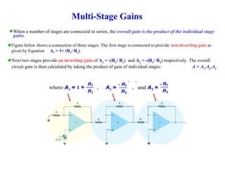
Multi-Stage Gains
When anumber of stages are connected in series, the overall gain is the product of the individual stage
gains.
Figure below shows a connection of three stages. The first stage is connected to provide non-inverting gain as
given by Equation A1 = 1+ (Rf
/ R1
).
Next two stages provide an inverting gain of A2
= -(Rf
/ R2
) and A3
= -(Rf
/ R3
) respectively. The overall
circuit gain is then calculated by taking the product of gain of individual stages: A = A1
.A2
.A3
Summing Amplifier
Summing Amplifier
Outputvoltage
i1 + i2 + i3 – i4 – 0 = 0
Similarly,
Example 8.2
Design a summing amplifier as shown in figure to produce a specific output signal, such that
vo = 1.25 – 2.5 cos t volt. Assume the input signals are vI1 = -1.0 V, vI2 = 0.5 cos t volt.
Assume the feedback resistance RF = 10 k
When the feedbackresistor of an inverter circuit is replaced by a capacitor the circuit is worked
as an integrator circuit -cause the output to respond to changes in the input voltage over time
Integrator
Integrator circuit
Differentiator
When the invertinginput terminal resistor of an op-amp inverter circuit is replaced by a capacitor
the circuit is worked as a differentiator circuit.
Differentiator circuit
Because Q = CVS
Calculating Gain andDesign Questions
INVERTING NON - INVERTING
Calculating Output and Design Questions
SUMMING AMPLIFIER
DIFFERENTIATOR
AMPLIFIER
INTEGRATOR AMPLIFIER
26.
Calculate the inputvoltage if the final output, VO is 10.08 V.
NON - INVERTING INVERTING INVERTING
Va Vb
Have to work backwards:
Vo = -(100/5) Vb
10.08 = -20 Vb
Vb = -0.504 V
Then:
Vb = -(5/5) Va
-0.504 = - Va
Va = 0.504 V
Finally:
Va = (1 + 10/5) V1
0.504 = 3V1
V1 = 0.168 V
27.
Calculate the outputvoltage, VO if V1 = V2 = 700 mV
INVERTING SUMMING
Va
Va = -(500/250) 0.7
Va = -1.4 V
Then:
Vo = - 500 [ Va / 100 + V2 / 50 ]
Vo = - 500 [ -1.4 / 100 + 0.7 / 50 ]
Vo = 0 V
28.
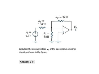
Calculate the outputvoltage VO of the operational amplifier
circuit as shown in the figure.
Answer: -3 V


![Calculate the output voltage, VO if V1 = V2 = 700 mV
INVERTING SUMMING
Va
Va = -(500/250) 0.7
Va = -1.4 V
Then:
Vo = - 500 [ Va / 100 + V2 / 50 ]
Vo = - 500 [ -1.4 / 100 + 0.7 / 50 ]
Vo = 0 V](https://image.slidesharecdn.com/lectureopamp-250810133316-ab415d3d/85/Lecture-on-Operational-Amplifiers-with-ppt-27-320.jpg)