Download to read offline
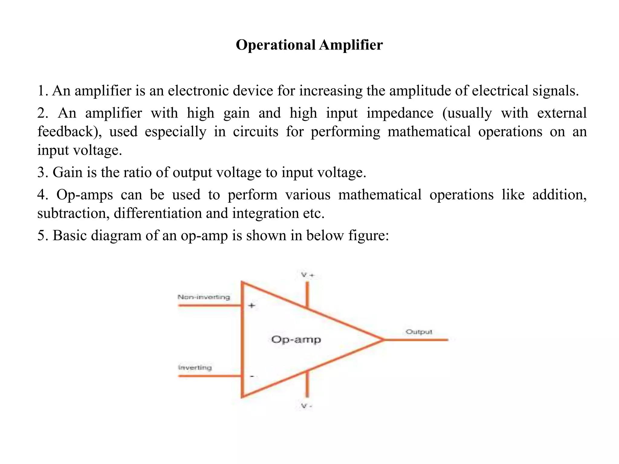
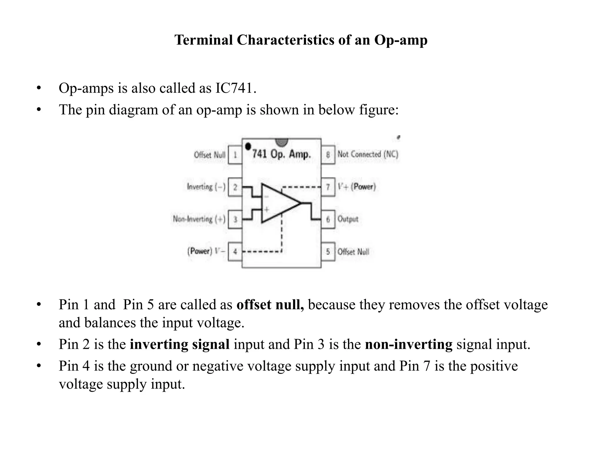


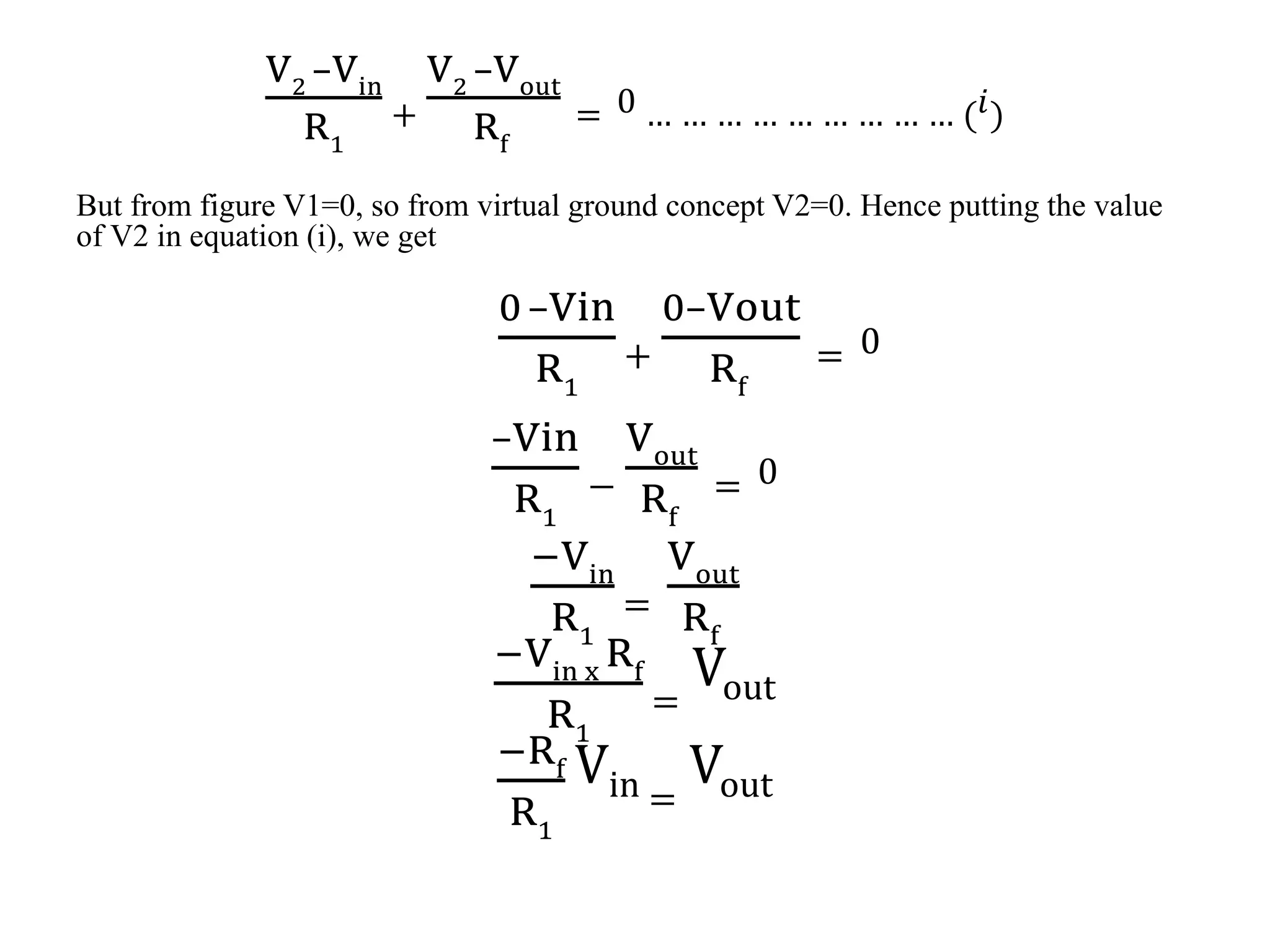

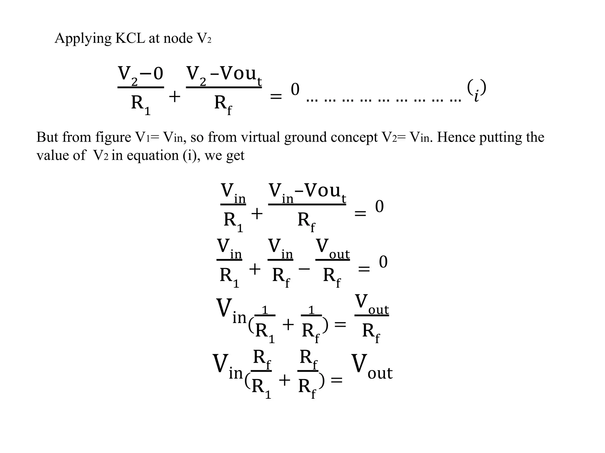

An operational amplifier (op-amp) is an electronic device that amplifies the difference between two input voltages. It has very high gain, very high input impedance, and very low output impedance. Op-amps can perform mathematical operations like addition, subtraction, integration, and differentiation. Key characteristics of an ideal op-amp include infinite input impedance, zero output impedance, infinite voltage gain, and zero offset voltage. Practical op-amps have finite characteristics. Op-amps can be configured as inverting or non-inverting amplifiers to produce output signals that are inverted or non-inverted versions of the input. Common op-amp applications include adders, subtractors, and active filters.


