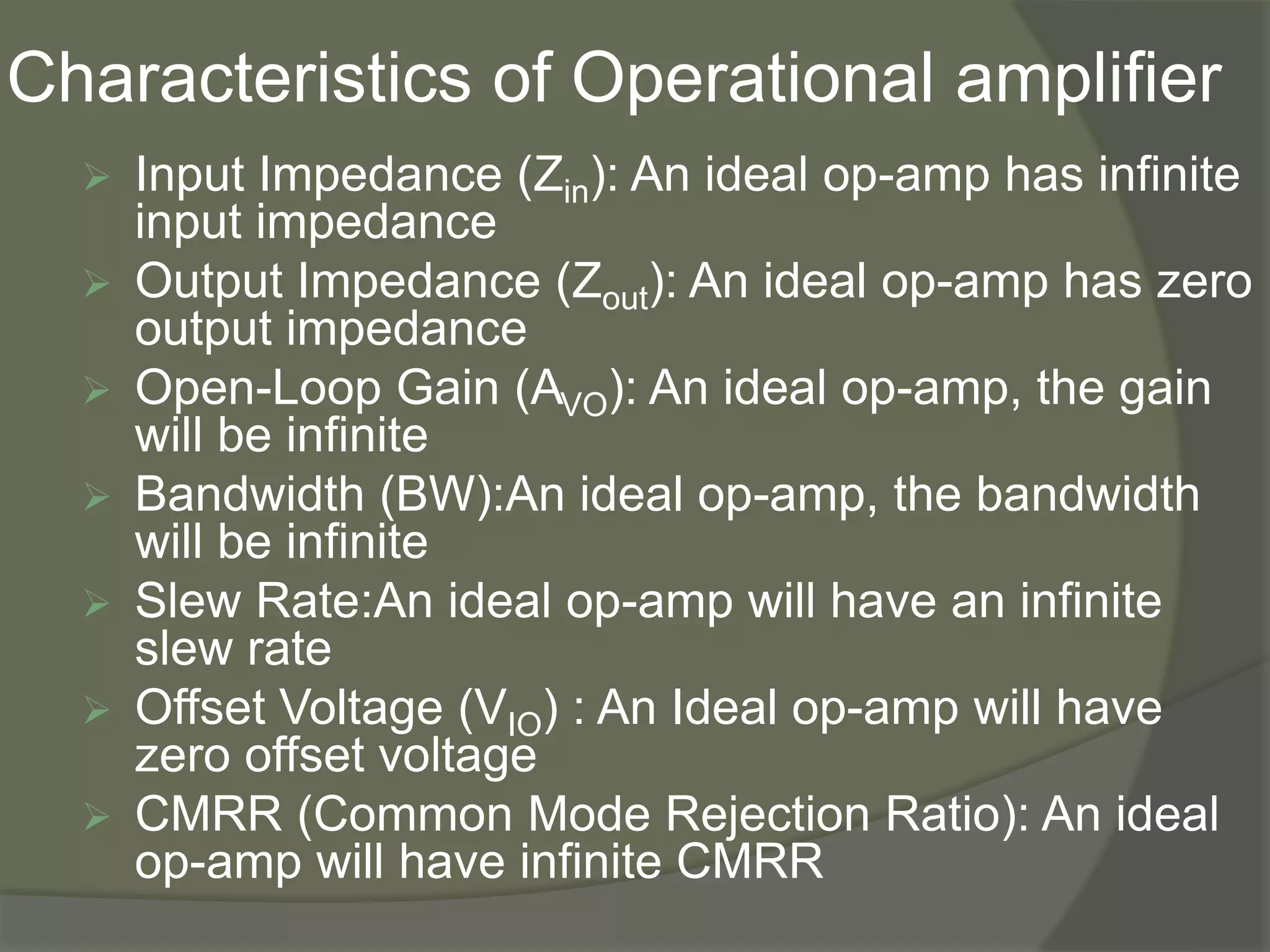
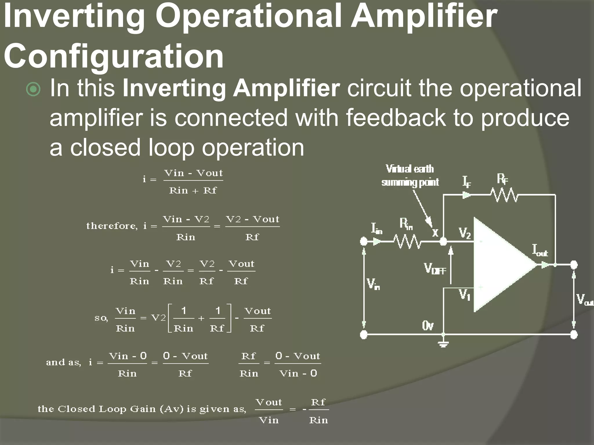
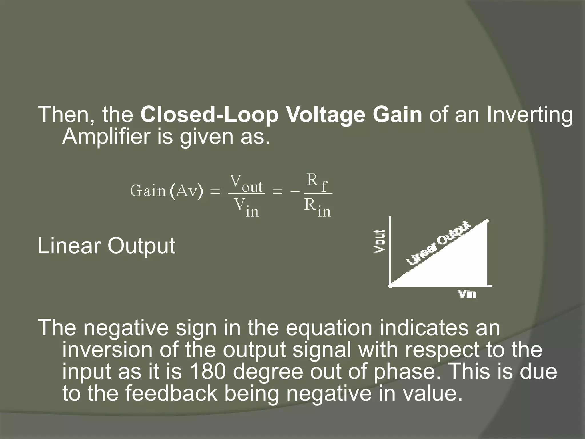
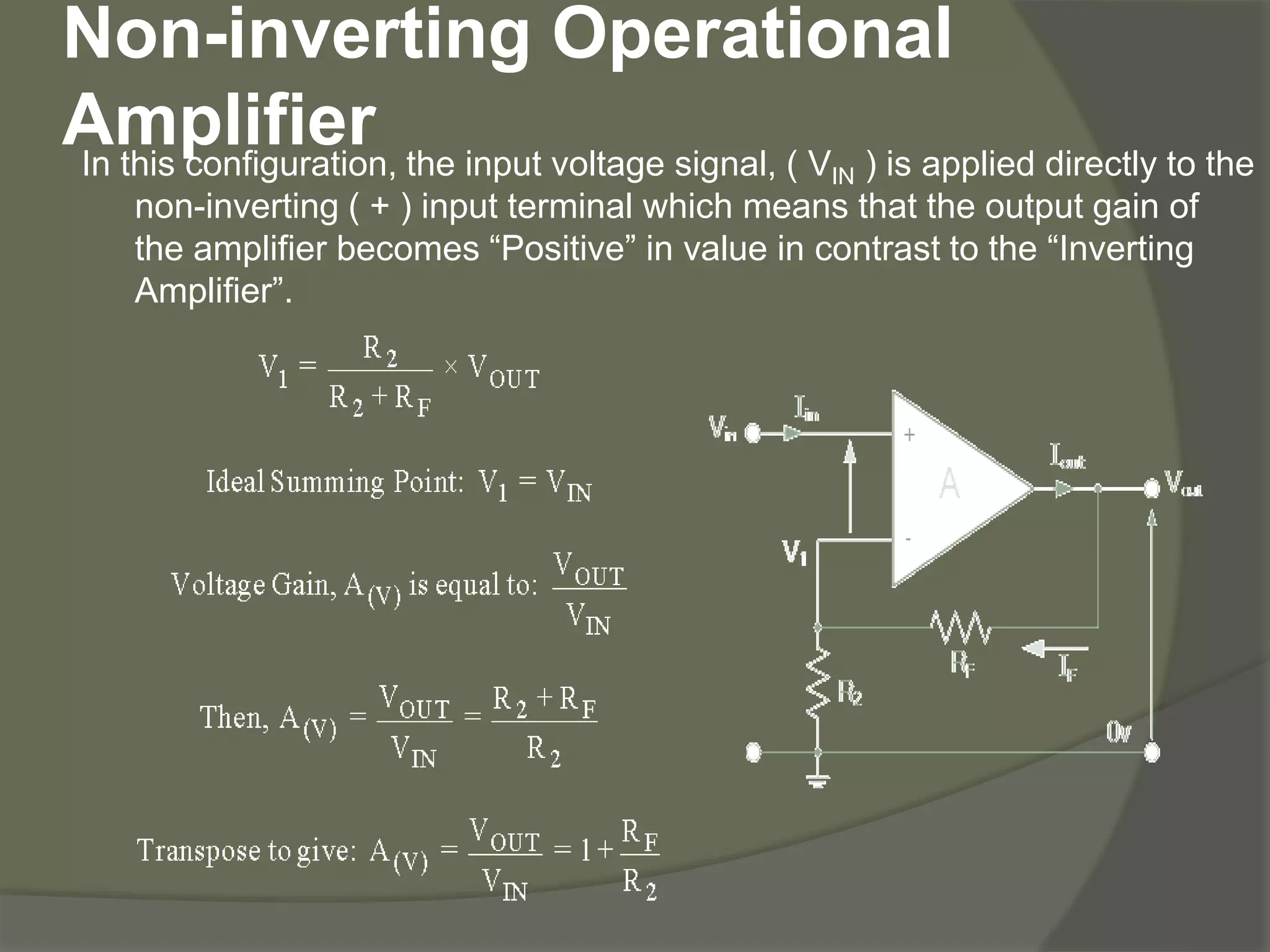
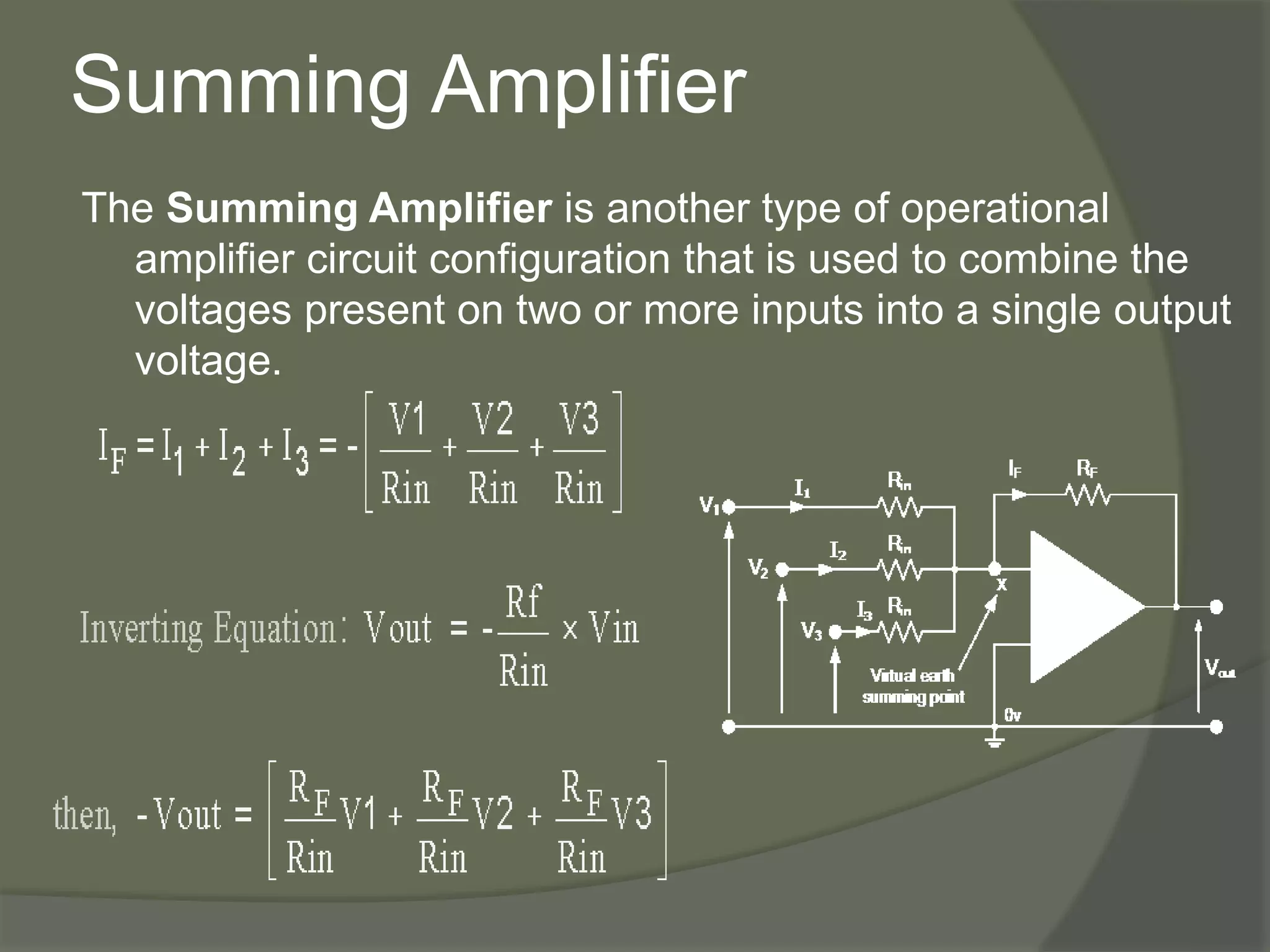
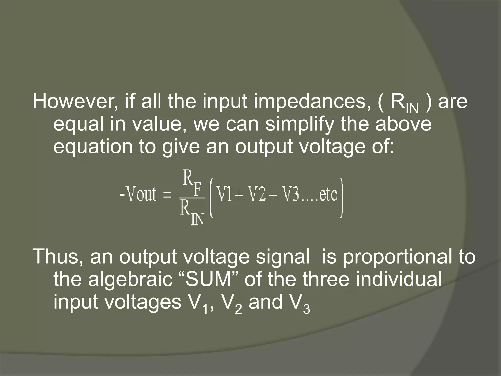
Part 01
Operational Amplifier
Dr. Krishna Jibon Mondal
Assistant Professor and Head
Department of Physics and Electronics
Shri Shankaracharya Mahavidyalaya, Bhilai
Introduction
An operational amplifier commonly known
as op-amp is a two-input single-output
differential voltage amplifier which is
characterized by
 high input impedance
 low output impedance
 high gain
Characteristics of Operational amplifier
 Input Impedance (Zin): An ideal op-amp has infinite
input impedance
 Output Impedance (Zout): An ideal op-amp has zero
output impedance
 Open-Loop Gain (AVO): An ideal op-amp, the gain
will be infinite
 Bandwidth (BW):An ideal op-amp, the bandwidth
will be infinite
 Slew Rate:An ideal op-amp will have an infinite
slew rate
 Offset Voltage (VIO) : An Ideal op-amp will have
zero offset voltage
 CMRR (Common Mode Rejection Ratio): An ideal
op-amp will have infinite CMRR
Inverting Operational Amplifier
Configuration
 In this Inverting Amplifier circuit the operational
amplifier is connected with feedback to produce
a closed loop operation
Then, the Closed-Loop Voltage Gain of an Inverting
Amplifier is given as.
Linear Output
The negative sign in the equation indicates an
inversion of the output signal with respect to the
input as it is 180 degree out of phase. This is due
to the feedback being negative in value.
Non-inverting Operational
AmplifierIn this configuration, the input voltage signal, ( VIN ) is applied directly to the
non-inverting ( + ) input terminal which means that the output gain of
the amplifier becomes “Positive” in value in contrast to the “Inverting
Amplifier”.
Then the closed loop voltage gain of a Non-
inverting Operational Amplifier will be given
as:
Summing Amplifier
The Summing Amplifier is another type of operational
amplifier circuit configuration that is used to combine the
voltages present on two or more inputs into a single output
voltage.
However, if all the input impedances, ( RIN ) are
equal in value, we can simplify the above
equation to give an output voltage of:
Thus, an output voltage signal is proportional to
the algebraic “SUM” of the three individual
input voltages V1, V2 and V3
THANK YOU

Operational amplifier part 01

  • 1.
    Part 01 Operational Amplifier Dr.Krishna Jibon Mondal Assistant Professor and Head Department of Physics and Electronics Shri Shankaracharya Mahavidyalaya, Bhilai
  • 2.
    Introduction An operational amplifiercommonly known as op-amp is a two-input single-output differential voltage amplifier which is characterized by  high input impedance  low output impedance  high gain
  • 3.
    Characteristics of Operationalamplifier  Input Impedance (Zin): An ideal op-amp has infinite input impedance  Output Impedance (Zout): An ideal op-amp has zero output impedance  Open-Loop Gain (AVO): An ideal op-amp, the gain will be infinite  Bandwidth (BW):An ideal op-amp, the bandwidth will be infinite  Slew Rate:An ideal op-amp will have an infinite slew rate  Offset Voltage (VIO) : An Ideal op-amp will have zero offset voltage  CMRR (Common Mode Rejection Ratio): An ideal op-amp will have infinite CMRR
  • 4.
    Inverting Operational Amplifier Configuration In this Inverting Amplifier circuit the operational amplifier is connected with feedback to produce a closed loop operation
  • 5.
    Then, the Closed-LoopVoltage Gain of an Inverting Amplifier is given as. Linear Output The negative sign in the equation indicates an inversion of the output signal with respect to the input as it is 180 degree out of phase. This is due to the feedback being negative in value.
  • 6.
    Non-inverting Operational AmplifierIn thisconfiguration, the input voltage signal, ( VIN ) is applied directly to the non-inverting ( + ) input terminal which means that the output gain of the amplifier becomes “Positive” in value in contrast to the “Inverting Amplifier”.
  • 7.
    Then the closedloop voltage gain of a Non- inverting Operational Amplifier will be given as:
  • 8.
    Summing Amplifier The SummingAmplifier is another type of operational amplifier circuit configuration that is used to combine the voltages present on two or more inputs into a single output voltage.
  • 9.
    However, if allthe input impedances, ( RIN ) are equal in value, we can simplify the above equation to give an output voltage of: Thus, an output voltage signal is proportional to the algebraic “SUM” of the three individual input voltages V1, V2 and V3
  • 10.