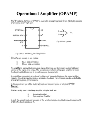
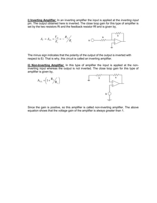
Operational Amplifier (OPAMP)
The OPerational AMPlifier or OPAMP is a versatile analog Integrated Circuit (IC) that is capable
of producing a very high gain.
OPAMPs can operate in two modes:
i) Open loop connection
ii) Closed loop connection
An amplifier is a circuit that receives a signal at its input and delivers an undistorted larger
version of the signal at its output. The operational amplifier is a high gain amplifier to which
feedback is added to control its overall response characteristic.
In closed loop connection, an external resistance is connected between the output and the
negative (inverting) input terminal as a negative feedback. Here, the gain can be controlled by
changing the values of the resistors.
In this experiment we will be studying the closed loop connection of a typical OPAMP.
THEORY
The two widely used closed loop amplifier using OPAMP are:
i) Inverting Amplifier
ii) Non-Inverting Amplifier
In both the cases the closed loop gain of the amplifier is determined by the input resistance Ri
and the feedback resistance Rf.
Fig: 741 IC (OPAMP) pin configuration
E+
E-
Vo
Fig: Circuit symbol
i) Inverting Amplifier: In an inverting amplifier the input is applied at the inverting input
pin. The output obtained here is inverted. The close loop gain for this type of amplifier is
set by the two resistors Ri and the feedback resistor Rf and is given by,
i
f
i
O
CLV R
R
E
V
AA 
The minus sign indicates that the polarity of the output of the output is inverted with
respect to Ei. That is why, this circuit is called an inverting amplifier.
ii) Non-Inverting Amplifier: In this type of amplifier the input is applied at the non-
inverting input whereas the output is not inverted. The close loop gain for this type of
amplifier is given by,





 
i
f
CL R
R
1A
Since the gain is positive, so this amplifier is called non-inverting amplifier. The above
equation shows that the voltage gain of the amplifier is always greater than 1.

Operational amplifier (OPAMP)

  • 1.
    Operational Amplifier (OPAMP) TheOPerational AMPlifier or OPAMP is a versatile analog Integrated Circuit (IC) that is capable of producing a very high gain. OPAMPs can operate in two modes: i) Open loop connection ii) Closed loop connection An amplifier is a circuit that receives a signal at its input and delivers an undistorted larger version of the signal at its output. The operational amplifier is a high gain amplifier to which feedback is added to control its overall response characteristic. In closed loop connection, an external resistance is connected between the output and the negative (inverting) input terminal as a negative feedback. Here, the gain can be controlled by changing the values of the resistors. In this experiment we will be studying the closed loop connection of a typical OPAMP. THEORY The two widely used closed loop amplifier using OPAMP are: i) Inverting Amplifier ii) Non-Inverting Amplifier In both the cases the closed loop gain of the amplifier is determined by the input resistance Ri and the feedback resistance Rf. Fig: 741 IC (OPAMP) pin configuration E+ E- Vo Fig: Circuit symbol
  • 2.
    i) Inverting Amplifier:In an inverting amplifier the input is applied at the inverting input pin. The output obtained here is inverted. The close loop gain for this type of amplifier is set by the two resistors Ri and the feedback resistor Rf and is given by, i f i O CLV R R E V AA  The minus sign indicates that the polarity of the output of the output is inverted with respect to Ei. That is why, this circuit is called an inverting amplifier. ii) Non-Inverting Amplifier: In this type of amplifier the input is applied at the non- inverting input whereas the output is not inverted. The close loop gain for this type of amplifier is given by,        i f CL R R 1A Since the gain is positive, so this amplifier is called non-inverting amplifier. The above equation shows that the voltage gain of the amplifier is always greater than 1.