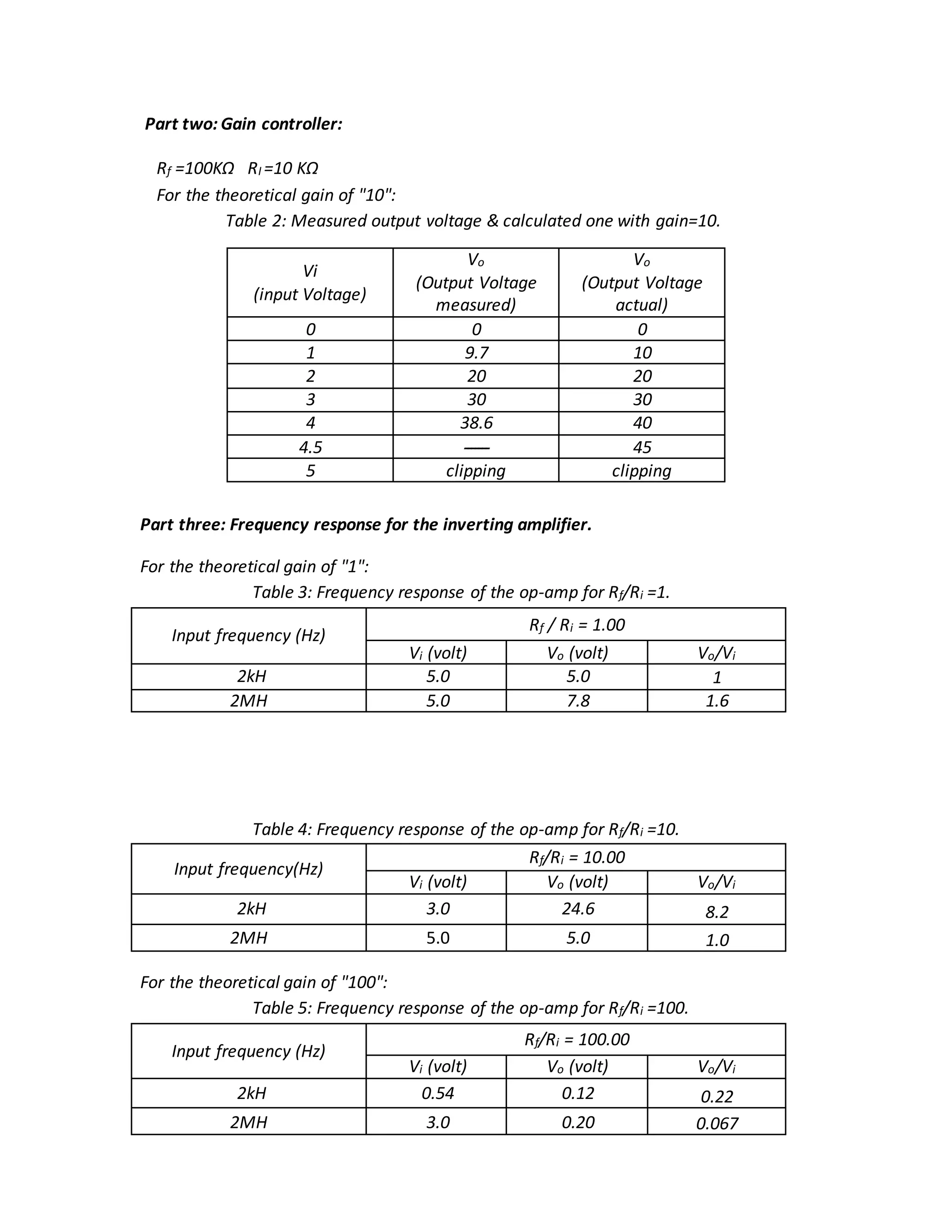
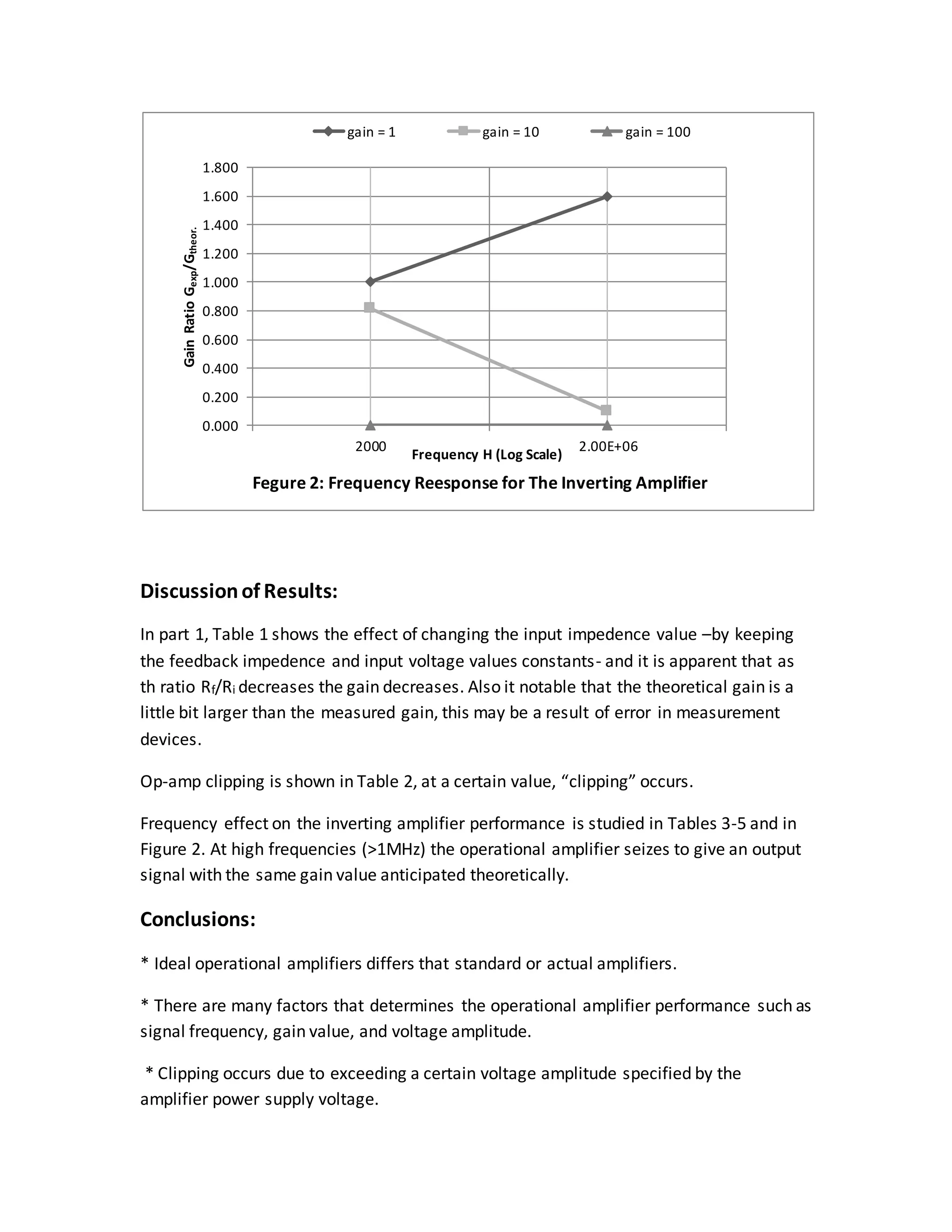
SlideShare a Scribd company logo
Jordan University of Science and Technology
Faculty of Engineering
Department of Mechanical Engineering
Instrumentation and Dynamic Systems Lab
Experiment #3: Op-amp
Abstract:
This experiment shows one type of op-amps called the inverting amplifier, which
amplify an input voltage signal and inverts its polarity. Many factors affecting the
inverting amplifier performance were studied briefly, namely; signal frequency,
theoretical gain value, and input signal amplitude. Each amplifier has a bandwidth value
that determines the value of frequency that doesn’t shelter more than 0.707 of the
input signal amplitude. At high gain values (G=100 ) the performance is very poor.
Clipping occurs when the input voltage exceed a limit value determined by the op-amp
power supply voltage.
Introduction:
Operational amplifiers are linear devices that have all the properties required for nearly
ideal DC amplification and are therefore used extensively in signal conditioning, filtering
or to perform mathematical operations such as add, subtract, integration and
differentiation.
An Operational Amplifier, or op-amp for short, is fundamentally a voltage amplifying
device designed to be used with external feedback components such as resistors and
capacitors between its output and input terminals. These feedback components
determine the resulting function or “operation” of the amplifier and by virtue of the
different feedback configurations whether resistive, capacitive or both, the amplifier can
perform a variety of different operations, giving rise to its name of “Operational
Amplifier”.
An Operational Amplifier is basically a three-terminal device which consists of two high
impedance inputs, one called the inverting Input, marked with a negative or “minus”
sign, ( – ) and the other one called the non-inverting Input, marked with a positive or
“plus” sign ( + ).
The third terminal represents the operational amplifiers output port which can both sink
and source either a voltage or a current. In a linear operational amplifier, the output
signal is the amplification factor, known as the amplifiers gain (G) multiplied by the
value of the input signal.
Voltage Gain:
The Voltage Gain (AV) of the operational amplifier can be found using the following
formula:
Voltage gain (G) =
𝑉𝑜
𝑉𝑖
and in Decibels or (dB) is given as:
Voltage Gain in dB = 20 log (G) = 20 log (
𝑉𝑜
𝑉𝑖
)
An Operational Amplifiers Bandwidth
The operational amplifiers bandwidth is the frequency range over which the voltage gain
of the amplifier is above 70.7% or -3dB (where 0dB is the maximum) of its maximum
output value as shown below.
Figure 2:Op-amp Bandwid
Equipments and instruments:
1- AC Function Generator: This device gives a square, sinusoidal, and ramp ac
signals at wide frequency range, is used to generate a sinusoidal input signal for
the operational amplifier.
2- Oscilloscope: A signal recording instrument that shows input signals on a screen,
it has many options that can be used to best suit the input signal to the screen. It
has two input terminals and can be used for comparison purposes. It was used to
measure the gain value of the op-amp.
3- Operational amplifier: AnOperationalAmplifierisbasicallyathree-terminal device
whichconsistsof twohighimpedance inputs,one calledthe invertingInput,marked
witha negative or“minus”sign,( – ) and the otherone calledthe non-invertingInput,
markedwitha positive or“plus”sign( + ).
4- Resistances.
Procedure:
Inverting amplifier as gain controller:
1. Connect the circuit as shown in figure 1.
2. Fix the input voltage to 2Ω p-p, and put feedback resistance Rf= 10kΩ.
3. For resistance Ri, use a variable resistance, and change it with a step of 2Ω,
starting from 2Ω to 20Ω. At each step measure Vo .
Frequency response for the inverting amplifier
1. Set the amplifier gain to unity, i.e. the input resistance equals the output one, for
instnace 100kΩ.
2. Fix an input rms voltage of 2V.
3. Change the frequency input from 10Hz – 0,1MHz, and measure the output
voltage for each change.
4. Tabulate the results and polt the measured gain agganist the input signal
frequency on a log scale.
5. Repeate the above steps with amplifier gain of 10 and 100.
Tabulate the results, and compare the measured gain with the theoretical one.
Figure 1: Non-Inverting Operational Amplifier
Theoretical Analysis:
-Vi - Vop-amp + (I1-I2) Rf + Vo = 0 …………………………... (1)
RiI1 + Rf (I1-I2) + Vo = 0 …………………………………… (2)
From eq. (2) we find
I1 = (RfI2-Vo) / (Rf+Ri)
Substitute in eq. (1)
-Vi - Vop-amp + ((RfI2-Vo)/ (Rf+Ri) – I2)Rf + Vo= 0
This is the general equation for the non-inverting op-amp.
But Vop-amp depends on I2, so if we assume that I2 = 0 for ideal amplifier, we find
that Vop-amp = 0 also,
then we conclude:
-Vi - (Vo/ (Rf+Ri)) Rf + Vo= 0
Vo (1 - (Rf/ (Rf+Ri)) = Vi
Vo/Vi = (Rf+Ri)/Ri
Vo/Vi = Theoretical gain = 1 + (Rf/Ri) for ideal op-amp
Results:
Part one: Inverting amplifier as gain controller
Rf =10kΩ (fixed)
Table 1: Theoretical and measured gain of the inverting op-amp.
Input
resistance Ri
(kΩ)
Input voltage
Vi (V)
Output voltage
Vo (V)
Measured gain
(Vo / Vi)
Theoretical
gain
(-Rf / Ri)
2 7.0 34.8 5.0 5.0
4 7.0 17.8 2.5 2.5
6 7.0 12 1.7 1.7
8 7.0 9.2 1.3 1.3
10 7.0 7 1 1.0
12 7.0 6.2 0.89 0.83
14 7.0 5.4 0.77 0.71
16 7.0 4.8 0.69 0.63
18 7.0 4.2 0.60 0.56
20 7.0 4 0.57 0.50
Sample of Calculation (at Ri = 8) : G = 9.3/7 =1.3
Part two: Gain controller:
Rf =100KΩ RI =10 KΩ
For the theoretical gain of "10":
Table 2: Measured output voltage & calculated one with gain=10.
Part three: Frequency response for the inverting amplifier.
For the theoretical gain of "1":
Table 3: Frequency response of the op-amp for Rf/Ri =1.
Input frequency (Hz)
Rf / Ri = 1.00
Vi (volt) Vo (volt) Vo/Vi
2kH 5.0 5.0 1
2MH 5.0 7.8 1.6
Table 4: Frequency response of the op-amp for Rf/Ri =10.
Input frequency(Hz)
Rf/Ri = 10.00
Vi (volt) Vo (volt) Vo/Vi
2kH 3.0 24.6 8.2
2MH 5.0 5.0 1.0
For the theoretical gain of "100":
Table 5: Frequency response of the op-amp for Rf/Ri =100.
Input frequency (Hz)
Rf/Ri = 100.00
Vi (volt) Vo (volt) Vo/Vi
2kH 0.54 0.12 0.22
2MH 3.0 0.20 0.067
Vi
(input Voltage)
Vo
(Output Voltage
measured)
Vo
(Output Voltage
actual)
0 0 0
1 9.7 10
2 20 20
3 30 30
4 38.6 40
4.5 ‫ـــــــ‬ 45
5 clipping clipping
Discussionof Results:
In part 1, Table 1 shows the effect of changing the input impedence value –by keeping
the feedback impedence and input voltage values constants- and it is apparent that as
th ratio Rf/Ri decreases the gain decreases. Also it notable that the theoretical gain is a
little bit larger than the measured gain, this may be a result of error in measurement
devices.
Op-amp clipping is shown in Table 2, at a certain value, “clipping” occurs.
Frequency effect on the inverting amplifier performance is studied in Tables 3-5 and in
Figure 2. At high frequencies (>1MHz) the operational amplifier seizes to give an output
signal with the same gain value anticipated theoretically.
Conclusions:
* Ideal operational amplifiers differs that standard or actual amplifiers.
* There are many factors that determines the operational amplifier performance such as
signal frequency, gain value, and voltage amplitude.
* Clipping occurs due to exceeding a certain voltage amplitude specified by the
amplifier power supply voltage.
0.000
0.200
0.400
0.600
0.800
1.000
1.200
1.400
1.600
1.800
2000 2.00E+06
GainRatioGexp/Gtheor.
Frequency H (Log Scale)
Fegure 2: Frequency Reesponse for The Inverting Amplifier
gain = 1 gain = 10 gain = 100
References:
http://www.electronics-tutorials.ws/opamp/opamp_1.html
Instrumentation and Dynamic Systems Lab Manual

More Related Content

What's hot

Two port network
Two port networkTwo port network
Two port network
Rajput Manthan
 
Voltage Amplifier
Voltage AmplifierVoltage Amplifier
Voltage Amplifier
Mayank Pandey
 
Chebyshev filter
Chebyshev filterChebyshev filter
Chebyshev filter
MOHAMMAD AKRAM
 
Voltage Regulators ppt
Voltage Regulators pptVoltage Regulators ppt
Voltage Regulators ppt
Gurkirat Singh
 
Operational Amplifier Part 1
Operational Amplifier Part 1Operational Amplifier Part 1
Operational Amplifier Part 1
Mukesh Tekwani
 
Field Effect Transistor
Field Effect TransistorField Effect Transistor
Field Effect Transistor
Jess Rangcasajo
 
Polar Plot
Polar PlotPolar Plot
Polar Plot
Hussain K
 
Transducer and instrumentation lab manual
Transducer and instrumentation lab manual Transducer and instrumentation lab manual
Transducer and instrumentation lab manual
awais ahmad
 
Chapter 7: Operational Amplifier (Op-Amp)
Chapter 7: Operational Amplifier (Op-Amp)Chapter 7: Operational Amplifier (Op-Amp)
Chapter 7: Operational Amplifier (Op-Amp)
JeremyLauKarHei
 
report of power electronics
report of power electronicsreport of power electronics
report of power electronics
Mohamad Nur Afham Shamsudin
 
Instrumentational Amplifier
Instrumentational Amplifier Instrumentational Amplifier
Instrumentational Amplifier
ZunAib Ali
 
Multivibrators
MultivibratorsMultivibrators
Multivibrators
PrabhudasuSir
 
Op amps
Op ampsOp amps
Power Electronics - DIAC & TRIAC
Power Electronics - DIAC & TRIACPower Electronics - DIAC & TRIAC
Power Electronics - DIAC & TRIAC
Burdwan University
 
555 Timer (detailed presentation)
555 Timer (detailed presentation)555 Timer (detailed presentation)
555 Timer (detailed presentation)
Tanish Gupta
 
INTRODUCTION TO LVDT,RVDT and Potentiometer
INTRODUCTION TO LVDT,RVDT and Potentiometer INTRODUCTION TO LVDT,RVDT and Potentiometer
INTRODUCTION TO LVDT,RVDT and Potentiometer
SACHINNikam39
 
KCL and KVL
KCL and KVLKCL and KVL
KCL and KVL
140120109032
 
Alternator / Synchronous Generator
Alternator / Synchronous GeneratorAlternator / Synchronous Generator
Alternator / Synchronous Generator
Ridwanul Hoque
 
Differential amplifier
Differential amplifierDifferential amplifier
Differential amplifier
Arpit Raval
 

What's hot (20)

Two port network
Two port networkTwo port network
Two port network
 
Voltage Amplifier
Voltage AmplifierVoltage Amplifier
Voltage Amplifier
 
Chebyshev filter
Chebyshev filterChebyshev filter
Chebyshev filter
 
Voltage Regulators ppt
Voltage Regulators pptVoltage Regulators ppt
Voltage Regulators ppt
 
Operational Amplifier Part 1
Operational Amplifier Part 1Operational Amplifier Part 1
Operational Amplifier Part 1
 
Oscillators
OscillatorsOscillators
Oscillators
 
Field Effect Transistor
Field Effect TransistorField Effect Transistor
Field Effect Transistor
 
Polar Plot
Polar PlotPolar Plot
Polar Plot
 
Transducer and instrumentation lab manual
Transducer and instrumentation lab manual Transducer and instrumentation lab manual
Transducer and instrumentation lab manual
 
Chapter 7: Operational Amplifier (Op-Amp)
Chapter 7: Operational Amplifier (Op-Amp)Chapter 7: Operational Amplifier (Op-Amp)
Chapter 7: Operational Amplifier (Op-Amp)
 
report of power electronics
report of power electronicsreport of power electronics
report of power electronics
 
Instrumentational Amplifier
Instrumentational Amplifier Instrumentational Amplifier
Instrumentational Amplifier
 
Multivibrators
MultivibratorsMultivibrators
Multivibrators
 
Op amps
Op ampsOp amps
Op amps
 
Power Electronics - DIAC & TRIAC
Power Electronics - DIAC & TRIACPower Electronics - DIAC & TRIAC
Power Electronics - DIAC & TRIAC
 
555 Timer (detailed presentation)
555 Timer (detailed presentation)555 Timer (detailed presentation)
555 Timer (detailed presentation)
 
INTRODUCTION TO LVDT,RVDT and Potentiometer
INTRODUCTION TO LVDT,RVDT and Potentiometer INTRODUCTION TO LVDT,RVDT and Potentiometer
INTRODUCTION TO LVDT,RVDT and Potentiometer
 
KCL and KVL
KCL and KVLKCL and KVL
KCL and KVL
 
Alternator / Synchronous Generator
Alternator / Synchronous GeneratorAlternator / Synchronous Generator
Alternator / Synchronous Generator
 
Differential amplifier
Differential amplifierDifferential amplifier
Differential amplifier
 

Viewers also liked

Instrumentation Lab. Experiment #4 Report: Op-Amps: Integrator, Differentiato...
Instrumentation Lab. Experiment #4 Report: Op-Amps: Integrator, Differentiato...Instrumentation Lab. Experiment #4 Report: Op-Amps: Integrator, Differentiato...
Instrumentation Lab. Experiment #4 Report: Op-Amps: Integrator, Differentiato...
mohammad zeyad
 
Instrumentation Lab. Experiment #2 Report: System Response Characteristics
Instrumentation Lab. Experiment #2 Report: System Response CharacteristicsInstrumentation Lab. Experiment #2 Report: System Response Characteristics
Instrumentation Lab. Experiment #2 Report: System Response Characteristics
mohammad zeyad
 
Instrumentation Lab. Experiment #6 Report: Strain Measurements 1
Instrumentation Lab. Experiment #6 Report: Strain Measurements 1Instrumentation Lab. Experiment #6 Report: Strain Measurements 1
Instrumentation Lab. Experiment #6 Report: Strain Measurements 1
mohammad zeyad
 
Instrumentation Lab. Experiment #12 Report: Lateral Beam Vibration
Instrumentation Lab. Experiment #12 Report: Lateral Beam VibrationInstrumentation Lab. Experiment #12 Report: Lateral Beam Vibration
Instrumentation Lab. Experiment #12 Report: Lateral Beam Vibration
mohammad zeyad
 
Instrumentation Lab. Experiment #8 Report: Thermocouples
Instrumentation Lab. Experiment #8 Report: ThermocouplesInstrumentation Lab. Experiment #8 Report: Thermocouples
Instrumentation Lab. Experiment #8 Report: Thermocouples
mohammad zeyad
 
Instrumentation Lab. Experiment #7 Report: Strain Measurements 2
Instrumentation Lab. Experiment #7 Report: Strain Measurements 2Instrumentation Lab. Experiment #7 Report: Strain Measurements 2
Instrumentation Lab. Experiment #7 Report: Strain Measurements 2
mohammad zeyad
 
Instrumentation Lab. Experiment#1 calibration (report)
Instrumentation Lab. Experiment#1 calibration (report)Instrumentation Lab. Experiment#1 calibration (report)
Instrumentation Lab. Experiment#1 calibration (report)
mohammad zeyad
 
IPM Global Project Management Software
IPM Global Project Management SoftwareIPM Global Project Management Software
IPM Global Project Management Software
Chana Stevenson
 
Av335 instrumentation lab report
Av335 instrumentation lab reportAv335 instrumentation lab report
Av335 instrumentation lab reportGaurav Vaibhav
 
JISC Legal OER Showcase
JISC Legal OER ShowcaseJISC Legal OER Showcase
JISC Legal OER Showcase
JISC Legal
 
Apollo Guidance Compter
Apollo Guidance CompterApollo Guidance Compter
Apollo Guidance Compter
Don Blanchet
 
Single stage bjt amplifier. experiment 6
Single stage bjt amplifier. experiment 6Single stage bjt amplifier. experiment 6
Single stage bjt amplifier. experiment 6
Karimi LordRamza
 
Final instrumentation lab manual
Final instrumentation lab manualFinal instrumentation lab manual
Final instrumentation lab manual
kishorereddy_btech
 
process control instrumentation lab and labview report
process control  instrumentation lab and labview  reportprocess control  instrumentation lab and labview  report
process control instrumentation lab and labview report
Hari Krishna
 
Nodal analysis
Nodal analysisNodal analysis
Nodal analysis
Dessy S. Ayu
 

Viewers also liked (15)

Instrumentation Lab. Experiment #4 Report: Op-Amps: Integrator, Differentiato...
Instrumentation Lab. Experiment #4 Report: Op-Amps: Integrator, Differentiato...Instrumentation Lab. Experiment #4 Report: Op-Amps: Integrator, Differentiato...
Instrumentation Lab. Experiment #4 Report: Op-Amps: Integrator, Differentiato...
 
Instrumentation Lab. Experiment #2 Report: System Response Characteristics
Instrumentation Lab. Experiment #2 Report: System Response CharacteristicsInstrumentation Lab. Experiment #2 Report: System Response Characteristics
Instrumentation Lab. Experiment #2 Report: System Response Characteristics
 
Instrumentation Lab. Experiment #6 Report: Strain Measurements 1
Instrumentation Lab. Experiment #6 Report: Strain Measurements 1Instrumentation Lab. Experiment #6 Report: Strain Measurements 1
Instrumentation Lab. Experiment #6 Report: Strain Measurements 1
 
Instrumentation Lab. Experiment #12 Report: Lateral Beam Vibration
Instrumentation Lab. Experiment #12 Report: Lateral Beam VibrationInstrumentation Lab. Experiment #12 Report: Lateral Beam Vibration
Instrumentation Lab. Experiment #12 Report: Lateral Beam Vibration
 
Instrumentation Lab. Experiment #8 Report: Thermocouples
Instrumentation Lab. Experiment #8 Report: ThermocouplesInstrumentation Lab. Experiment #8 Report: Thermocouples
Instrumentation Lab. Experiment #8 Report: Thermocouples
 
Instrumentation Lab. Experiment #7 Report: Strain Measurements 2
Instrumentation Lab. Experiment #7 Report: Strain Measurements 2Instrumentation Lab. Experiment #7 Report: Strain Measurements 2
Instrumentation Lab. Experiment #7 Report: Strain Measurements 2
 
Instrumentation Lab. Experiment#1 calibration (report)
Instrumentation Lab. Experiment#1 calibration (report)Instrumentation Lab. Experiment#1 calibration (report)
Instrumentation Lab. Experiment#1 calibration (report)
 
IPM Global Project Management Software
IPM Global Project Management SoftwareIPM Global Project Management Software
IPM Global Project Management Software
 
Av335 instrumentation lab report
Av335 instrumentation lab reportAv335 instrumentation lab report
Av335 instrumentation lab report
 
JISC Legal OER Showcase
JISC Legal OER ShowcaseJISC Legal OER Showcase
JISC Legal OER Showcase
 
Apollo Guidance Compter
Apollo Guidance CompterApollo Guidance Compter
Apollo Guidance Compter
 
Single stage bjt amplifier. experiment 6
Single stage bjt amplifier. experiment 6Single stage bjt amplifier. experiment 6
Single stage bjt amplifier. experiment 6
 
Final instrumentation lab manual
Final instrumentation lab manualFinal instrumentation lab manual
Final instrumentation lab manual
 
process control instrumentation lab and labview report
process control  instrumentation lab and labview  reportprocess control  instrumentation lab and labview  report
process control instrumentation lab and labview report
 
Nodal analysis
Nodal analysisNodal analysis
Nodal analysis
 

Similar to Instrumentation Lab. Experiment #3 Report: Operational Amplifiers

OPERATIONAL AMPLIFIERS
OPERATIONAL AMPLIFIERSOPERATIONAL AMPLIFIERS
OPERATIONAL AMPLIFIERS
Tamilarasan N
 
Components operational amplifiers
Components  operational amplifiersComponents  operational amplifiers
Components operational amplifierssld1950
 
OP-AMP.pptx
OP-AMP.pptxOP-AMP.pptx
OP-AMP.pptx
rahul143341
 
Operational amplifier
Operational amplifierOperational amplifier
Operational amplifier
shire ali
 
Op amp applications cw nonlinear applications
Op amp applications cw nonlinear applicationsOp amp applications cw nonlinear applications
Op amp applications cw nonlinear applications
JUNAID SK
 
Operationamplifier
OperationamplifierOperationamplifier
Operationamplifier
Ahmad Al-Jmal
 
OPAMP integrator & differentiator.pptx
OPAMP integrator  & differentiator.pptxOPAMP integrator  & differentiator.pptx
OPAMP integrator & differentiator.pptx
JatinMahato1
 
Operational Amplifiers Basic
Operational Amplifiers BasicOperational Amplifiers Basic
Operational Amplifiers Basic
sahed dewan
 
Ee321 lab expt 7_negative_feedback_in_ amplifiers
Ee321 lab expt 7_negative_feedback_in_ amplifiersEe321 lab expt 7_negative_feedback_in_ amplifiers
Ee321 lab expt 7_negative_feedback_in_ amplifiers
sagarchawla76
 
Fundamentals of oprational Amplifiers.pptx
Fundamentals of oprational Amplifiers.pptxFundamentals of oprational Amplifiers.pptx
Fundamentals of oprational Amplifiers.pptx
adityaraj7711
 
Operational amplifiers
Operational amplifiersOperational amplifiers
Operational amplifiers
vshalsheth
 
Operational amplifiers
Operational amplifiersOperational amplifiers
Operational amplifiers
Rahul Singh
 
Unit-I Characteristics of opamp
Unit-I Characteristics of opampUnit-I Characteristics of opamp
Unit-I Characteristics of opamp
Dr.Raja R
 
Multistage transistor
Multistage transistorMultistage transistor
Multistage transistor
Mohammad Shakirul islam
 
ANALOG TO DIGITAL AND DIGITAL TO ANALOG CONVERTER
ANALOG TO DIGITAL AND DIGITAL TO ANALOG CONVERTERANALOG TO DIGITAL AND DIGITAL TO ANALOG CONVERTER
ANALOG TO DIGITAL AND DIGITAL TO ANALOG CONVERTER
Sripati Mahapatra
 
Electrical signal processing and transmission
Electrical signal processing and transmissionElectrical signal processing and transmission
Electrical signal processing and transmission
Bishal Rimal
 

Similar to Instrumentation Lab. Experiment #3 Report: Operational Amplifiers (20)

OPERATIONAL AMPLIFIERS
OPERATIONAL AMPLIFIERSOPERATIONAL AMPLIFIERS
OPERATIONAL AMPLIFIERS
 
Components operational amplifiers
Components  operational amplifiersComponents  operational amplifiers
Components operational amplifiers
 
OP-AMP.pptx
OP-AMP.pptxOP-AMP.pptx
OP-AMP.pptx
 
Sarah
SarahSarah
Sarah
 
Operational amplifier
Operational amplifierOperational amplifier
Operational amplifier
 
Arvi
ArviArvi
Arvi
 
Operation amplifier
Operation amplifierOperation amplifier
Operation amplifier
 
Op amp applications cw nonlinear applications
Op amp applications cw nonlinear applicationsOp amp applications cw nonlinear applications
Op amp applications cw nonlinear applications
 
Pagra
PagraPagra
Pagra
 
Operationamplifier
OperationamplifierOperationamplifier
Operationamplifier
 
OPAMP integrator & differentiator.pptx
OPAMP integrator  & differentiator.pptxOPAMP integrator  & differentiator.pptx
OPAMP integrator & differentiator.pptx
 
Operational Amplifiers Basic
Operational Amplifiers BasicOperational Amplifiers Basic
Operational Amplifiers Basic
 
Ee321 lab expt 7_negative_feedback_in_ amplifiers
Ee321 lab expt 7_negative_feedback_in_ amplifiersEe321 lab expt 7_negative_feedback_in_ amplifiers
Ee321 lab expt 7_negative_feedback_in_ amplifiers
 
Fundamentals of oprational Amplifiers.pptx
Fundamentals of oprational Amplifiers.pptxFundamentals of oprational Amplifiers.pptx
Fundamentals of oprational Amplifiers.pptx
 
Operational amplifiers
Operational amplifiersOperational amplifiers
Operational amplifiers
 
Operational amplifiers
Operational amplifiersOperational amplifiers
Operational amplifiers
 
Unit-I Characteristics of opamp
Unit-I Characteristics of opampUnit-I Characteristics of opamp
Unit-I Characteristics of opamp
 
Multistage transistor
Multistage transistorMultistage transistor
Multistage transistor
 
ANALOG TO DIGITAL AND DIGITAL TO ANALOG CONVERTER
ANALOG TO DIGITAL AND DIGITAL TO ANALOG CONVERTERANALOG TO DIGITAL AND DIGITAL TO ANALOG CONVERTER
ANALOG TO DIGITAL AND DIGITAL TO ANALOG CONVERTER
 
Electrical signal processing and transmission
Electrical signal processing and transmissionElectrical signal processing and transmission
Electrical signal processing and transmission
 

Recently uploaded

Pride Month Slides 2024 David Douglas School District
Pride Month Slides 2024 David Douglas School DistrictPride Month Slides 2024 David Douglas School District
Pride Month Slides 2024 David Douglas School District
David Douglas School District
 
June 3, 2024 Anti-Semitism Letter Sent to MIT President Kornbluth and MIT Cor...
June 3, 2024 Anti-Semitism Letter Sent to MIT President Kornbluth and MIT Cor...June 3, 2024 Anti-Semitism Letter Sent to MIT President Kornbluth and MIT Cor...
June 3, 2024 Anti-Semitism Letter Sent to MIT President Kornbluth and MIT Cor...
Levi Shapiro
 
The approach at University of Liverpool.pptx
The approach at University of Liverpool.pptxThe approach at University of Liverpool.pptx
The approach at University of Liverpool.pptx
Jisc
 
A Strategic Approach: GenAI in Education
A Strategic Approach: GenAI in EducationA Strategic Approach: GenAI in Education
A Strategic Approach: GenAI in Education
Peter Windle
 
The Challenger.pdf DNHS Official Publication
The Challenger.pdf DNHS Official PublicationThe Challenger.pdf DNHS Official Publication
The Challenger.pdf DNHS Official Publication
Delapenabediema
 
Best Digital Marketing Institute In NOIDA
Best Digital Marketing Institute In NOIDABest Digital Marketing Institute In NOIDA
Best Digital Marketing Institute In NOIDA
deeptiverma2406
 
Lapbook sobre os Regimes Totalitários.pdf
Lapbook sobre os Regimes Totalitários.pdfLapbook sobre os Regimes Totalitários.pdf
Lapbook sobre os Regimes Totalitários.pdf
Jean Carlos Nunes Paixão
 
Multithreading_in_C++ - std::thread, race condition
Multithreading_in_C++ - std::thread, race conditionMultithreading_in_C++ - std::thread, race condition
Multithreading_in_C++ - std::thread, race condition
Mohammed Sikander
 
Exploiting Artificial Intelligence for Empowering Researchers and Faculty, In...
Exploiting Artificial Intelligence for Empowering Researchers and Faculty, In...Exploiting Artificial Intelligence for Empowering Researchers and Faculty, In...
Exploiting Artificial Intelligence for Empowering Researchers and Faculty, In...
Dr. Vinod Kumar Kanvaria
 
Chapter 3 - Islamic Banking Products and Services.pptx
Chapter 3 - Islamic Banking Products and Services.pptxChapter 3 - Islamic Banking Products and Services.pptx
Chapter 3 - Islamic Banking Products and Services.pptx
Mohd Adib Abd Muin, Senior Lecturer at Universiti Utara Malaysia
 
Marketing internship report file for MBA
Marketing internship report file for MBAMarketing internship report file for MBA
Marketing internship report file for MBA
gb193092
 
Acetabularia Information For Class 9 .docx
Acetabularia Information For Class 9  .docxAcetabularia Information For Class 9  .docx
Acetabularia Information For Class 9 .docx
vaibhavrinwa19
 
Unit 8 - Information and Communication Technology (Paper I).pdf
Unit 8 - Information and Communication Technology (Paper I).pdfUnit 8 - Information and Communication Technology (Paper I).pdf
Unit 8 - Information and Communication Technology (Paper I).pdf
Thiyagu K
 
Model Attribute Check Company Auto Property
Model Attribute  Check Company Auto PropertyModel Attribute  Check Company Auto Property
Model Attribute Check Company Auto Property
Celine George
 
TESDA TM1 REVIEWER FOR NATIONAL ASSESSMENT WRITTEN AND ORAL QUESTIONS WITH A...
TESDA TM1 REVIEWER  FOR NATIONAL ASSESSMENT WRITTEN AND ORAL QUESTIONS WITH A...TESDA TM1 REVIEWER  FOR NATIONAL ASSESSMENT WRITTEN AND ORAL QUESTIONS WITH A...
TESDA TM1 REVIEWER FOR NATIONAL ASSESSMENT WRITTEN AND ORAL QUESTIONS WITH A...
EugeneSaldivar
 
Digital Tools and AI for Teaching Learning and Research
Digital Tools and AI for Teaching Learning and ResearchDigital Tools and AI for Teaching Learning and Research
Digital Tools and AI for Teaching Learning and Research
Vikramjit Singh
 
Digital Artifact 2 - Investigating Pavilion Designs
Digital Artifact 2 - Investigating Pavilion DesignsDigital Artifact 2 - Investigating Pavilion Designs
Digital Artifact 2 - Investigating Pavilion Designs
chanes7
 
1.4 modern child centered education - mahatma gandhi-2.pptx
1.4 modern child centered education - mahatma gandhi-2.pptx1.4 modern child centered education - mahatma gandhi-2.pptx
1.4 modern child centered education - mahatma gandhi-2.pptx
JosvitaDsouza2
 
Operation Blue Star - Saka Neela Tara
Operation Blue Star   -  Saka Neela TaraOperation Blue Star   -  Saka Neela Tara
Operation Blue Star - Saka Neela Tara
Balvir Singh
 
Unit 2- Research Aptitude (UGC NET Paper I).pdf
Unit 2- Research Aptitude (UGC NET Paper I).pdfUnit 2- Research Aptitude (UGC NET Paper I).pdf
Unit 2- Research Aptitude (UGC NET Paper I).pdf
Thiyagu K
 

Recently uploaded (20)

Pride Month Slides 2024 David Douglas School District
Pride Month Slides 2024 David Douglas School DistrictPride Month Slides 2024 David Douglas School District
Pride Month Slides 2024 David Douglas School District
 
June 3, 2024 Anti-Semitism Letter Sent to MIT President Kornbluth and MIT Cor...
June 3, 2024 Anti-Semitism Letter Sent to MIT President Kornbluth and MIT Cor...June 3, 2024 Anti-Semitism Letter Sent to MIT President Kornbluth and MIT Cor...
June 3, 2024 Anti-Semitism Letter Sent to MIT President Kornbluth and MIT Cor...
 
The approach at University of Liverpool.pptx
The approach at University of Liverpool.pptxThe approach at University of Liverpool.pptx
The approach at University of Liverpool.pptx
 
A Strategic Approach: GenAI in Education
A Strategic Approach: GenAI in EducationA Strategic Approach: GenAI in Education
A Strategic Approach: GenAI in Education
 
The Challenger.pdf DNHS Official Publication
The Challenger.pdf DNHS Official PublicationThe Challenger.pdf DNHS Official Publication
The Challenger.pdf DNHS Official Publication
 
Best Digital Marketing Institute In NOIDA
Best Digital Marketing Institute In NOIDABest Digital Marketing Institute In NOIDA
Best Digital Marketing Institute In NOIDA
 
Lapbook sobre os Regimes Totalitários.pdf
Lapbook sobre os Regimes Totalitários.pdfLapbook sobre os Regimes Totalitários.pdf
Lapbook sobre os Regimes Totalitários.pdf
 
Multithreading_in_C++ - std::thread, race condition
Multithreading_in_C++ - std::thread, race conditionMultithreading_in_C++ - std::thread, race condition
Multithreading_in_C++ - std::thread, race condition
 
Exploiting Artificial Intelligence for Empowering Researchers and Faculty, In...
Exploiting Artificial Intelligence for Empowering Researchers and Faculty, In...Exploiting Artificial Intelligence for Empowering Researchers and Faculty, In...
Exploiting Artificial Intelligence for Empowering Researchers and Faculty, In...
 
Chapter 3 - Islamic Banking Products and Services.pptx
Chapter 3 - Islamic Banking Products and Services.pptxChapter 3 - Islamic Banking Products and Services.pptx
Chapter 3 - Islamic Banking Products and Services.pptx
 
Marketing internship report file for MBA
Marketing internship report file for MBAMarketing internship report file for MBA
Marketing internship report file for MBA
 
Acetabularia Information For Class 9 .docx
Acetabularia Information For Class 9  .docxAcetabularia Information For Class 9  .docx
Acetabularia Information For Class 9 .docx
 
Unit 8 - Information and Communication Technology (Paper I).pdf
Unit 8 - Information and Communication Technology (Paper I).pdfUnit 8 - Information and Communication Technology (Paper I).pdf
Unit 8 - Information and Communication Technology (Paper I).pdf
 
Model Attribute Check Company Auto Property
Model Attribute  Check Company Auto PropertyModel Attribute  Check Company Auto Property
Model Attribute Check Company Auto Property
 
TESDA TM1 REVIEWER FOR NATIONAL ASSESSMENT WRITTEN AND ORAL QUESTIONS WITH A...
TESDA TM1 REVIEWER  FOR NATIONAL ASSESSMENT WRITTEN AND ORAL QUESTIONS WITH A...TESDA TM1 REVIEWER  FOR NATIONAL ASSESSMENT WRITTEN AND ORAL QUESTIONS WITH A...
TESDA TM1 REVIEWER FOR NATIONAL ASSESSMENT WRITTEN AND ORAL QUESTIONS WITH A...
 
Digital Tools and AI for Teaching Learning and Research
Digital Tools and AI for Teaching Learning and ResearchDigital Tools and AI for Teaching Learning and Research
Digital Tools and AI for Teaching Learning and Research
 
Digital Artifact 2 - Investigating Pavilion Designs
Digital Artifact 2 - Investigating Pavilion DesignsDigital Artifact 2 - Investigating Pavilion Designs
Digital Artifact 2 - Investigating Pavilion Designs
 
1.4 modern child centered education - mahatma gandhi-2.pptx
1.4 modern child centered education - mahatma gandhi-2.pptx1.4 modern child centered education - mahatma gandhi-2.pptx
1.4 modern child centered education - mahatma gandhi-2.pptx
 
Operation Blue Star - Saka Neela Tara
Operation Blue Star   -  Saka Neela TaraOperation Blue Star   -  Saka Neela Tara
Operation Blue Star - Saka Neela Tara
 
Unit 2- Research Aptitude (UGC NET Paper I).pdf
Unit 2- Research Aptitude (UGC NET Paper I).pdfUnit 2- Research Aptitude (UGC NET Paper I).pdf
Unit 2- Research Aptitude (UGC NET Paper I).pdf
 

Instrumentation Lab. Experiment #3 Report: Operational Amplifiers

  • 1. Jordan University of Science and Technology Faculty of Engineering Department of Mechanical Engineering Instrumentation and Dynamic Systems Lab Experiment #3: Op-amp
  • 2. Abstract: This experiment shows one type of op-amps called the inverting amplifier, which amplify an input voltage signal and inverts its polarity. Many factors affecting the inverting amplifier performance were studied briefly, namely; signal frequency, theoretical gain value, and input signal amplitude. Each amplifier has a bandwidth value that determines the value of frequency that doesn’t shelter more than 0.707 of the input signal amplitude. At high gain values (G=100 ) the performance is very poor. Clipping occurs when the input voltage exceed a limit value determined by the op-amp power supply voltage. Introduction: Operational amplifiers are linear devices that have all the properties required for nearly ideal DC amplification and are therefore used extensively in signal conditioning, filtering or to perform mathematical operations such as add, subtract, integration and differentiation. An Operational Amplifier, or op-amp for short, is fundamentally a voltage amplifying device designed to be used with external feedback components such as resistors and capacitors between its output and input terminals. These feedback components determine the resulting function or “operation” of the amplifier and by virtue of the different feedback configurations whether resistive, capacitive or both, the amplifier can perform a variety of different operations, giving rise to its name of “Operational Amplifier”. An Operational Amplifier is basically a three-terminal device which consists of two high impedance inputs, one called the inverting Input, marked with a negative or “minus” sign, ( – ) and the other one called the non-inverting Input, marked with a positive or “plus” sign ( + ). The third terminal represents the operational amplifiers output port which can both sink and source either a voltage or a current. In a linear operational amplifier, the output signal is the amplification factor, known as the amplifiers gain (G) multiplied by the value of the input signal.
  • 3. Voltage Gain: The Voltage Gain (AV) of the operational amplifier can be found using the following formula: Voltage gain (G) = 𝑉𝑜 𝑉𝑖 and in Decibels or (dB) is given as: Voltage Gain in dB = 20 log (G) = 20 log ( 𝑉𝑜 𝑉𝑖 ) An Operational Amplifiers Bandwidth The operational amplifiers bandwidth is the frequency range over which the voltage gain of the amplifier is above 70.7% or -3dB (where 0dB is the maximum) of its maximum output value as shown below. Figure 2:Op-amp Bandwid
  • 4. Equipments and instruments: 1- AC Function Generator: This device gives a square, sinusoidal, and ramp ac signals at wide frequency range, is used to generate a sinusoidal input signal for the operational amplifier. 2- Oscilloscope: A signal recording instrument that shows input signals on a screen, it has many options that can be used to best suit the input signal to the screen. It has two input terminals and can be used for comparison purposes. It was used to measure the gain value of the op-amp. 3- Operational amplifier: AnOperationalAmplifierisbasicallyathree-terminal device whichconsistsof twohighimpedance inputs,one calledthe invertingInput,marked witha negative or“minus”sign,( – ) and the otherone calledthe non-invertingInput, markedwitha positive or“plus”sign( + ). 4- Resistances. Procedure: Inverting amplifier as gain controller: 1. Connect the circuit as shown in figure 1. 2. Fix the input voltage to 2Ω p-p, and put feedback resistance Rf= 10kΩ. 3. For resistance Ri, use a variable resistance, and change it with a step of 2Ω, starting from 2Ω to 20Ω. At each step measure Vo . Frequency response for the inverting amplifier 1. Set the amplifier gain to unity, i.e. the input resistance equals the output one, for instnace 100kΩ. 2. Fix an input rms voltage of 2V. 3. Change the frequency input from 10Hz – 0,1MHz, and measure the output voltage for each change. 4. Tabulate the results and polt the measured gain agganist the input signal frequency on a log scale. 5. Repeate the above steps with amplifier gain of 10 and 100. Tabulate the results, and compare the measured gain with the theoretical one. Figure 1: Non-Inverting Operational Amplifier
  • 5. Theoretical Analysis: -Vi - Vop-amp + (I1-I2) Rf + Vo = 0 …………………………... (1) RiI1 + Rf (I1-I2) + Vo = 0 …………………………………… (2) From eq. (2) we find I1 = (RfI2-Vo) / (Rf+Ri) Substitute in eq. (1) -Vi - Vop-amp + ((RfI2-Vo)/ (Rf+Ri) – I2)Rf + Vo= 0 This is the general equation for the non-inverting op-amp. But Vop-amp depends on I2, so if we assume that I2 = 0 for ideal amplifier, we find that Vop-amp = 0 also, then we conclude: -Vi - (Vo/ (Rf+Ri)) Rf + Vo= 0 Vo (1 - (Rf/ (Rf+Ri)) = Vi Vo/Vi = (Rf+Ri)/Ri Vo/Vi = Theoretical gain = 1 + (Rf/Ri) for ideal op-amp Results: Part one: Inverting amplifier as gain controller Rf =10kΩ (fixed) Table 1: Theoretical and measured gain of the inverting op-amp. Input resistance Ri (kΩ) Input voltage Vi (V) Output voltage Vo (V) Measured gain (Vo / Vi) Theoretical gain (-Rf / Ri) 2 7.0 34.8 5.0 5.0 4 7.0 17.8 2.5 2.5 6 7.0 12 1.7 1.7 8 7.0 9.2 1.3 1.3 10 7.0 7 1 1.0 12 7.0 6.2 0.89 0.83 14 7.0 5.4 0.77 0.71 16 7.0 4.8 0.69 0.63 18 7.0 4.2 0.60 0.56 20 7.0 4 0.57 0.50 Sample of Calculation (at Ri = 8) : G = 9.3/7 =1.3
  • 6. Part two: Gain controller: Rf =100KΩ RI =10 KΩ For the theoretical gain of "10": Table 2: Measured output voltage & calculated one with gain=10. Part three: Frequency response for the inverting amplifier. For the theoretical gain of "1": Table 3: Frequency response of the op-amp for Rf/Ri =1. Input frequency (Hz) Rf / Ri = 1.00 Vi (volt) Vo (volt) Vo/Vi 2kH 5.0 5.0 1 2MH 5.0 7.8 1.6 Table 4: Frequency response of the op-amp for Rf/Ri =10. Input frequency(Hz) Rf/Ri = 10.00 Vi (volt) Vo (volt) Vo/Vi 2kH 3.0 24.6 8.2 2MH 5.0 5.0 1.0 For the theoretical gain of "100": Table 5: Frequency response of the op-amp for Rf/Ri =100. Input frequency (Hz) Rf/Ri = 100.00 Vi (volt) Vo (volt) Vo/Vi 2kH 0.54 0.12 0.22 2MH 3.0 0.20 0.067 Vi (input Voltage) Vo (Output Voltage measured) Vo (Output Voltage actual) 0 0 0 1 9.7 10 2 20 20 3 30 30 4 38.6 40 4.5 ‫ـــــــ‬ 45 5 clipping clipping
  • 7. Discussionof Results: In part 1, Table 1 shows the effect of changing the input impedence value –by keeping the feedback impedence and input voltage values constants- and it is apparent that as th ratio Rf/Ri decreases the gain decreases. Also it notable that the theoretical gain is a little bit larger than the measured gain, this may be a result of error in measurement devices. Op-amp clipping is shown in Table 2, at a certain value, “clipping” occurs. Frequency effect on the inverting amplifier performance is studied in Tables 3-5 and in Figure 2. At high frequencies (>1MHz) the operational amplifier seizes to give an output signal with the same gain value anticipated theoretically. Conclusions: * Ideal operational amplifiers differs that standard or actual amplifiers. * There are many factors that determines the operational amplifier performance such as signal frequency, gain value, and voltage amplitude. * Clipping occurs due to exceeding a certain voltage amplitude specified by the amplifier power supply voltage. 0.000 0.200 0.400 0.600 0.800 1.000 1.200 1.400 1.600 1.800 2000 2.00E+06 GainRatioGexp/Gtheor. Frequency H (Log Scale) Fegure 2: Frequency Reesponse for The Inverting Amplifier gain = 1 gain = 10 gain = 100