Downloaded 130 times


![26
Example Pass-through Geometry Shader
layout(triangles) in;
layout(triangle_strip) out;
layout(max_vertices=3) out;
in Inputs {
vec2 texcoord;
vec4 baseColor;
} v_in[];
out Outputs {
vec2 texcoord;
vec4 baseColor;
};
void main() {
int layer = compute_layer(); // function not shown
for (int i = 0; i < 3; i++) {
gl_Position = gl_in[i].gl_Position;
texcoord = v_in[i].texcoord;
baseColor = v_in[i].baseColor;
gl_Layer = layer;
EmitVertex();
}
}
#extension GL_NV_geometry_shader_passthrough : require
layout(triangles) in;
// No output primitive layout qualifiers required.
// Redeclare gl_PerVertex to pass through "gl_Position".
layout(passthrough) in gl_PerVertex {
vec4 gl_Position;
};
// Declare "Inputs" with "passthrough" to copy members attributes
layout(passthrough) in Inputs {
vec2 texcoord;
vec4 baseColor;
};
// No output block declaration required
void main() {
// The shader simply computes and writes gl_Layer. We don't
// loop over three vertices or call EmitVertex().
gl_Layer = compute_layer();
}
Simple Example: Sends Single Triangle To Computed Layer
BEFORE: Conventional geometry shader (slow) AFTER: Passthrough geometry shader (fast)](https://image.slidesharecdn.com/tz1z7aomq7awcfmdvqcg-signature-2116a99f130611e1d920f73a25e85ccaa3981fd57edb2917daa913d8104eb9ea-poli-161004030516/85/NVIDIA-OpenGL-in-2016-26-320.jpg)


![33
Layer to Render Can Be
Relative to Viewport Index
• Geometry shader can “redeclare” the layer to be relative to the viewport index
GLSL usage
layout(viewport_relative) out highp int gl_Layer;
• After viewport mask replication, primitive’s gl_Layer value is biased by its viewport index
Allows each viewport index to render to its “own” layer
• Good for single-pass cube map rendering usage
Use passthrough geometry shader to write 0x3F (6 bits set, views 0 to 5) to the viewport mask
Usage: gl_ViewportMask[0] = 0x3F; // Replicate primitive 6 times
Set swizzle state of each viewport index to refer to proper +X, -X, +Z,-Y, +Z, -Z cube map faces
Requires NV_viewport_swizzle extension
Caveat: Force the window-space Z to be an eye-space planar distance for proper depth testing
Requires inverse W buffering for depth testing
Swizzle each view’s “Z” into output W
Make sure input clip-space W is 1.0 and swizzled to output Z
Means window-space Z will be one over W or a planar eye-space distance from eye, appropriate for depth
testing
Requires to have floating-point depth buffer for W buffering
Bonus Feature of Maxwell’s NV_viewport_array2 extension](https://image.slidesharecdn.com/tz1z7aomq7awcfmdvqcg-signature-2116a99f130611e1d920f73a25e85ccaa3981fd57edb2917daa913d8104eb9ea-poli-161004030516/85/NVIDIA-OpenGL-in-2016-33-320.jpg)
![34
(Naïve) Fast Single-pass Cube Map Rendering
#define pX GL_VIEWPORT_SWIZZLE_POSITIVE_X_NV
#define nX GL_VIEWPORT_SWIZZLE_NEGATIVE_X_NV
#define pY GL_VIEWPORT_SWIZZLE_POSITIVE_Y_NV
#define nY GL_VIEWPORT_SWIZZLE_NEGATIVE_Y_NV
#define pZ GL_VIEWPORT_SWIZZLE_POSITIVE_Z_NV
#define nZ GL_VIEWPORT_SWIZZLE_NEGATIVE_Z_NV
#define pW GL_VIEWPORT_SWIZZLE_POSITIVE_W_NV
glDisable(GL_SCISSOR_TEST);
glViewport(0, 0, 1024, 1024);
glViewportSwizzleNV(0, nZ, nY, pW, pX); // positive X face
glViewportSwizzleNV(1, pZ, nY, pW, nX); // negative X face
glViewportSwizzleNV(2, pX, pZ, pW, pY); // positive Y face
glViewportSwizzleNV(3, pX, nZ, pW, nX); // negative Y face
glViewportSwizzleNV(4, pX, nY, pW, pZ); // positive Z face
glViewportSwizzleNV(5, nX, nY, pW, nZ); // negative Z face
#extension GL_NV_geometry_shader_passthrough : require
#extension GL_NV_viewport_array2 : require
layout(triangles) in;
// No output primitive layout qualifiers required.
layout(viewport_relative) out highp int gl_Layer;
// Redeclare gl_PerVertex to pass through "gl_Position".
layout(passthrough) in gl_PerVertex {
vec4 gl_Position;
};
// Declare "Inputs" with "passthrough" to copy members
attributes
layout(passthrough) in Inputs {
vec2 texcoord;
vec4 baseColor;
};
void main() {
gl_ViewportMask[0] = 0x3F; // Replicate primitive 6 times
gl_Layer = 0;
}
With Maxwell’s NV_viewport_array2 & NV_viewport_swizzle
Viewport array state configuration Passthrough geometry shader
non-naïve version would perform per-face culling in shader
Getting swizzles from this table from
the OpenGL 4.5 specification ensures
your swizzles matches OpenGL’s
cube map layout conventions](https://image.slidesharecdn.com/tz1z7aomq7awcfmdvqcg-signature-2116a99f130611e1d920f73a25e85ccaa3981fd57edb2917daa913d8104eb9ea-poli-161004030516/85/NVIDIA-OpenGL-in-2016-34-320.jpg)


![55
Conservative Rasterization Dilate Control
Provides control to increase the amount of conservative dilation when
GL_CONSERVATIVE_RASTERIZATION_NV is enabled
Straightforward usage
glConservativeRasterParameterfNV (GL_CONSERVATIVE_RASTER_DILATE_NV, 0.5f);
0.5 implies an additional half-pixel offset to the dilation, so extra conservative
Actual value range is [0, 0.75] in increments of 0.25
Initial value is 0.0
Maxwell’s NV_conservative_raster_dilate extension](https://image.slidesharecdn.com/tz1z7aomq7awcfmdvqcg-signature-2116a99f130611e1d920f73a25e85ccaa3981fd57edb2917daa913d8104eb9ea-poli-161004030516/85/NVIDIA-OpenGL-in-2016-55-320.jpg)


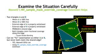
![67
Solution: Triangle A Claims Coverage or B Claims,
But not Both
void main() {
gl_FragColor = gl_Color;
}
#version 400 compatibility
#extension GL_NV_sample_mask_override_coverage : require
layout(override_coverage) out int gl_SampleMask[];
const int num_samples = 16;
const int all_sample_mask = 0xffff;
void main() {
gl_FragColor = gl_Color;
if (gl_SampleMaskIn[0] == all_sample_mask) {
gl_SampleMask[0] = all_sample_mask;
} else {
int mask = 0;
for (int i=0; i<num_samples; i++) {
vec2 st;
st = interpolateAtSample(gl_TexCoord[0].xy, i);
if (all(lessThan(abs(st),vec2(1))))
mask |= (1 << i);
}
int otherMask = mask & ~gl_SampleMaskIn[0];
if (otherMask > gl_SampleMaskIn[0])
gl_SampleMask[0] = 0;
else
gl_SampleMask[0] = mask;
}
}
Handle in fragment shader: by overriding the sample mask coverage
BEFORE: Simply output interpolated color AFTER: Interpolate color + resolve overlapping coverage claims
trivial
fragment shader](https://image.slidesharecdn.com/tz1z7aomq7awcfmdvqcg-signature-2116a99f130611e1d920f73a25e85ccaa3981fd57edb2917daa913d8104eb9ea-poli-161004030516/85/NVIDIA-OpenGL-in-2016-67-320.jpg)
![68
Solution: Triangle A Claims Coverage or B Claims,
But not Both
void main() {
gl_FragColor = gl_Color;
}
#version 400 compatibility
#extension GL_NV_sample_mask_override_coverage : require
layout(override_coverage) out int gl_SampleMask[];
const int num_samples = 16;
const int all_sample_mask = 0xffff;
void main() {
gl_FragColor = gl_Color;
if (gl_SampleMaskIn[0] == all_sample_mask) {
gl_SampleMask[0] = all_sample_mask;
} else {
int mask = 0;
for (int i=0; i<num_samples; i++) {
vec2 st;
st = interpolateAtSample(gl_TexCoord[0].xy, i);
if (all(lessThan(abs(st),vec2(1))))
mask |= (1 << i);
}
int otherMask = mask & ~gl_SampleMaskIn[0];
if (otherMask > gl_SampleMaskIn[0])
gl_SampleMask[0] = 0;
else
gl_SampleMask[0] = mask;
}
}
Handle in fragment shader: by overriding the sample mask coverage
BEFORE: Simply output interpolated color AFTER: Interpolate color + resolve overlapping coverage claims
additional
re-rasterization epilogue
early
accept
optimization
sample mask override coverage
support](https://image.slidesharecdn.com/tz1z7aomq7awcfmdvqcg-signature-2116a99f130611e1d920f73a25e85ccaa3981fd57edb2917daa913d8104eb9ea-poli-161004030516/85/NVIDIA-OpenGL-in-2016-68-320.jpg)


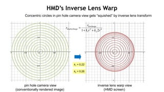
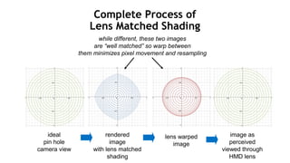
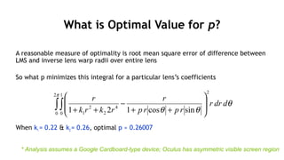
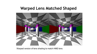
![82
Pin-hole Camera Image Assumptions
•Assume a conventionally rendered perspective image
• In other words a pin-hole camera image
•r is the distance of a pixel (x,y) relative to the center of the image at
(0,0) so
•Theta is the angle of the pixel relative to the origin
•Assume pin hole camera image has maximum radius of 1
• So the X & Y extent of the images is [-1..1]
22
yxr +=
θ
θ
sin
cos
ry
rx
=
=](https://image.slidesharecdn.com/tz1z7aomq7awcfmdvqcg-signature-2116a99f130611e1d920f73a25e85ccaa3981fd57edb2917daa913d8104eb9ea-poli-161004030516/85/NVIDIA-OpenGL-in-2016-82-320.jpg)


![105
Straightforward API
• glWindowRectanglesEXT(GLenum mode, GLsizei count, const GLint rects[]);
• mode can be either GL_INCLUSIVE_EXT or GL_EXCLUSIVE_EXT
• count can be from 0 to maximum number of supported window rectangles
• Must be at least 4 (for AMD hardware)
• NVIDIA hardware supports 8
• Rectangles allowed to overlap and/or disjoint
• Each rectangle is (x,y,width,height)
• width & height must be non-negative
• Initial state
• GL_EXCLUSIVE_NV with zero rectangles
• Excluding rendering from zero rectangles means nothing is discarded by window
rectangles test
Multi-vendor EXT_window_rectangles Extension](https://image.slidesharecdn.com/tz1z7aomq7awcfmdvqcg-signature-2116a99f130611e1d920f73a25e85ccaa3981fd57edb2917daa913d8104eb9ea-poli-161004030516/85/NVIDIA-OpenGL-in-2016-105-320.jpg)


![111
OpenGL Extensions Used in LMS VR Pipeline
• Allows vertex shader to output two clip-space
positions
• (x1,y,z,w) and (x2,y,z,w)
• Results in TWO primitives
one for left eye & one for right eye
• New GLSL built-ins
• gl_SecondaryPositionNV
• Like gl_Position but for “second eye’s view”
• gl_SecondaryViewportMaskNV[]
• Like gl_ViewportMaskNV[] but for “second eye’s
view”
• Also can steer primitives to different texture
array slices
• layout(secondary_view_offset = 1) int gl_Layer;
Pascal’s NV_stereo_view_rendering Extension](https://image.slidesharecdn.com/tz1z7aomq7awcfmdvqcg-signature-2116a99f130611e1d920f73a25e85ccaa3981fd57edb2917daa913d8104eb9ea-poli-161004030516/85/NVIDIA-OpenGL-in-2016-111-320.jpg)


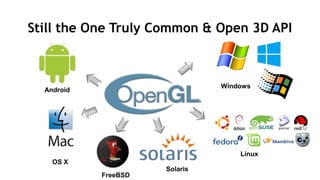
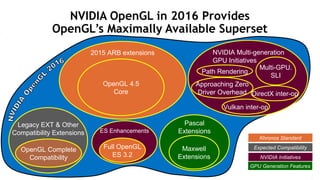
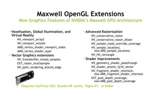
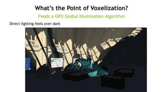
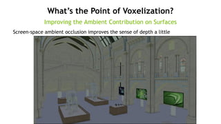
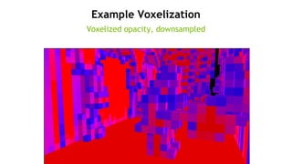
Mark Kilgard discusses advancements and features of OpenGL at SIGGRAPH 2016, highlighting the evolution of the API and its support for modern graphics programming. Key topics include the introduction of new extensions, debugging tools, and features aimed at enhancing virtual reality graphics. The presentation covers recent developments in NVIDIA's GPU architecture, alongside specific examples of using OpenGL for efficient rendering across different platforms.

![[Ndc11 박민근] deferred shading](https://cdn.slidesharecdn.com/ss_thumbnails/ndc11deferredshading-110602220043-phpapp01-thumbnail.jpg?width=640&height=640&fit=bounds)