Downloaded 85 times
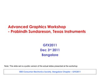
![GFX2011 8.30 AM [Registration and Introduction, Equipment setup] 9.00 AM Why Graphics ? Present and Future – Prof. Vijay Natarajan, Assistant Professor, Department of Computer Science and Automation, IISc, Bangalore 9.45 AM Introduction to the OpenGL/ES Rendering pipeline, and algorithms Detailed walkthrough of the OpenGL ES2.0 spec and APIs – Part 1 1.00 PM [Lunch] Detailed walkthrough of the OpenGL ES2.0 spec and APIs – Part 2 - Break - Framework and platform integration - EGL, Android (SurfaceFlinger) Tools for performance benchmarking, and Graphics Development Q&A, Certificate presentation to participants – Networking](https://image.slidesharecdn.com/gfx2011public-111222222304-phpapp01/85/Advanced-Graphics-Workshop-GFX2011-2-320.jpg)


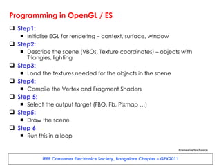


![Lab 94 – Texturing (Keys to remove errors) var indexArray = new Uint16Array([0, 1, 2, 2 , 1, 3]); var texCoordArray = new Float32Array([0,0, 10 ,0, 0, 10, 10,10]); context.enableVertexAttribArray( 1 ); context.vertexAttribPointer(1, 2 , context.FLOAT, context.FALSE, 0, 0);](https://image.slidesharecdn.com/gfx2011public-111222222304-phpapp01/85/Advanced-Graphics-Workshop-GFX2011-37-320.jpg)


![Lab 96 – Keys for “Squishing the slice” uniform mediump float skyline; vec4 tempPos; tempPos = MVPMatrix * inVertex; tempPos.y=min(skyline, tempPos.y); //or, try below – one of the 2 tempPos.y=min(sin(inVertex.x*5.0)+cos(inVertex.y*2.0), tempPos.y); gl_Position = tempPos; var skylineLoc = context.getUniformLocation(sprogram,"skyline"); context.uniform1f(skylineLoc, -0.1); context.drawArrays(context.TRIANGLES, 0, vertexparams[1 ] /3 );](https://image.slidesharecdn.com/gfx2011public-111222222304-phpapp01/85/Advanced-Graphics-Workshop-GFX2011-62-320.jpg)


The document outlines the agenda for an Advanced Graphics Workshop being held by Texas Instruments. The workshop will include an introduction to graphics hardware architectures and the OpenGL rendering pipeline. It will provide a detailed walkthrough of the OpenGL ES 2.0 specification and APIs. Participants will work through several hands-on labs covering texturing, transformations, shaders and more. The goal is to help developers optimize graphics performance on embedded platforms.