Download to read offline
![International Research Journal of Engineering and Technology (IRJET) e-ISSN: 2395-0056
Volume: 06 Issue: 07 | July 2019 www.irjet.net p-ISSN: 2395-0072
© 2019, IRJET | Impact Factor value: 7.34 | ISO 9001:2008 Certified Journal | Page 1369
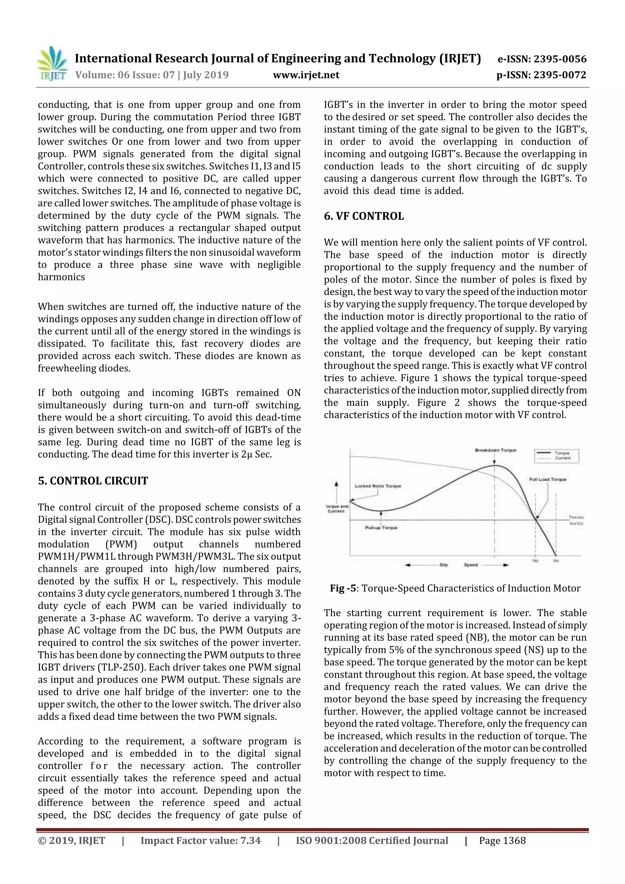
Fig -6: Torque-Speed Characteristics of Induction Motor
with VF Control
7. CONCUSION
Hence the modern world which seeks a renewable energy
source for the electricity requires the concept of power
which can be achieved using the concept of VFD control for
the speed control of 3-phase induction motors.AVF solution
can be implemented using Variable Frequency Drive with
PWM technique is suitable for crisp control of motors. In
industries where motors and pumps used to satisfy all basic
necessities can used the VFD controlled motors lead to
higher energy saving. Also the additional resources used
along with VFD like timers and run lamps provide greater
safety and security measures against sudden jerk in current
and voltage
REFERENCES
[1] R.Krishnan, Electric Motor Drives (Modeling,
Analysis, and Control), Prentice Hall, Inc. 2001.
[2] Ned Mohan, Torre M. Undeland, WilliamP.Robbins,
Power Electronics Converters, Applications and
Design, Wiley, New York. 1995.
[3] Richard Valentine, Motor Control Electronic
Handbook, McGraw-Hill, New York, 1998.
[4] Sigh, M. D. and Khanchandani, K. B. Power
Electronic, Tata McGraw-Hill Publishing Company
Limited, New Delhi, 2000.
[5] Ham N. J., Hammerton C. J. and Sharples. D.Power
Semiconductor Applications, Tata McGraw-Hill
Publishing Company Limited, New Delhi.
[6] S. U. Hassan and H. B. Akram, “Speed and frequency
control of AC induction motor using variable
frequency drive,” Student Research Paper
Conference, vol. 2, no. 56, pp. 272-279, 2015.
[7] M. H. Rashid, Power Electronics: Circuits, Devices
and Applications. New York: Pearson Publications,
2013.
[8] Variable Frequency Drive. (2017). PWM Variable
Frequency Drive Characteristics.
[9] M. H. Rashid, Power Electronics: Circuits, Devices
and Applications. New York: Pearson
Publications, 2013.[12] P. S. Bhimbhra, Power
Electronics: Phase Controlled Rectifiers and
Inverters. Delhi: Khanna Publishers, 2004.](https://image.slidesharecdn.com/irjet-v6i7483-191121085956/75/IRJET-Phase-Conversion-of-VFD-based-Induction-Motor-4-2048.jpg)

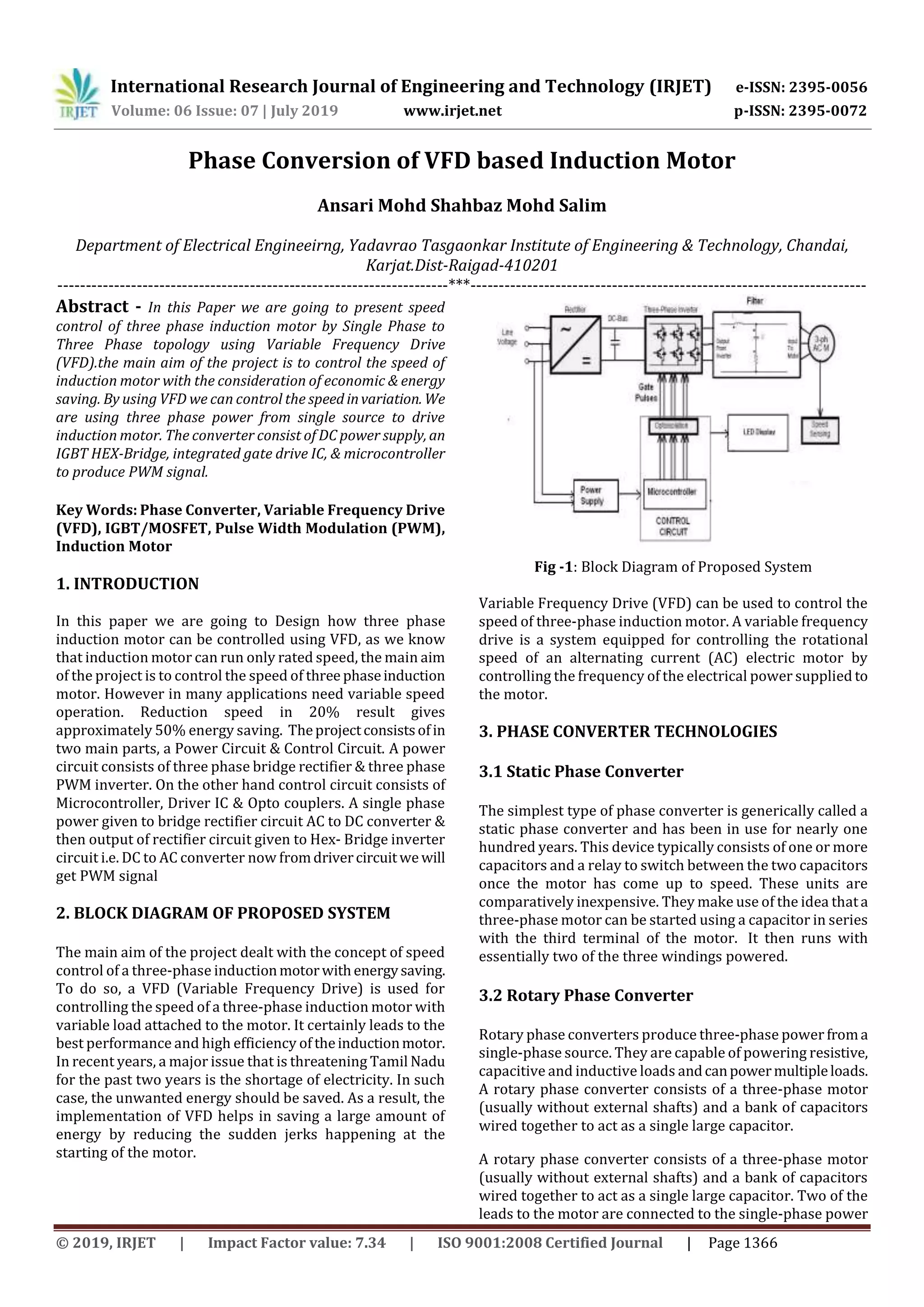
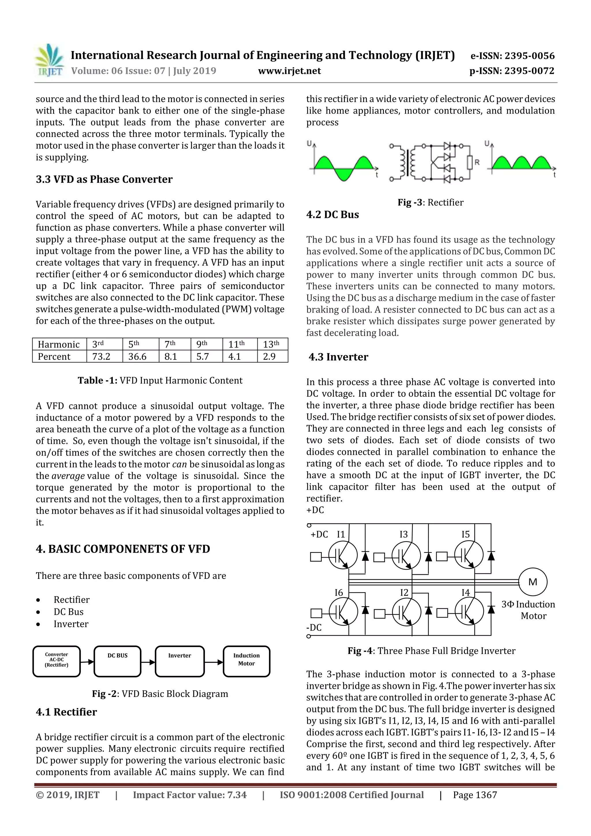
This document discusses using a variable frequency drive (VFD) to control the speed of a three-phase induction motor. A VFD allows the motor to operate at variable speeds, which can provide energy savings compared to operating at a single rated speed. The VFD converts incoming single-phase power to three-phase power using a rectifier to produce DC power, then an inverter uses pulse width modulation to generate a three-phase AC output that can be varied in frequency to control motor speed. This setup allows flexible control of the induction motor's speed while improving efficiency over constant speed operation.