Download to read offline
![International Research Journal of Engineering and Technology (IRJET) e-ISSN: 2395-0056
Volume: 06 Issue: 06 | June 2019 www.irjet.net p-ISSN: 2395-0072
© 2019, IRJET | Impact Factor value: 7.211 | ISO 9001:2008 Certified Journal | Page 3717
SPEED CONTROL AND MINIMIZATION OF TORQUE RIPPLES IN BLDC
MOTOR USING PI, SMC AND SMC-PWM TECHNIQUES
Mr. S. BALA MURALI 1,K. PUSHPALATHA 2, Dr. P.MALLIKARJUNA RAO 3
1Associate professor, Department of Electrical and Electronics Engineering, ANITS (A), Visakhapatnam, India
2M.Tech Student (Control Systems Engineering) EEE, ANITS (A), Visakhapatnam, India
3Professor, Department of Electrical Engineering, AU College of Engineering (A), Visakhapatnam, India
---------------------------------------------------------------------***----------------------------------------------------------------------
Abstract - Brushless DC motors Controlled through
electronic commutation whose motor position is sensed using
Hall Sensors. In this paper, initially the responses of BLDC
motor are observed by using PI and SMC Controllers. The
Sensitivity of PI towards the constraint variations and
unexpected torque disturbances, PI Controller replaced with
Sliding Mode Controller (SMC). SMC is an effective synthesis
technique for Non-Linear uncertain systems with fast and
robust transient responses. This paper deals with a new
control technique based on PWM control of brushless DC
motor (BLDC). PWM technique is broadly used in motors
which are controlled using power converters. Also it controls
analog systems with digital processing outputs.
Key Words: BLDC, Sliding Mode Control (SMC), PWM,
Matlab Simulink.
1. INTRODUCTION:
A brushless DC motor (BLDC) is a PMSM motor with
trapezoidal back emf and electronically commutated
system [1]. The permanent magnet synchronous motors
(PMSM) have the advantage of high efficiency, high torque
density, less volume and less maintenance which are
satisfied with EV accurate necessities [2-3]. BLDC motors
have less noise and large durability. The main advantage of
this motor is that it can be controlled by using feedback
mechanisms for faster speed responses and less ripples in
torque. In conventional PI controller, the motor
performance may result disturbances in torque due to
variations in parameters and its sensitivity towards the
uncertainty nature of the system. In order to conquer this
disadvantage, Sliding mode control (SMC) is adopted.
Generally the practical BLDC motor is non linear and there
are number of disturbances, to overcome these
disadvantages and to improve the performance of motor
SMC is adopted. Even though SMC is vigorous to changes
that occur in motor, the increment of gains which is used
for controlling purpose causes chattering effect which is
not desirable and causes ripples in the responses and also
results high frequency switching in converters.
To overcome these disadvantages PWM technique with SMC
controllers is implemented in this paper. PWM technique
encodes the analog value to digital values by controlling
duty cycle
The method of implementing SMC controller:
1. Initially observing the convergence and setting of the
control law.
2. Later establish the sliding mode at the initial time to
give the robust behaviour of the implemented control law
all over the system response.
3. The making of the path enabling the convergence in finite
time [5], [6].
In this work overview of control of BLDC motor using PI
controller and sliding mode control is observed. Later the
control of motor with SMC PWM technique is observed. The
results obtained in simulation and a conclusion where we
emphasize the interest of this method of control.
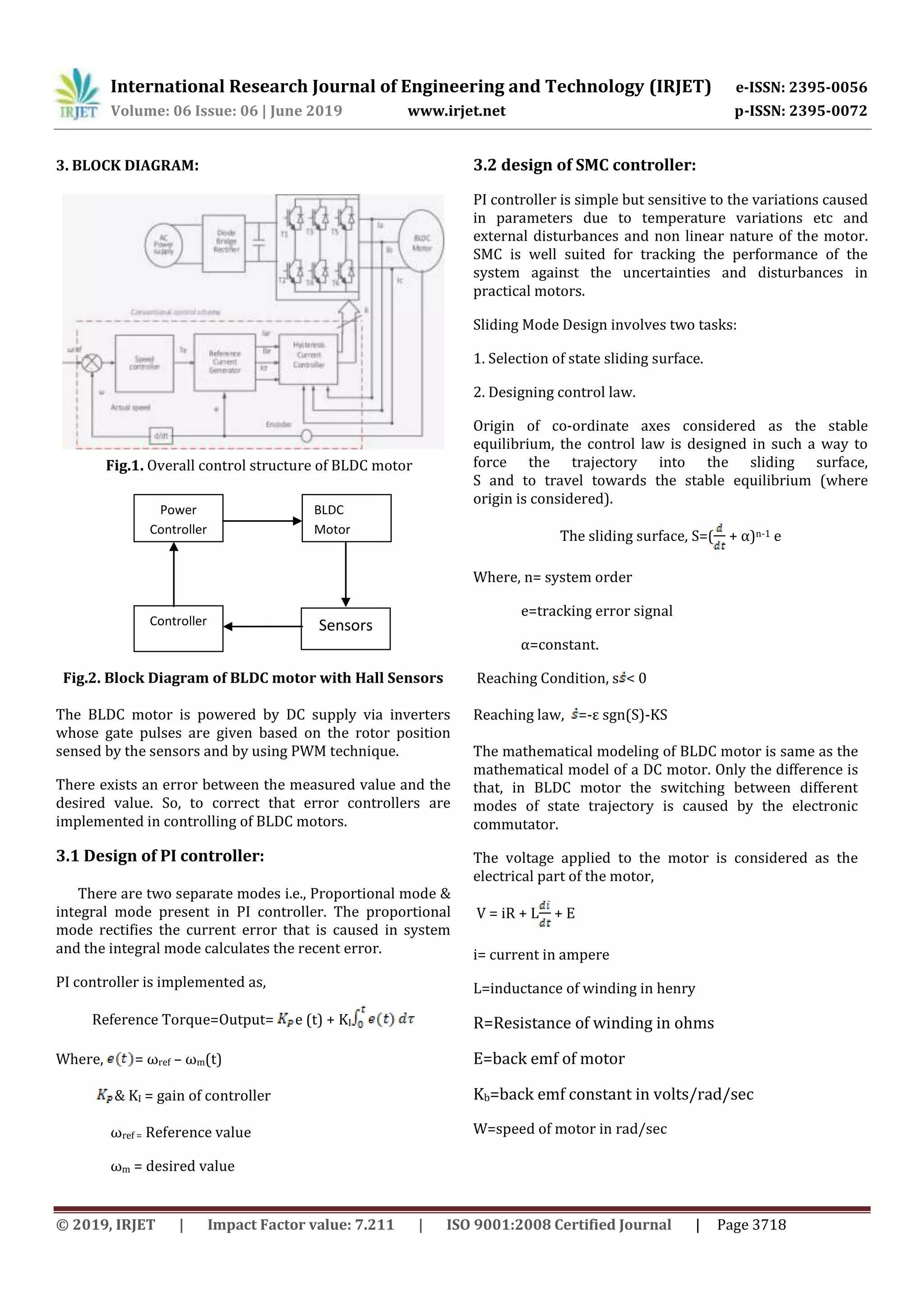
2. CONTROL OF BLDCMOTOR
The control methods of DC motor are divided into two
categories. One of them is scalar control which the required
speed of motor is obtained by controlling the stator voltage
amplitude and frequency. This method is suitable for the
constant loads but it is not applicable for the motors with
the dynamical varying loads. And the other is vector control
which has the best dynamic responses.
Controlling the motor simply by varying the supply voltage
is the open loop control of the motor. In order to overcome
the external disturbances and deviation from the required
results and the torque ripples closed loop control is
implemented. This is obtained by using the sensors which
senses the output of the motor, controller and PWM circuit
to generate the pulses to the inverter for proper flow of
current to the each phase windings.](https://image.slidesharecdn.com/irjet-v6i6746-191218071725/75/IRJET-Speed-Control-and-Minimization-of-Torque-Ripples-in-BLDC-Motor-using-Pi-SMC-and-SMC-PWM-Techniques-1-2048.jpg)
![International Research Journal of Engineering and Technology (IRJET) e-ISSN: 2395-0056
Volume: 06 Issue: 06 | June 2019 www.irjet.net p-ISSN: 2395-0072
© 2019, IRJET | Impact Factor value: 7.211 | ISO 9001:2008 Certified Journal | Page 3719
=(-E- iR + V)
Mechanical part of model obtained as,
T= J + Bw + TL
T=Torque in Newton-Meter
J=moment of inertia
TL=disturbance input
= (- Bw +T-TL)
Block diagram of SMC consists two loops. One controller is
current loop and the other is for speed loop.
Fig.3. Overall block diagram of SMC with BLDC motor
For inner current loop,
V=L[α sgn (S1) + ρS1 + ] +E+( - e1)R
Where, α & ρ are constants,
e1 is the current error signal,
S1 is SMC controller for current loop.
i.e. S1= e1= – i
For over loop,
T= J [ϒ sgn(S2) + ζ S2 + ]+ TL + ( - e2) B
Where ϒ& ζ are constants,
e2 is speed error signal,
S2 is SMC controller for speed loop
i.e. S2= e2 = – ω
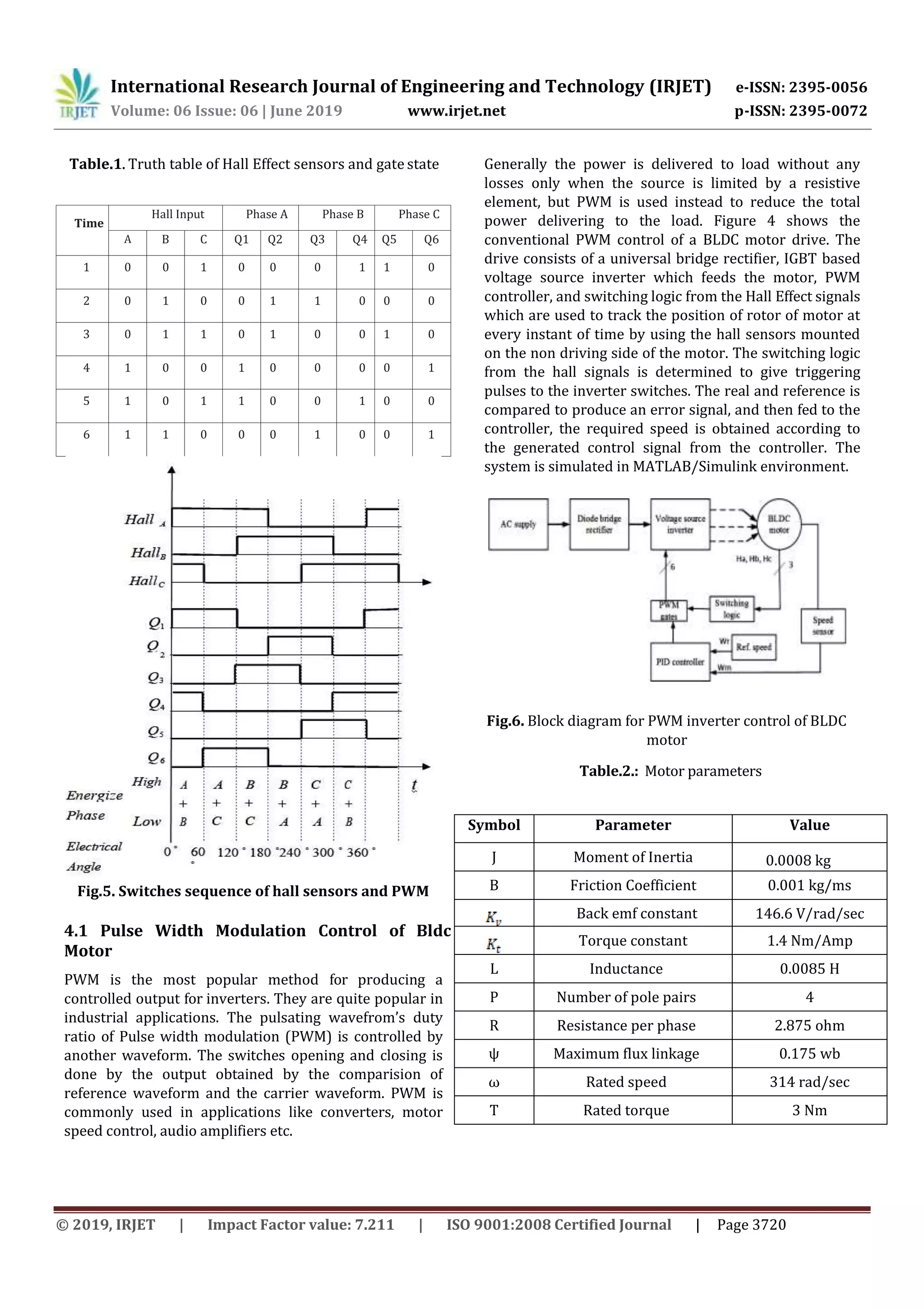
4. PROCEDURE OF THE CONTROL SYSTEM DESIGN
Control of system require four feedback signals, which are
three rotor position sensed signals and speed of the motor.
The speed error is obtained by comparing the sensed
motor speed which is given as feedback and the required
speed. The error signal thus obtained is given to speed
controller. The output of this controller is the torque. By
using the torque constant the reference current is derived.
This current is compared with the currents obtained at the
rotor. This error is given to the another loop caller current
controller loop resulting the voltage as output. This voltage
obtained is given to the universal bridge. The speed of the
motor can be controlled by varying this voltage. There are
six switches in this universal bridge as shown in fig 4. The
device is protected from the reverse voltages by using the
freewheeling diodes across each switch in the universal
bridge. Three switches among the six switches are
considered as one group, thus creating positive group and
negative group. The switches S1, S3, S5 are considered as
positive group and the switches S4, S6, S2 are divided as
negative group. When the switches are turned on and off
the power is controlled and flows to the load. The switching
between the group of switches in the universal bridge is
created by regulating the gate pulses of the bridge. These
gate pulses are controlled by the signals obtained by using
the hall sensors and the PWM technique as shown in Figure
5. The voltage vector of BLDC motor is separated into six
sectors, which is just a one-to-one Switches Sequence
and Pulse Width Modulation. Table I. shows the switches
sequence to be followed [5-6]. The current to the each
phase winding flows corrects by the proper switching
sequence between the switches. As the six timing
sequences, the trapezoidal control also called six steps
control. In this method, the PWM applied on high side and
lower side, the duty cycle of PWM controls the magnitude
of the current flows to the controller, and the spinning of
BLDC motor becomes fast by increasing the width of the
PWM duty.
Fig.4. Three-phase bridge inverter consists of six
IGBTs switches](https://image.slidesharecdn.com/irjet-v6i6746-191218071725/75/IRJET-Speed-Control-and-Minimization-of-Torque-Ripples-in-BLDC-Motor-using-Pi-SMC-and-SMC-PWM-Techniques-3-2048.jpg)
![International Research Journal of Engineering and Technology (IRJET) e-ISSN: 2395-0056
Volume: 06 Issue: 06 | June 2019 www.irjet.net p-ISSN: 2395-0072
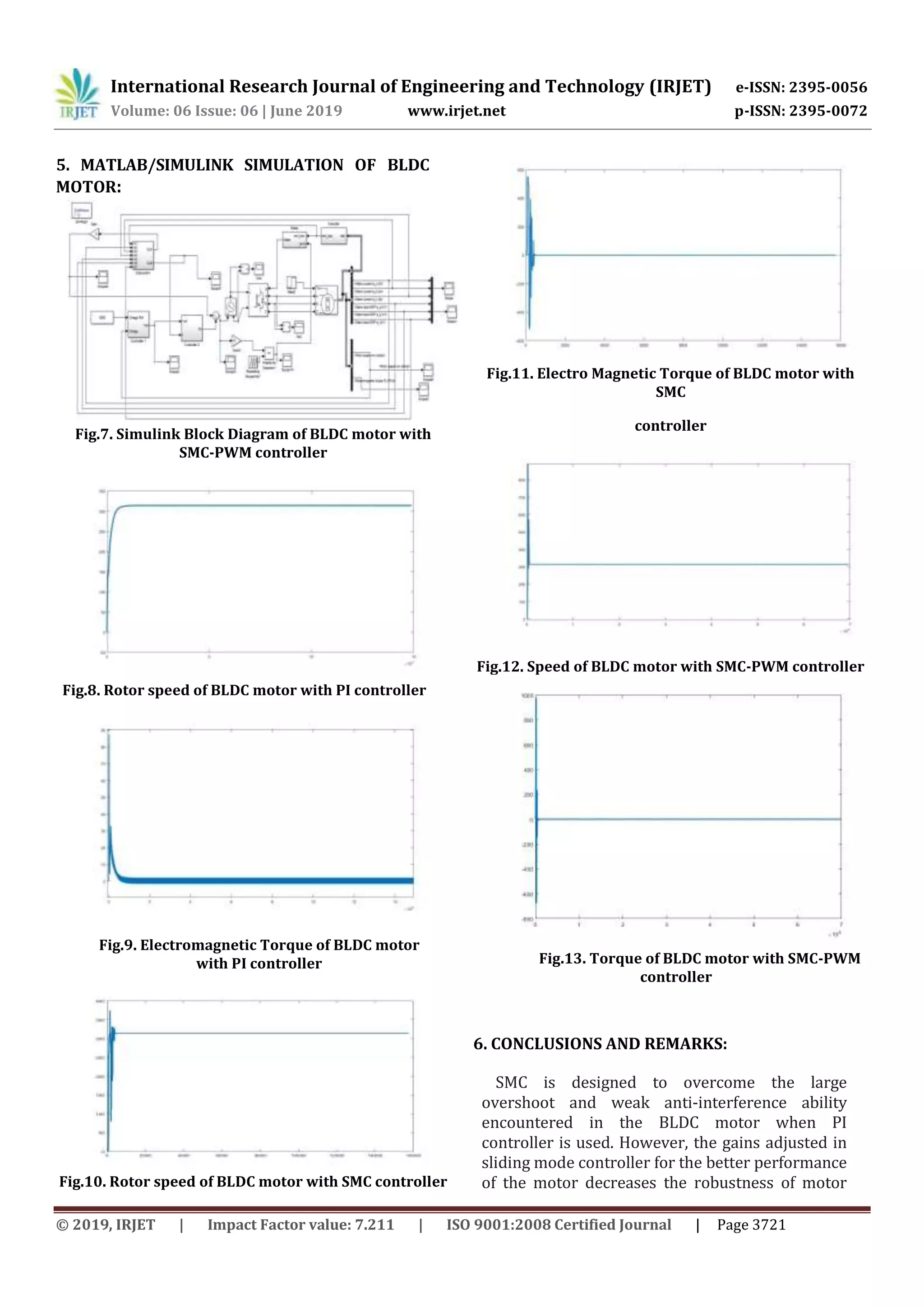
© 2019, IRJET | Impact Factor value: 7.211 | ISO 9001:2008 Certified Journal | Page 3722
and increase the chattering effective in motor.
Comparative simulation experiments are
performed and simulation results are analyzed
respectively. The simulation results obtained by
using the traditional sliding mode controller are
better than the PI controller results, but the
proposed technique in this paper is better than
the traditional SMC as it improves the robustness
of the motor and reduces the chattering effect
compared to prior techniques. High efficiency,
high performance of BLDC motor can be realized
using SMC-PWM technique. The ripples in the
torque for different loading condition are reduced.
The proposed method reduces the torque ripples
produced due to the flow of motor currents
through the freewheeling diodes during the
commutation intervals and obtains the faster
speed responses.
REFERENCES:
[1] Brushless Permanent Magnet Motor Design Second
Edition Dr. Duane Hanselman Electrical and
Computer Engineering University of Maine Orono,
ME 04469 USA
[2] S.Balamurali, P.Mallikarjuna Rao, “Adaptive sliding
mode control of BLDC motor using Cuckoo search
algorithm”, 2nd international conference on Inventive
systems, 2018.
[3] Bindeshwar Singh, S. P. Singh, Ravi Chaurasia,
Jaswant Singh and Sulabh Sachan“Perfomance
investigation of Permanent magnet syn- chronous
motor drive using vector controlled technique”,
IEEE,2nd International Conference on Power, Control
and Embedded Systems, 2012
[4] Munje, R.K., Road, M.R., & Kushare, B.E. (2010).
Speed control of DC motor using PI and SMC. 2010
conference.
[5] J. Gao and J. Kang, “Modeling and simulation of
pennanent magnet synchronous motor vector
control”, Information Technology Journal,vo!. 13, no.
3, pp. 578-582, Feb., 2014.
[6] Hoang Le-Huy, Robert Perret, Rene Feuillet,
“Minimization of torque ripple in Brushless DC
motor drive”, IEEE Transactions on Industry
Applications (Volume: IA-22, Issue: 4,July 1986)](https://image.slidesharecdn.com/irjet-v6i6746-191218071725/75/IRJET-Speed-Control-and-Minimization-of-Torque-Ripples-in-BLDC-Motor-using-Pi-SMC-and-SMC-PWM-Techniques-6-2048.jpg)

This document discusses speed control and minimization of torque ripples in BLDC motors using PI, SMC, and SMC-PWM control techniques. It begins by observing the responses of a BLDC motor using PI and SMC controllers. SMC is adopted to overcome the sensitivity of PI controllers to parameter variations and disturbances. A new control technique based on PWM control of BLDC motors is also presented. Simulation results are used to compare the performance of PI, SMC, and SMC-PWM control methods. SMC-PWM control is found to improve motor performance while reducing torque ripples and switching frequency fluctuations.