Download to read offline


![.
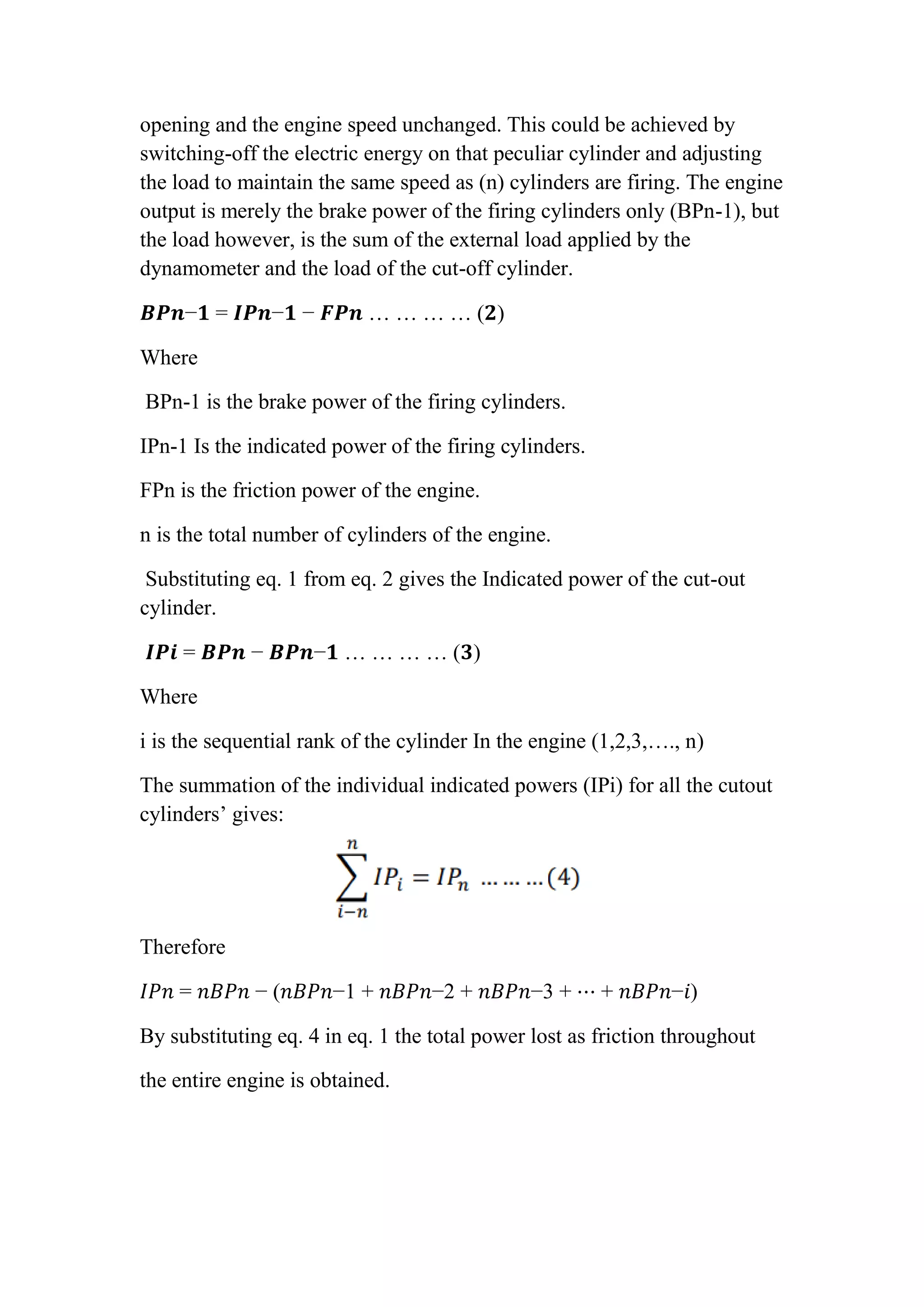
Discussion:
1- What is the difference between the Indicated power and the brake
power?
Indicated power measures the power developed on top of the pistons.
Brake power measures the power developed at the output of the
crankshaft. The indicated power is larger than the brake power by an
amount equal to the friction power.
2- What are the reasons for the fluctuations in the output of different
cylinders? (1) Abrasion due to foreign particles in the oil film. (2)
Erosion due to metal contact between the pistons or rings and the cylinder
bore. (3) Corrosion - oxidization or chemical action of the cylinder wall
by the products of combustion.
3- Why engine speed should remain constant throughout the test? The
purpose of Morse Test is to obtain the approximate Indicated Power of a
Multi-Cylinder Engine. It consists of running the engine against a
dynamometer at a particular speed, cutting out the firing of each cylinder
in turn and noting the fall in BP each time while maintaining the speed
constant.
4- What is the pumping work? the pumping work is defined as the work
in the exhaust and intake strokes. It is difficult to define pumping work in
two-stroke engines due to the lack of these two pumping strokes.
5- What are the motoring losses? (1)Mechanical losses: As their name
suggests, mechanical losses are caused by movement of the motor.
(2)Magnetic losses: These losses are associated with magnetic paths of
the motor. (3)Brush losses: During commutation, some losses occur
between the commutator and the brushes.
6- Plot engine IP, BP, FP in [kw], T in [N.m] and nm [%] versus engine
speed N in [rpm).](https://image.slidesharecdn.com/morsetestrawa-211027191857/75/Morse-test-r-9-2048.jpg)
![Reference:
[1] Anyebe, E.A (2009). Combustion Engine and Operations, Automobile
Technology Handbook. 2.
[2] Heywood, J. (2018). Internal Combustion Engine Fundamentals 2E.
McGraw-Hill Education. ISBN 978-1-260-11611-3.
[3] Nunney, Malcolm J. (2007). Light and Heavy Vehicle Technology
(4th ed.). Elsevier Butterworth-Heinemann. ISBN 978-0- 7506-8037-0.
[4]"Ingersoll Rand Engine Starting – Turbine, Vane and Gas Air
Starters". Ingersoll Rand. Archived from the original on 2016-09-13.
Retrieved 2016-09-05.](https://image.slidesharecdn.com/morsetestrawa-211027191857/75/Morse-test-r-10-2048.jpg)

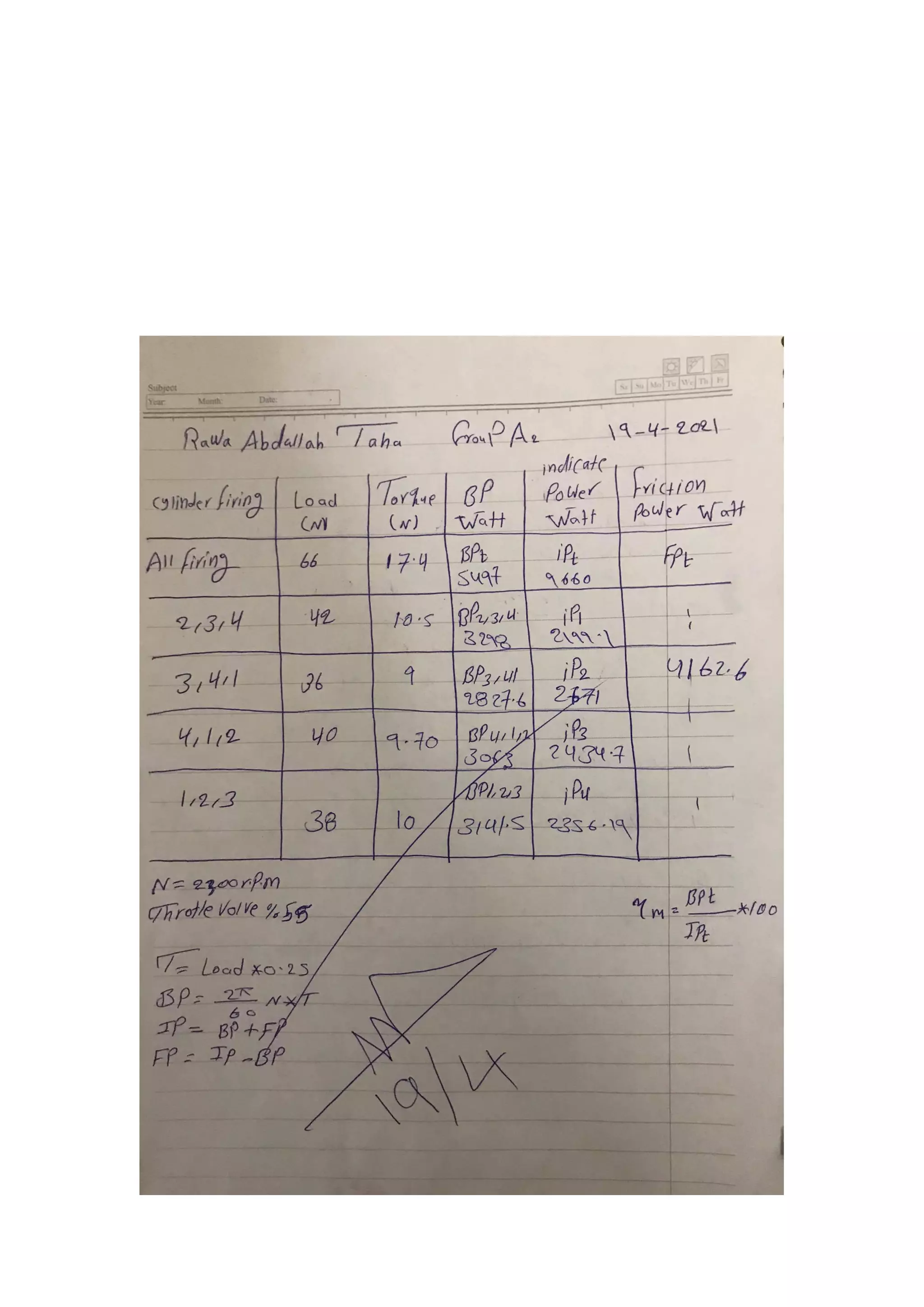
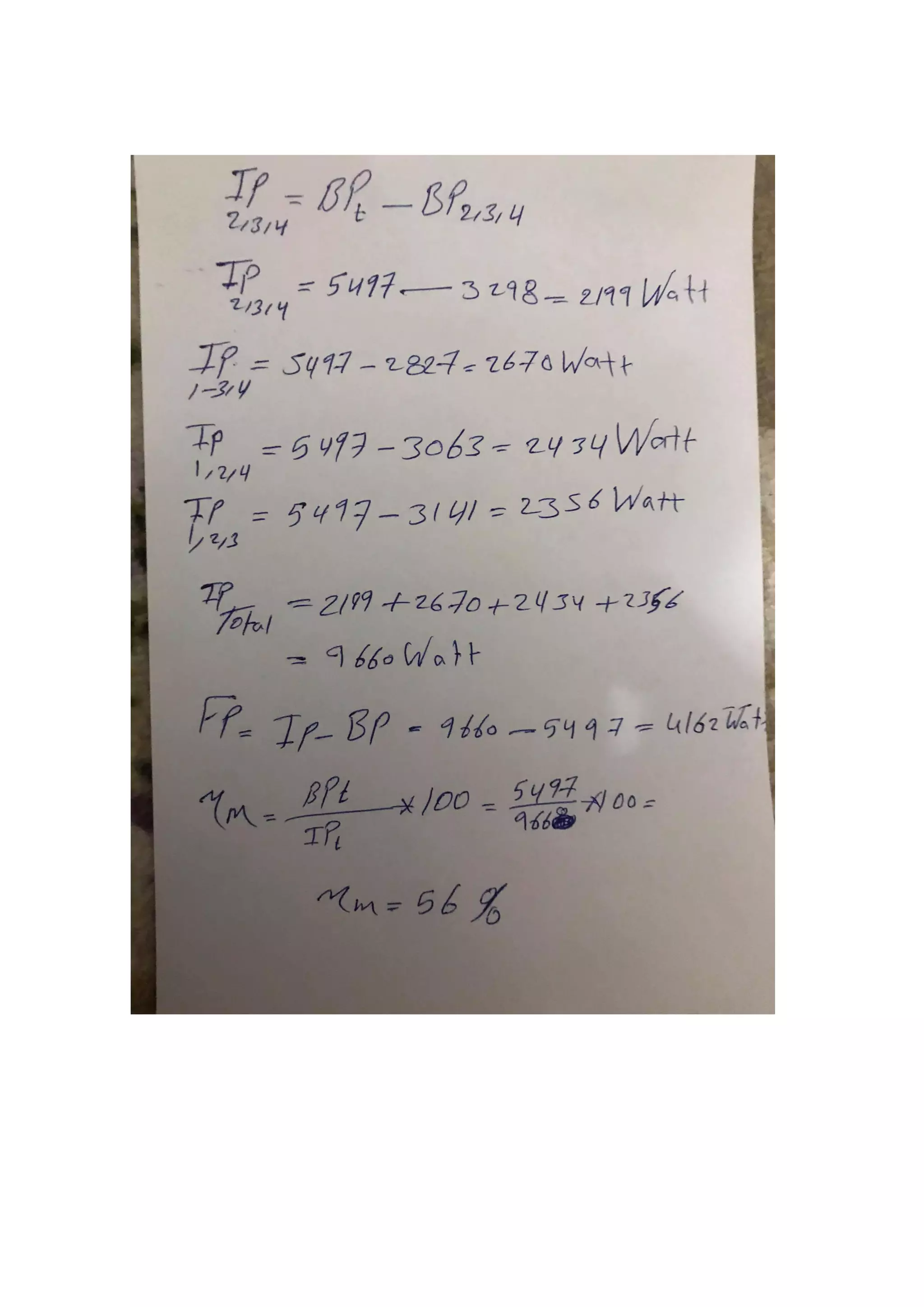
This document describes a Morse test conducted on an internal combustion engine to determine the engine's indicated power (IP), brake power (BP), and friction power (FP). The test involves running the engine at a constant speed and cutting the ignition to individual cylinders while adjusting the load to maintain speed. The difference in BP readings gives the IP of the cut cylinder. Summing the IP values yields the engine's total IP. Subtracting BP from IP provides FP, and the ratios of these values can be used to calculate mechanical efficiency. The objectives, conditions, introduction, theory, procedure, calculations, discussion and references related to the Morse test are detailed in the document.
Introduction of the Morse Test, student details, and academic information.
Objectives to determine indicated and friction power using a multi-cylinder engine and dynamometer. Theoretical aspects include calculations of power in relation to engine speed.
Step-by-step procedure to conduct the Morse Test, detailing how to record data for each cylinder.
Discussion on differences between indicated power and brake power, fluctuations in cylinder output, and the importance of consistent engine speed during testing.
List of references for further reading on combustion engines and relevant technical literature.


