The document presents a study on controlling the speed of a separately excited DC motor under varying load conditions using a PID controller. Simulations conducted in MATLAB Simulink demonstrate that the PID controller effectively maintains motor speed regardless of load disturbances, achieving only minor fluctuations during operation. The study concludes that employing PID control is proven to be an effective method for achieving desired motor speed stability in industrial applications.
![Muhammad Rafay Khan, Aleem Ahmed Khan & Umer Ghazali
International Journal of Engineering (IJE), Volume (9) : Issue (3) : 2015 38
Speed Control of DC Motor under Varying Load Using PID
Controller
Muhammad Rafay Khan engr.muhammad.rafay@gmail.com
Electronic Engineering Department
Sir Syed University of Engineering & Technology
Karachi, 75300, Pakistan
Aleem Ahmed Khan aaleem.engineer@gmail.com
Electronic Engineering Department
Sir Syed University of Engineering & Technology
Karachi, 75300, Pakistan
Umer Ghazali umerghazali3@gmail.com
Electronic Engineering Department
Sir Syed University of Engineering & Technology
Karachi, 75300, Pakistan
Abstract
DC motors are used extensively in industrial variable speed applications because of most
demanding speed-torque characteristics and are simple in controlling aspects. This paper
presents a DC motor speed controlling technique under varying load condition. The linear system
model of separately excited DC motor with Torque-variation is designed using PID controller. A
Matlab simulation of proposed system with no-Load and full-load condition is performed on
Simulink platform to observe the system response. The motor speed is kept constant in this
experiment. The simulation result of the experiment shows that a motor is running approximately
at a constant speed regardless of a motor load. The Simulink results show that the speed of the
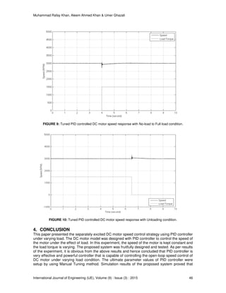
motor is slow down only for about 270 rpm (9%) in 980 milliseconds under the effect of full load.
However, the motor speed is hunting about 200 rpm (6.66%) in 900 milliseconds on unloading
condition. It is concluded that a PID controller is successful tool for controlling the motor speed in
presence of load disturbances.
Keywords: Speed Control, DC Motor Model, PID Control, Closed Loop, Load Disturbance.
1. INTRODUCTION
For the last many years, the DC motors are extensively used in the industrial control applications.
DC motors are highly versatile and flexible in aspects of speed control. High performance DC
motor drives are popular in industrial applications for its enormous good characteristics such as
high starting, accelerating and retard torque, high response performance, rapid braking and
easier to be linear control etc. DC motor is a highly controllable electrical actuator and is widely
used for robotic manipulators, guided vehicles, steel rolling mills, cutting tool, overhead cranes,
electrical traction and other application etc. In comparison to AC drive, DC motor drives are
simple and less expensive [1].
Mostly, the feedback control loop is indispensable for the desired and better performance of the
system. However, this feedback system has slow response. For the fast dynamic response of the
system, many control strategies have been deployed in various feedback control systems. The
vital role of controls in a drive system include precise and quick tracking for reference speed with
minimum overshoot or undershoot and having little or eliminated steady state error. The
conventional (proportional integral- derivative).PID controllers have become very popular and](https://image.slidesharecdn.com/ije-485-151214124940/85/Speed-Control-of-DC-Motor-under-Varying-Load-Using-PID-Controller-1-320.jpg)
![Muhammad Rafay Khan, Aleem Ahmed Khan & Umer Ghazali
International Journal of Engineering (IJE), Volume (9) : Issue (3) : 2015 38
Speed Control of DC Motor under Varying Load Using PID
Controller
Muhammad Rafay Khan engr.muhammad.rafay@gmail.com
Electronic Engineering Department
Sir Syed University of Engineering & Technology
Karachi, 75300, Pakistan
Aleem Ahmed Khan aaleem.engineer@gmail.com
Electronic Engineering Department
Sir Syed University of Engineering & Technology
Karachi, 75300, Pakistan
Umer Ghazali umerghazali3@gmail.com
Electronic Engineering Department
Sir Syed University of Engineering & Technology
Karachi, 75300, Pakistan
Abstract
DC motors are used extensively in industrial variable speed applications because of most
demanding speed-torque characteristics and are simple in controlling aspects. This paper
presents a DC motor speed controlling technique under varying load condition. The linear system
model of separately excited DC motor with Torque-variation is designed using PID controller. A
Matlab simulation of proposed system with no-Load and full-load condition is performed on
Simulink platform to observe the system response. The motor speed is kept constant in this
experiment. The simulation result of the experiment shows that a motor is running approximately
at a constant speed regardless of a motor load. The Simulink results show that the speed of the
motor is slow down only for about 270 rpm (9%) in 980 milliseconds under the effect of full load.
However, the motor speed is hunting about 200 rpm (6.66%) in 900 milliseconds on unloading
condition. It is concluded that a PID controller is successful tool for controlling the motor speed in
presence of load disturbances.
Keywords: Speed Control, DC Motor Model, PID Control, Closed Loop, Load Disturbance.
1. INTRODUCTION
For the last many years, the DC motors are extensively used in the industrial control applications.
DC motors are highly versatile and flexible in aspects of speed control. High performance DC
motor drives are popular in industrial applications for its enormous good characteristics such as
high starting, accelerating and retard torque, high response performance, rapid braking and
easier to be linear control etc. DC motor is a highly controllable electrical actuator and is widely
used for robotic manipulators, guided vehicles, steel rolling mills, cutting tool, overhead cranes,
electrical traction and other application etc. In comparison to AC drive, DC motor drives are
simple and less expensive [1].
Mostly, the feedback control loop is indispensable for the desired and better performance of the
system. However, this feedback system has slow response. For the fast dynamic response of the
system, many control strategies have been deployed in various feedback control systems. The
vital role of controls in a drive system include precise and quick tracking for reference speed with
minimum overshoot or undershoot and having little or eliminated steady state error. The
conventional (proportional integral- derivative).PID controllers have become very popular and](https://image.slidesharecdn.com/ije-485-151214124940/75/Speed-Control-of-DC-Motor-under-Varying-Load-Using-PID-Controller-1-2048.jpg)
![Muhammad Rafay Khan, Aleem Ahmed Khan & Umer Ghazali
International Journal of Engineering (IJE), Volume (9) : Issue (3) : 2015 39
widely used in industrial control applications due to their features like simple mathematical
modeling, easy to operate, good robustness, high reliability, stabilization and eliminating steady
state error [2]. PID controller is used to attain the desired torque-speed characteristics of DC
motor. However, the optimization and tuning task of these controllers is very time consuming and
challenging, mainly under the varying load conditions, parameter variations, in abnormal
operating modes etc.
DC motors are considered as adjustable speed machine. Separately excited DC motor drive is
the most suitable configuration used for variable speed applications for a long time due to its
accurate speed control, controllable torque, high reliability and simplicity [1]. In Separately excited
DC motor, the power supply is directly connected to the field winding of the motor. There are
three speed control techniques used commonly; named as field resistance control, armature
resistance control and armature voltage control. The field current kept constant & variable voltage
applied to the armature in armature voltage control method. The basic working principle of an
armature controlled DC drive is that the speed of a separately excited DC motor is directly
proportional to the applied armature voltage of the DC motor. DC motor speed is controllable over
wide range via the proper proportional adjustment of terminal voltages. There have been so many
schemes such as using PI, PID controller, Fuzzy Logic controller, Artificial Intelligence
techniques, applied to control the separately excited DC motor through proper tuned regulation of
terminal voltages [7-12]. Besides the DC motor speed, its various loading effect is also a focal
consideration in the running operation of the DC motor. In this paper, the principle of DC motor
speed control under varying load using armature voltage control technique is presented.
In the experiment, the motor speed is kept constant and the load is varying from zero to peak
torque. The motor speed keeping constant under varying load condition is an attractive approach
to control the motor under varying load condition. By using this approach, PID controller is
employed in this system to overcome the unwanted undershoot of motor speed due to varying
load impact at certain abnormal conditions. The proposed system model using PID control
scheme, is designed on Matlab and simulations performed on Simulink platform.
In this paper, the speed control technique of separately excited DC motor under varying load
condition is presented with simulations. The DC motor model is developed and Matlab simulation
has been done under disturbing load conditions on Simulink platform. PID controller is employed
in this control system in order to get desired response of the system. The operation and tuning
rules of PID controller is also discussed. At the end, experimental result is presented and
discussed.
2. SYSTEM DESCRIPTION
This In this section, the entire system is described. This section is divided into two sub-parts. In
the first part, the dynamic model of DC motor speed control is presented. In the second part, the
proposed controlled system is presented and simulations have been done with Matlab on
Simulink platform.
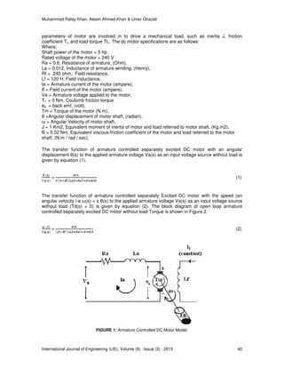
2.1 Dynamic Model of DC Motor
This part presents the dynamic model of closed loop armature controlled DC motor speed control
system. The simulation of armature controlled DC motor has been performed on Simulink/ Matlab
software. The separately excited DC motor dynamic model and its design parameters have been
taken from Carnegie Mellon, Control Laboratory of University of Michigan, US [3]. This system
model consist of a armature controlled separately excited DC motor in which speed is being
controlled by the applied armature voltage Va and the field current If is held constant. The
armature controlled DC motor model is depicted in figure 1.
The speed range of separately excited dc motor can be from zero to rated speed. This
performance is mostly achieved by the variable armature voltage applied in the constant torque
condition. The input voltage is applied to the armature terminals of the motor. The three](https://image.slidesharecdn.com/ije-485-151214124940/85/Speed-Control-of-DC-Motor-under-Varying-Load-Using-PID-Controller-2-320.jpg)
![Muhammad Rafay Khan, Aleem Ahmed Khan & Umer Ghazali
International Journal of Engineering (IJE), Volume (9) : Issue (3) : 2015 41
FIGURE 2: Simulink diagram of armature controlled DC motor without load.
FIGURE 3: Simulink model of armature controlled DC motor with load.
The transfer function block diagram of armature controlled separately Excited DC motor with the
speed (an angular velocity ω(s) to the applied armature voltage Va(s) with load (Td(s)) is also
depicted in figure 3.
2.2 Proposed System Description
In this part, the proposed model of separately excited DC motor system for speed control under
varying load is presented. The proposed control system consists of a control loops for speed and
armature current. A proportional-integral, Derivative (PID) controller is employed in this control
system in order to get desired response of speed-Torque characteristics and overcome the
problems of motor speed control under the effects of varying load.
The actual motor speed is measured by the armature current necessary for the motor. The actual
speed of the motor is sensed by the feedback control loop and compares this speed with the
preset reference speed in order to determine the required motor’s reference armature current.
The simulation of proposed system model has been accomplished in two steps. In the first one,
actual speed is setup with the reference speed with no-load condition. Next, the speed is setup
with the reference speed under varying load and the speed is kept constant.
The PID controller is very popular and common in process control industry. In the PID
(proportional-integral-derivative) closed control loop controller, the three controllers P,I and D all
have different tuning adjustments which interact all together that’s why its tuning is time
consuming and challenging task [4]. The effects of all three individual controllers (P-I-D) summed
together to produce the output value of the system [2]. Tuning of PID controller is the major task](https://image.slidesharecdn.com/ije-485-151214124940/85/Speed-Control-of-DC-Motor-under-Varying-Load-Using-PID-Controller-4-320.jpg)
![Muhammad Rafay Khan, Aleem Ahmed Khan & Umer Ghazali
International Journal of Engineering (IJE), Volume (9) : Issue (3) : 2015 42
of this device in order to proper functioning of the PID controller under the given circumstance of
the control system [7]. There are different tuning methods used to tune PID controller such as
Ziegler-Nichols method, manual tuning method and MATLAB tuning method [5]. PID controller is
the best choice for dynamic control system with no-steady state error, fast response, and superior
stability without oscillations. The P-I-D controller can be used for processes with higher order.
The variable e(s) stand for the error signal used to track the reference signal. The variable e(s) is
the difference between the desired reference input set point value r(s) and the actual output ω(s).
This error signal is sent to the PID controller and then controller evaluates the derivative and the
integral of the error signal. The output signal (u) of the controller becomes equal to the
proportional gain (Kp) times the magnitude of the error plus the integral gain (Ki) times the
integral of the error plus the derivative gain (Kd) times the derivative of the error. The signal (u)
will now be sent to the plant, and get the new generated output ω(s).This output will be again
return back to the sensor in order to determine the new error signal e(s). The new error signal will
be again sent to the controller and computes both derivative and integral again. The above
process repeats in the same manner. The signal (u) can be represented as follow [2].
(3)
In this paper, Ziegler-Nichols tuning method has been employed in the first step which overcomes
the overshoot problem of reference speed with the actual speed under no-load and eliminates the
steady state error. By using Ziegler-Nichols tuning method also known as ‘ultimate cycle method’,
determined the parameter values of each controller that is; Kp; proportional gain, Ki; integral gain
and Kd; derivative gain[2]. Ziegler Nichols tuning chart is given in Table 1. In the next step,
manual tuning is accomplished to overcome the undershoot problem of the motor speed under
the loading effect. The Block diagram of armature controlled S.E.DC motor with PID controller
under the effect of the load is illustrated in Figure 4. The output of PID controller is applied as an
input voltage to the armature terminals of the DC motor. The ultimate parameter values for the
‘PID Controller’ are KP = 2500, Ki = 3500 and Kd = 1100.
Kc TI TD
P KU/2
PI KU/2.2 PU/1.2
PID KU/1.7 PU/2 PU/8
TABLE 1: ZIEGLER-NICHOLS Tuning Chart.
FIGURE 4: Block diagram of armature controlled SEDC motor with PID controller under the effect of load.](https://image.slidesharecdn.com/ije-485-151214124940/85/Speed-Control-of-DC-Motor-under-Varying-Load-Using-PID-Controller-5-320.jpg)
![Muhammad Rafay Khan, Aleem Ahmed Khan & Umer Ghazali
International Journal of Engineering (IJE), Volume (9) : Issue (3) : 2015 43
2.3 The Proposed System Comparative to Previous Control System
There has been lot of research work done and published [11-14] on the same topic but the
approach of speed control technique presented in this paper is quite unique from all other
techniques already presented and published since those are mostly employed with the variation
of the control schemes. However, apart from the control schemes such as PI, PID, Fuzzy and
Sliding Mode Control etc, an idea is presented in this paper for the speed regulation of DC Motor
under varying load condition with the speed kept constant. This idea is experimentally tested on
the simulation software. By using this experiment setup, it will be justified whether the speed
regulation of the DC motor under varying load can be controlled effectively if the speed kept
constant and PID control scheme is employed to achieve this task.
3. RESULTS AND DISCUSSION
This section presents the results of the proposed speed control system model’s simulations,
which have been performed on the Simulink platform of Matlab software. The complete step by
step simulation results of DC motor speed control under the effect of load with speed – Torque
characteristic curve have been illustrated in this section.
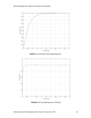
The block diagram of system model without and with PID controller is developed on the Simulink
platform. First of all, the step response of the system model without PID controller is taken and
illustrated in figure 5. The output voltage reached up to the 0.1v (10% of the final value) when the
1V unit step volt is applied at the input. The rise time is 1.2 seconds, while the settling time is 1.5
seconds. The steady state error is about 90% of the final value.
In the next step of this experiment, the PID controller has been employed in the existing block
diagram of system model in order to attain the desired speed. The step response of PID
controlled system model is shown in figure 6. The output voltage reaches up to the desired value
of 1V. The rise time has been greatly reduced and is only 0.2 second, while the settling time for
PID controlled system is 0.25 second.
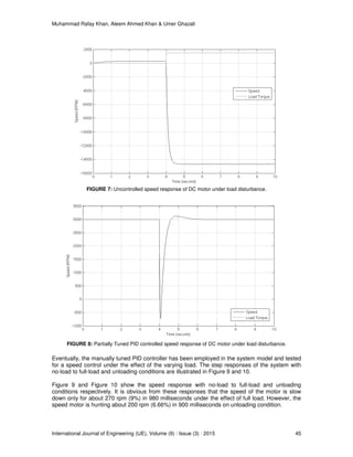
After that, the system model has been tested without PID controller with full load condition. The
speed – torque step response is also shown in figure 7. It is obvious that the speed is not attained
to the desired reference value. It has also been observed from the graph that the speed slows
down for about 15000 rpm below the running speed as the load torque changes from 0 to 1500.
Next, once again the PID controller is employed in the existing block diagram of system with load
disturbance. PID controller is used to overcome the current problem of speed control under the
effect of load. The simulation graph of the system model is demonstrated in the figure 8. By using
the same parameter values of PID controller, the response of the system become good with
respect to the desired speed sustainability with zero load torque. However, this speed
sustainability become drastically demolishes as the load torque changes from zero to 1500Nm.
This figure illustrates that the motor speed is tremendously hunted with open loop speed control
in full-load condition.](https://image.slidesharecdn.com/ije-485-151214124940/85/Speed-Control-of-DC-Motor-under-Varying-Load-Using-PID-Controller-6-320.jpg)
![Muhammad Rafay Khan, Aleem Ahmed Khan & Umer Ghazali
International Journal of Engineering (IJE), Volume (9) : Issue (3) : 2015 47
PID controller has better control approach in order to control and sustain the speed of the motor
under varying load condition. The results also confirmed the validation of the PID based closed
loop speed control system under the effects of load disturbance.
5. FUTURE SCOPE
The targeted result is achieved successfully under the given suitable conditions. However, some
improvements can be made in the control aspects of the proposed system design. In this
experiment, the PID controller is well performed for the motor speed control under the loaded
condition while the speed is kept constant. The ultimate parameter values of PID controller were
setup by Manual Tuning method. An Adaptive approach of PID controller may be used in the
prospective development in order of effectively speed control of the motor with reference to input
speed under the effect of load.
6. REFERENCES
[1] P.C. Sen, “Principles of Electrical Machines & Power Electronics”, USA: John Wiley & Sons,
1996.
[2] K. J. Astrom and T. Hagglund,”PID controllers Theory, Design and Tuning”, 2nd edition,
Instrument Society of America, 1994
[3] “PID Design Method for the DC Motor Speed Control”, Internet:
www.dii.unisi.it/~control/ctm/examples/motor/PID2.html, 2012 [Feb 20, 2015].
[4] “WATLOW PID practical guide for process control”, Internet:
https://www.watlow.com/downloads/en/whitepapers/pid%20practical%20guide.pdf, Aug
2005, [Feb 17, 2015].
[5] M. Shahrokhi and A. Zomorrodi , “Comparison of PID Controller Tuning Methods”, Internet:
www.personal.psu.edu/users/a/u/auz107/Publications-files/Zomorrodi-Shahrokhi-PID-
Tunning-Co mparison.pdf, 2013 [Jan 25, 2015].
[6] W. Djatmiko and B. Sutopo, “Speed Control DC Motor under Varying Load Using Phase-
Locked Loop System”, International Conference on Electrical, Electronics, Communication
and Information CECI, Jakarta 2001
[7] Elsrogy, Fkirin, Hassan, “Speed control of DC motor using PID controller based on artificial
intelligence techniques” International Conference on Control, Decision and Information
Technologies (CoDIT), 2013, pp. 196-201
[8] Rajeshkanna, “Modern speed control of separately excited DC Motor by Boost converter fed
field control method”, International Conference on Computer Communication and
Informatics (ICCCI), 2013, pp. 1-7
[9] K. Rajanwal, R. Shakya, S. Patel, R. K. Maurya, “Comparative Analysis of PI, PID and
Fuzzy Logic Controllers for Speed Control of DC Motor”, International Journal of Engineering
Research and Technology, Vol. 3 - Issue 1, pp. 1319-1324, Jan 20, 2014.
[10] H. L. Chan and K. T. Woo, “Closed Loop Speed Control of Miniature Brushless DC Motors”,
Journal of Automation and Control Engineering, Vol. 3, No. 4, pp. 329-335, Aug 2015.
[11] C. Perez and M. Strefezza, "Speed control of a DC motor by using fuzzy variable structure
controller," in Control Conference, 2008. CCC 2008. 27th Chinese, 2008, pp. 311-315
[12] R. K. Munje, M. R. Roda, B. E. Kushare, "Speed Control of DC Motor Using PI and SMC",
Proc. of IEEE Int. Conf. on Power and Energy, Singapore, Oct 2010, pp. 945-950](https://image.slidesharecdn.com/ije-485-151214124940/85/Speed-Control-of-DC-Motor-under-Varying-Load-Using-PID-Controller-10-320.jpg)
![Muhammad Rafay Khan, Aleem Ahmed Khan & Umer Ghazali
International Journal of Engineering (IJE), Volume (9) : Issue (3) : 2015 48
[13] Aydemir,S;Sezen,S,Ertunc,H.M, "Fuzzy logic speed control of a DC Motor", Proceedings of
Int. Conf. on Power Electronics and Motor Control, vol. 2, pp. 190-194,2004
[14] A. A. El-Samahy, "Speed control of DC motor using adaptive variable structure control",
IEEE 31st Annual Power Electronics Specialists Conference, 1118-1123, 2000.](https://image.slidesharecdn.com/ije-485-151214124940/85/Speed-Control-of-DC-Motor-under-Varying-Load-Using-PID-Controller-11-320.jpg)