Downloaded 233 times
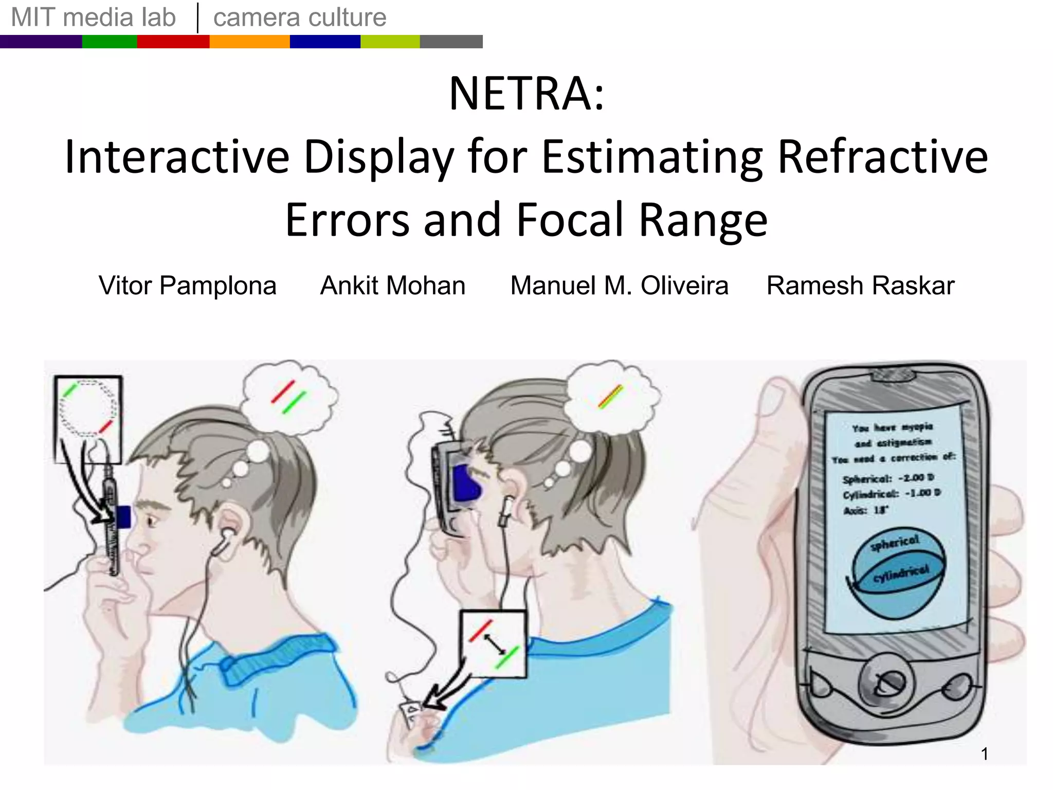
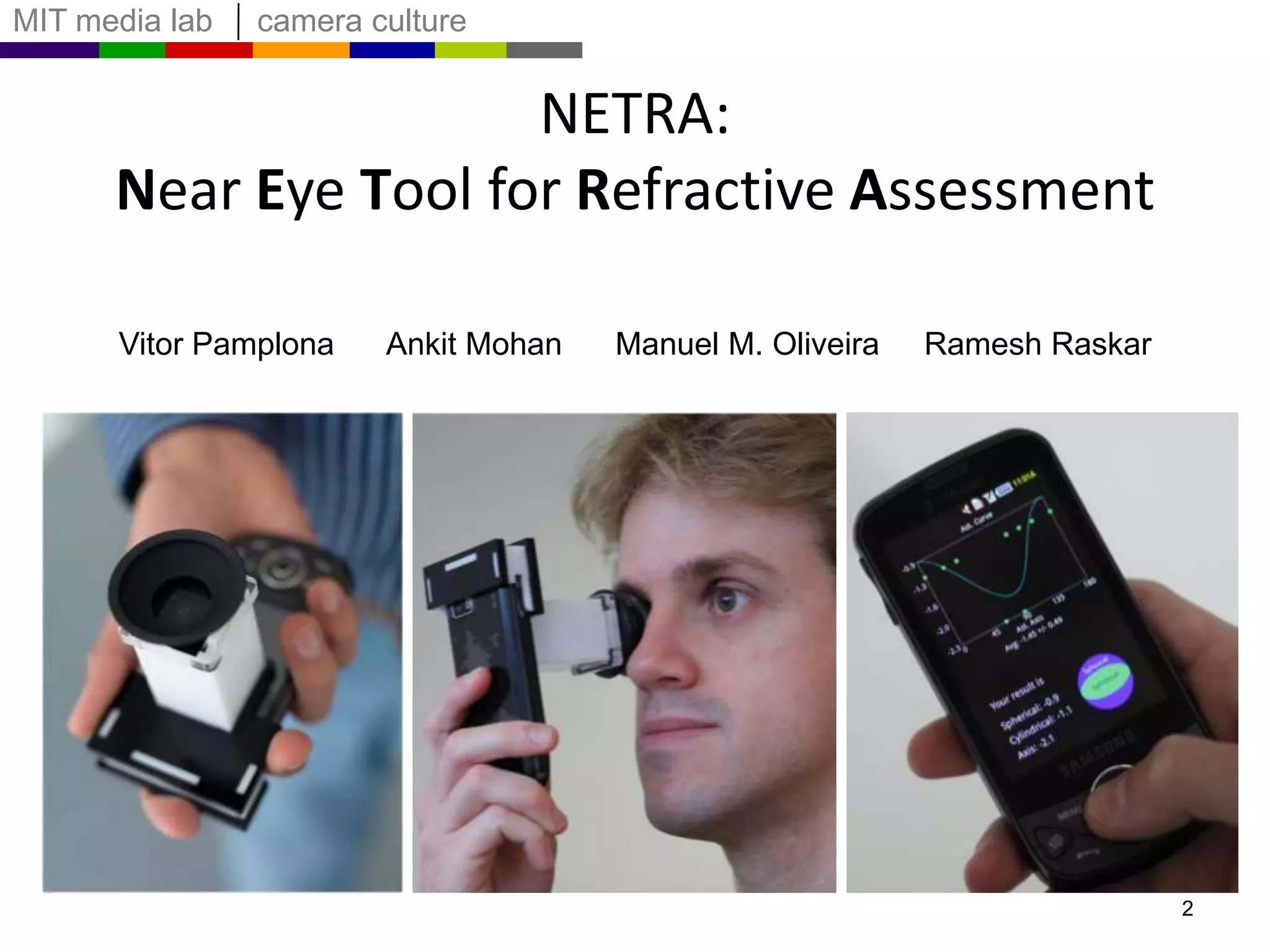
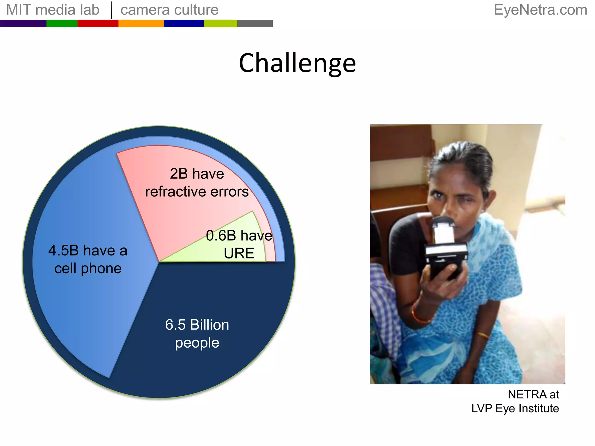
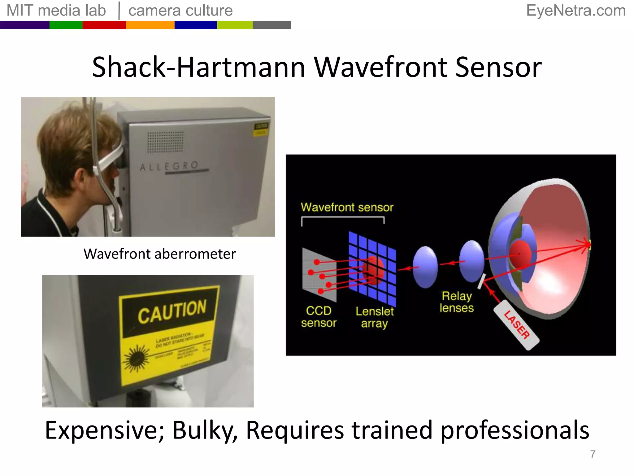
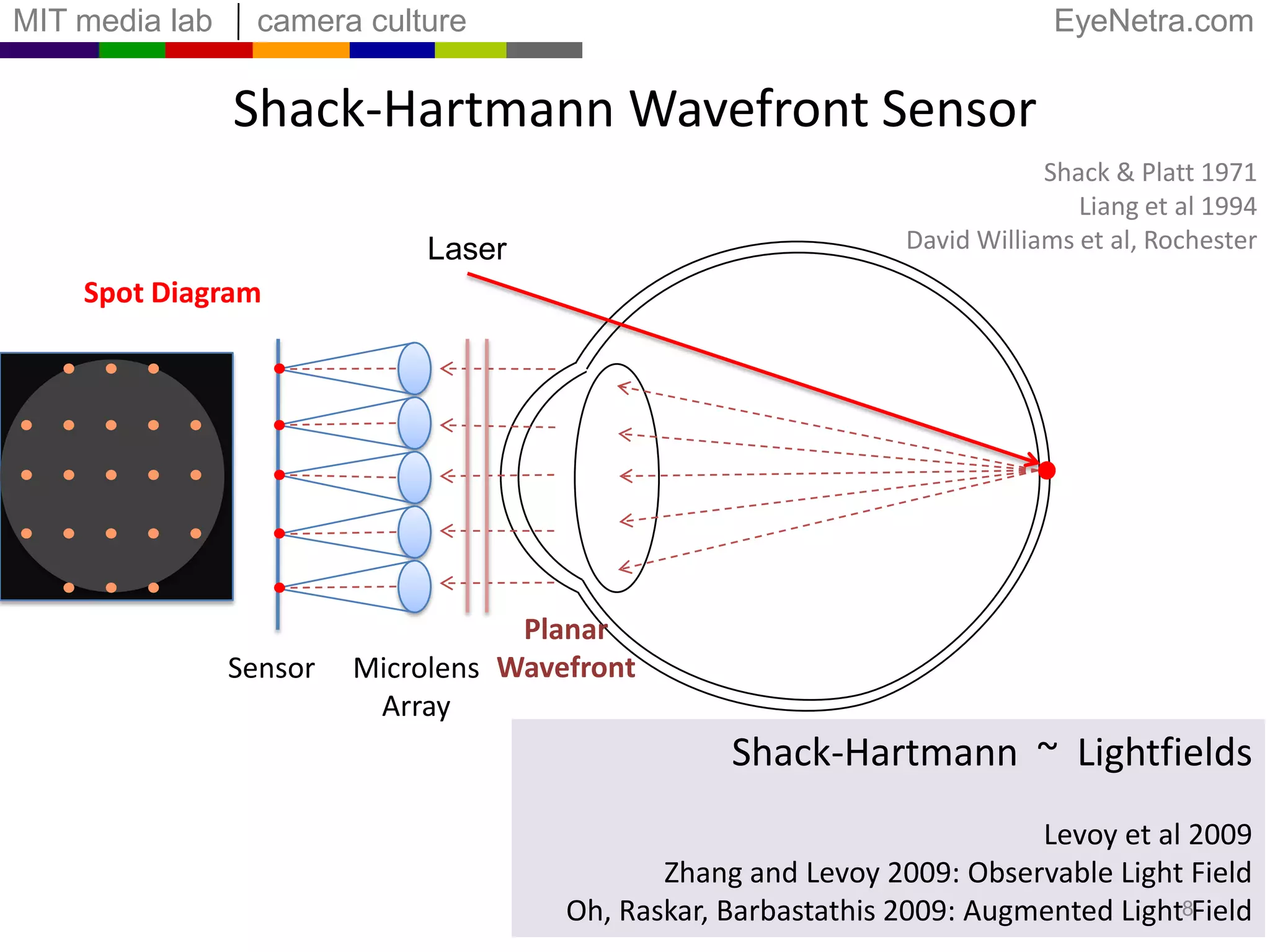
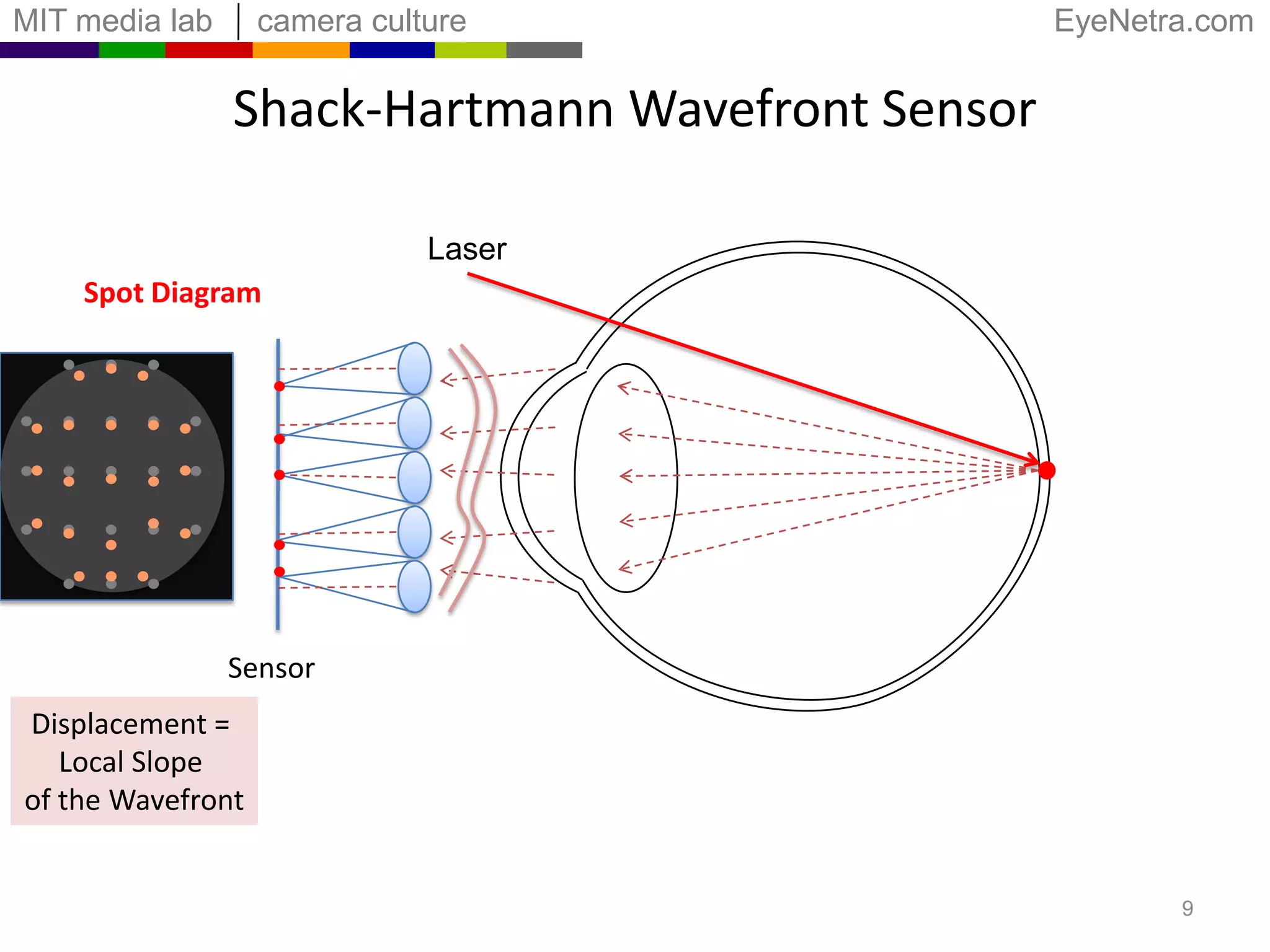
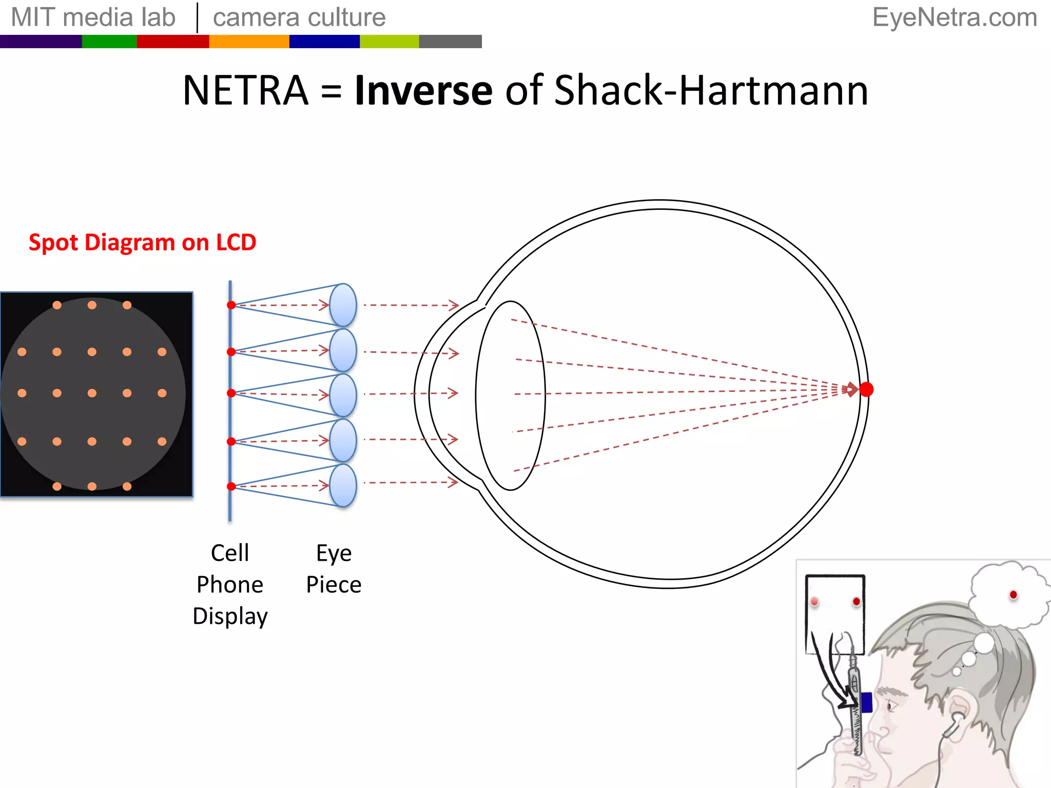
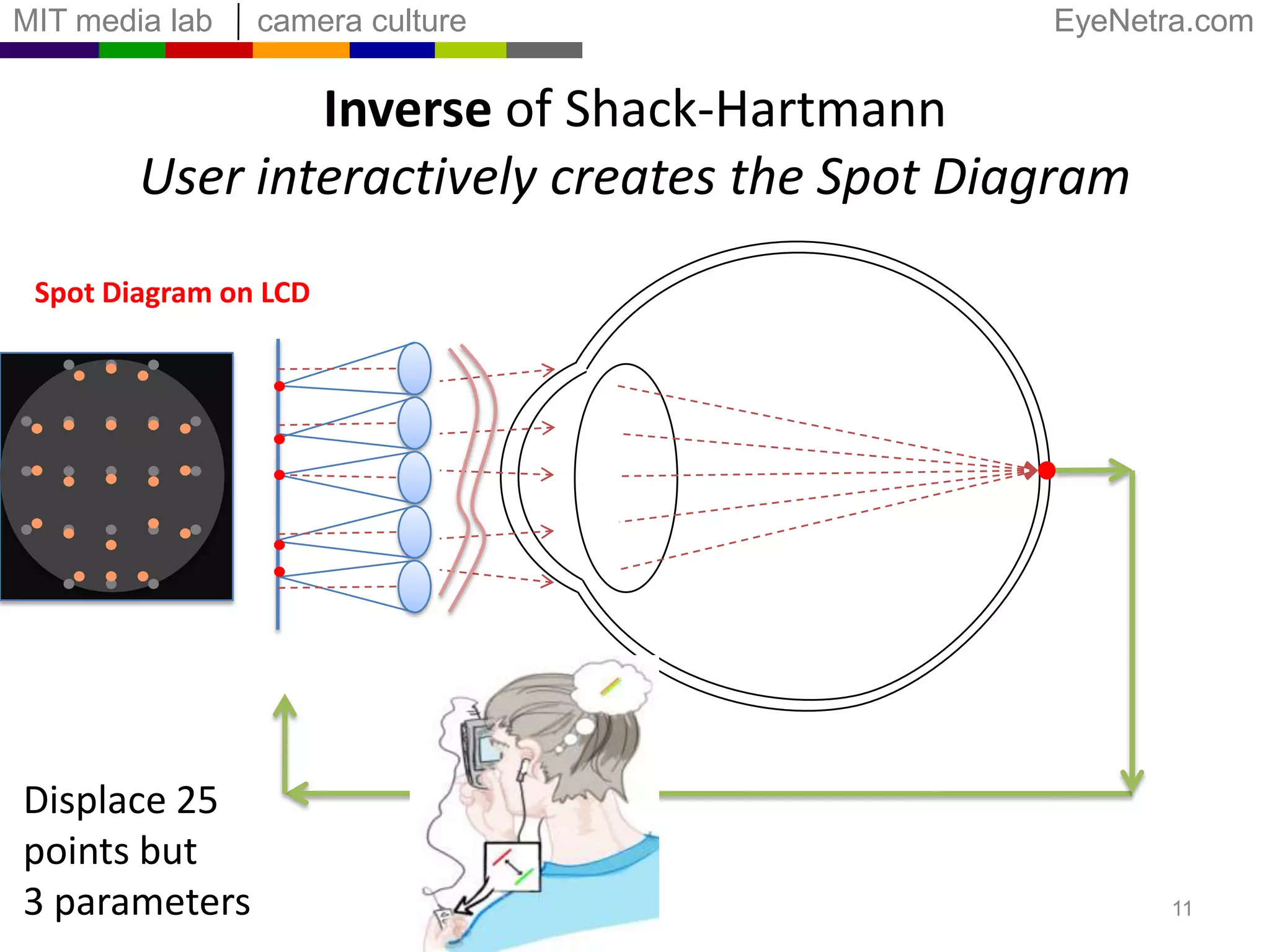
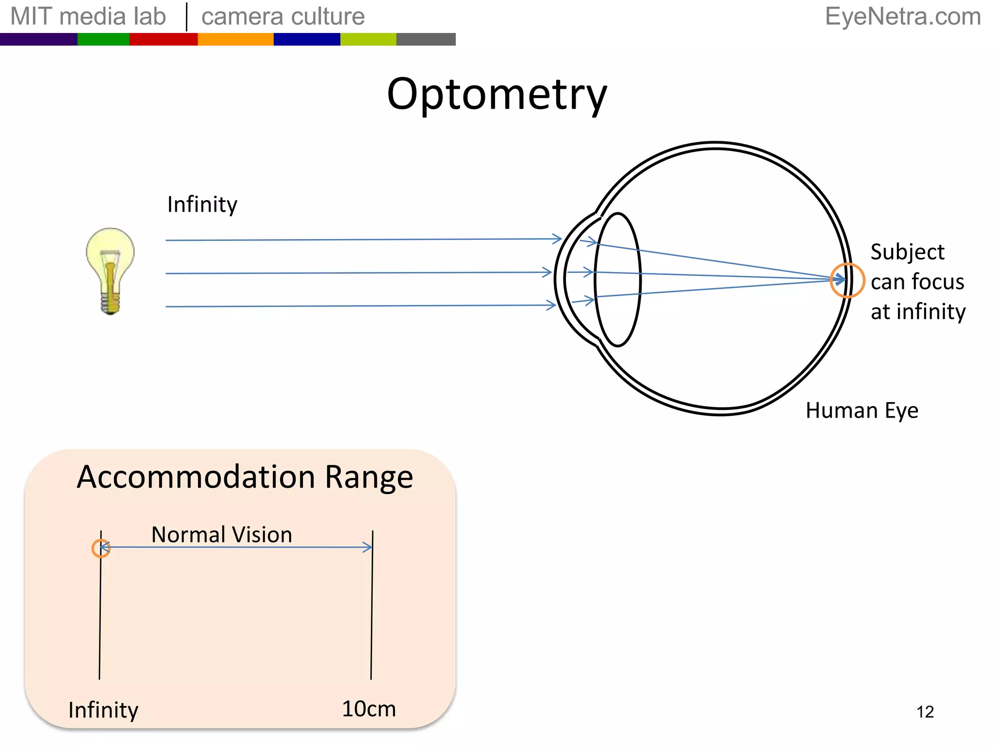
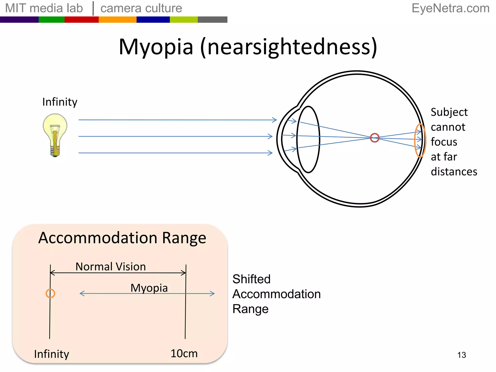
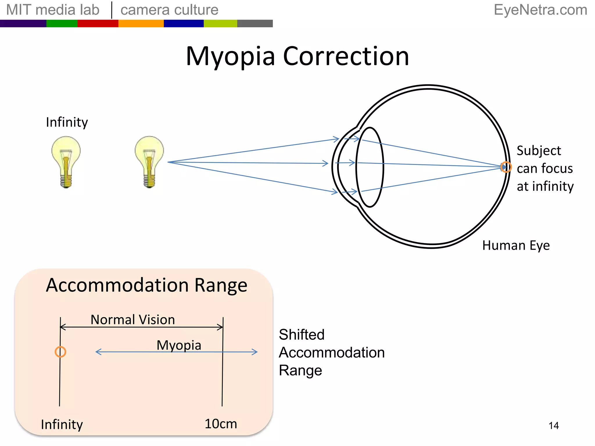
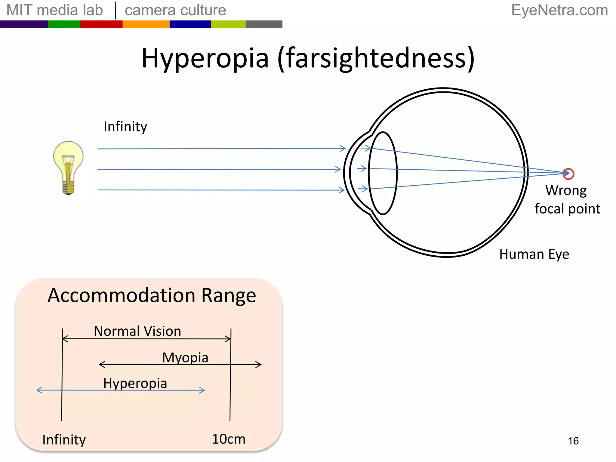
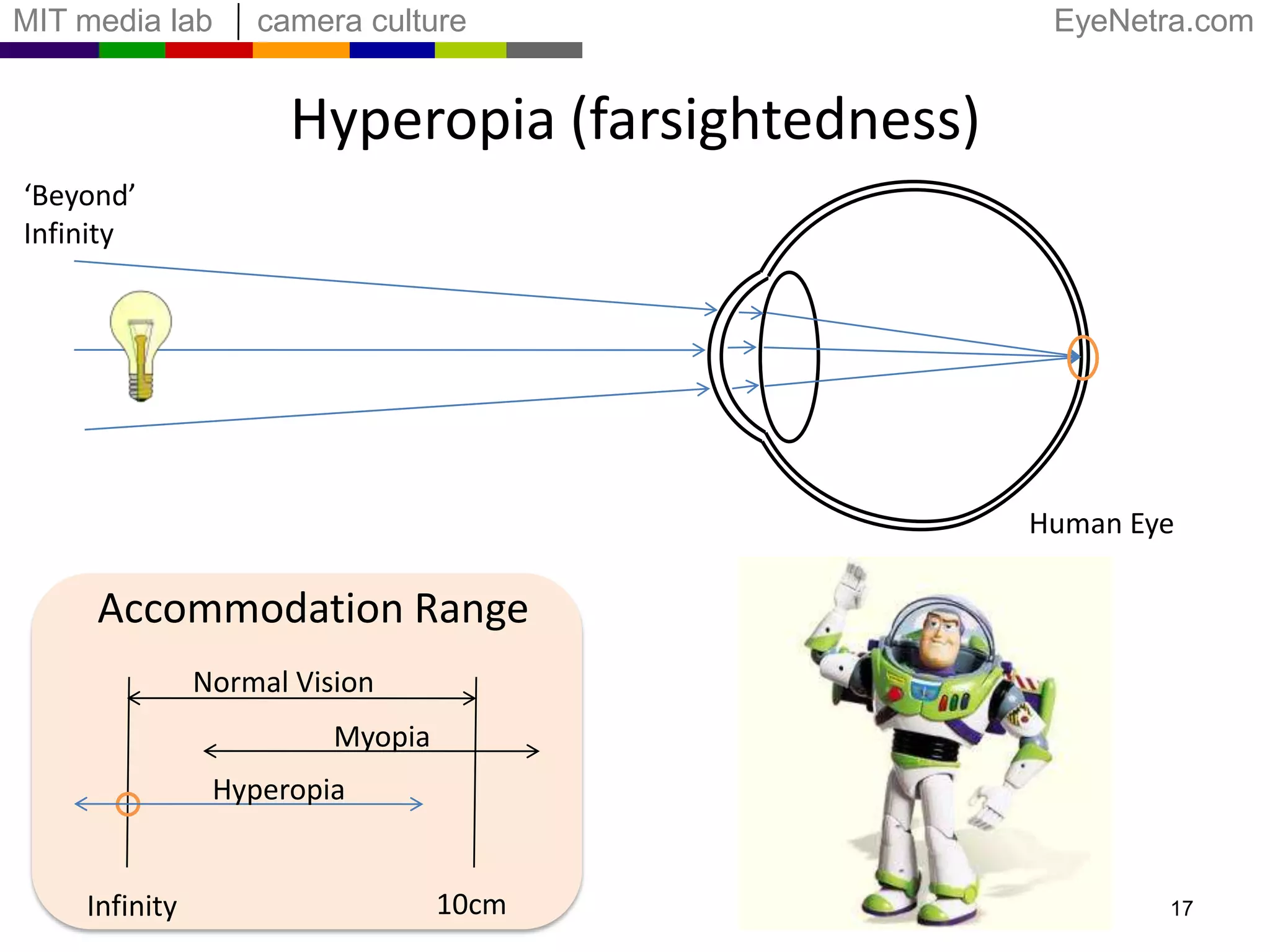
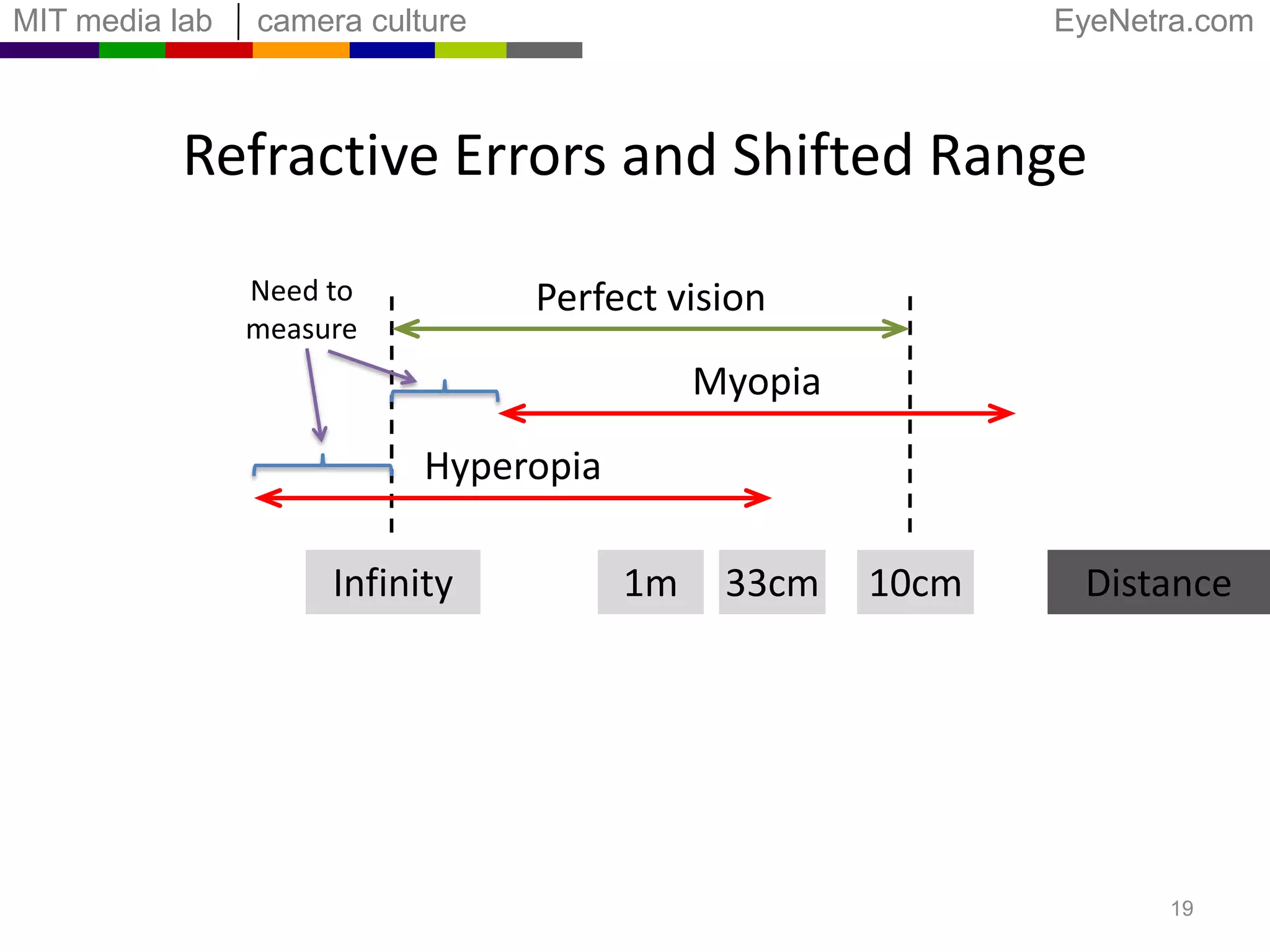
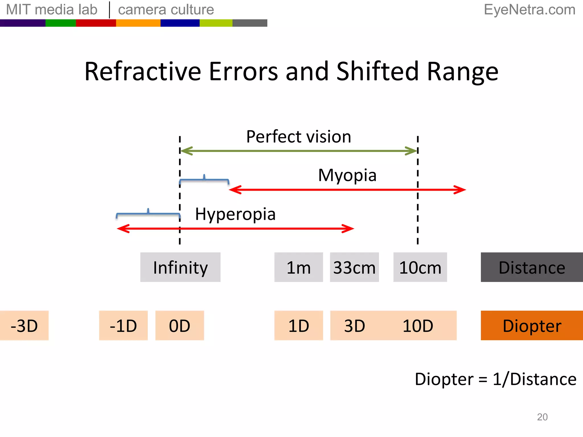
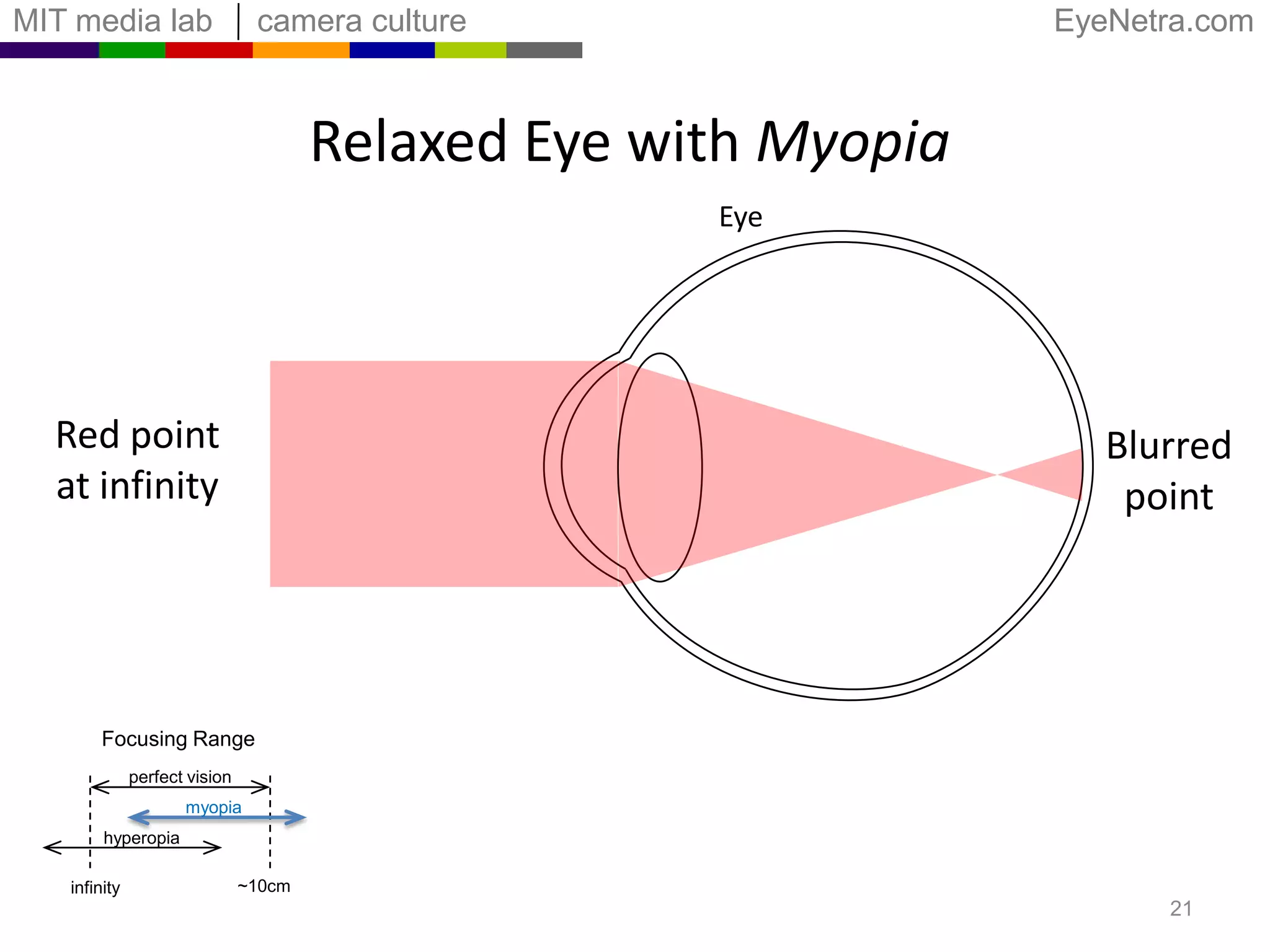
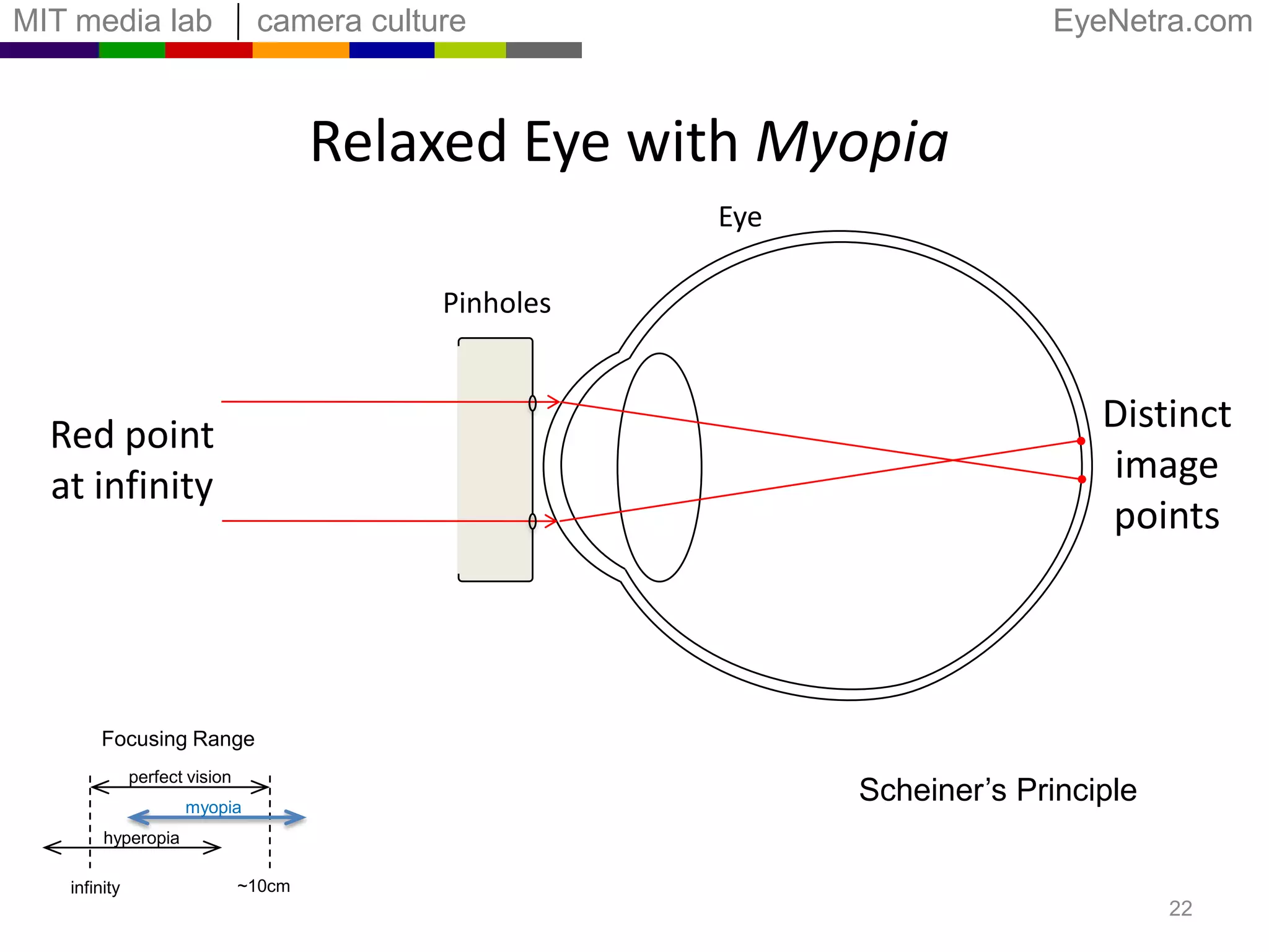
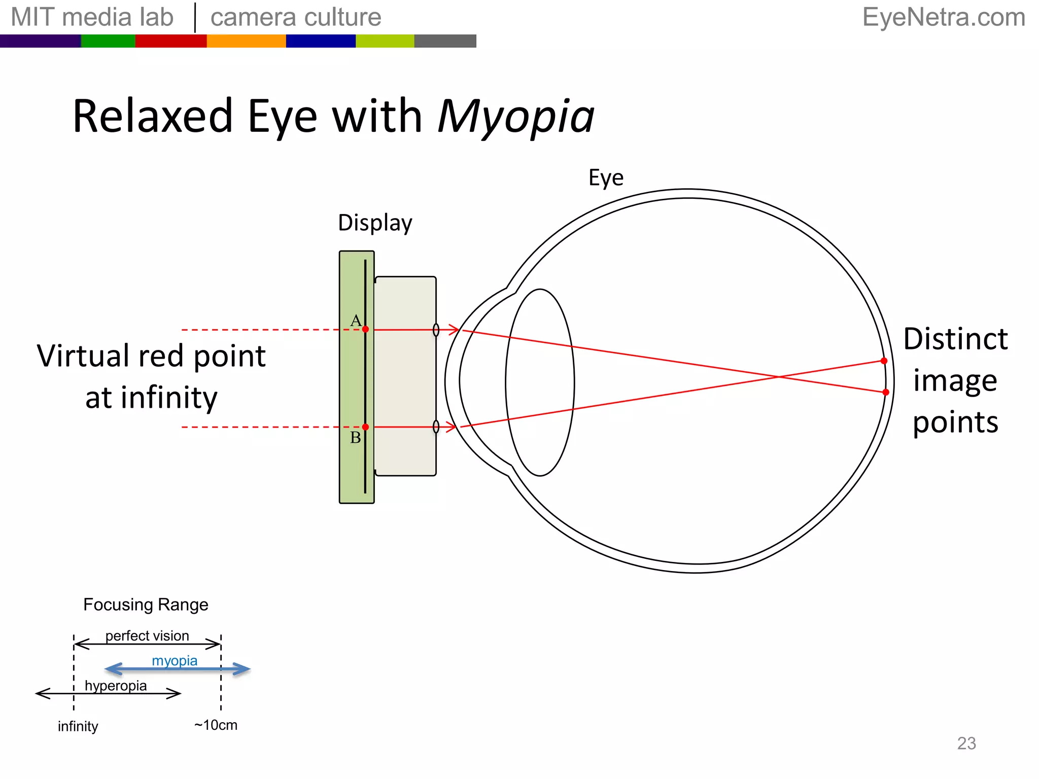
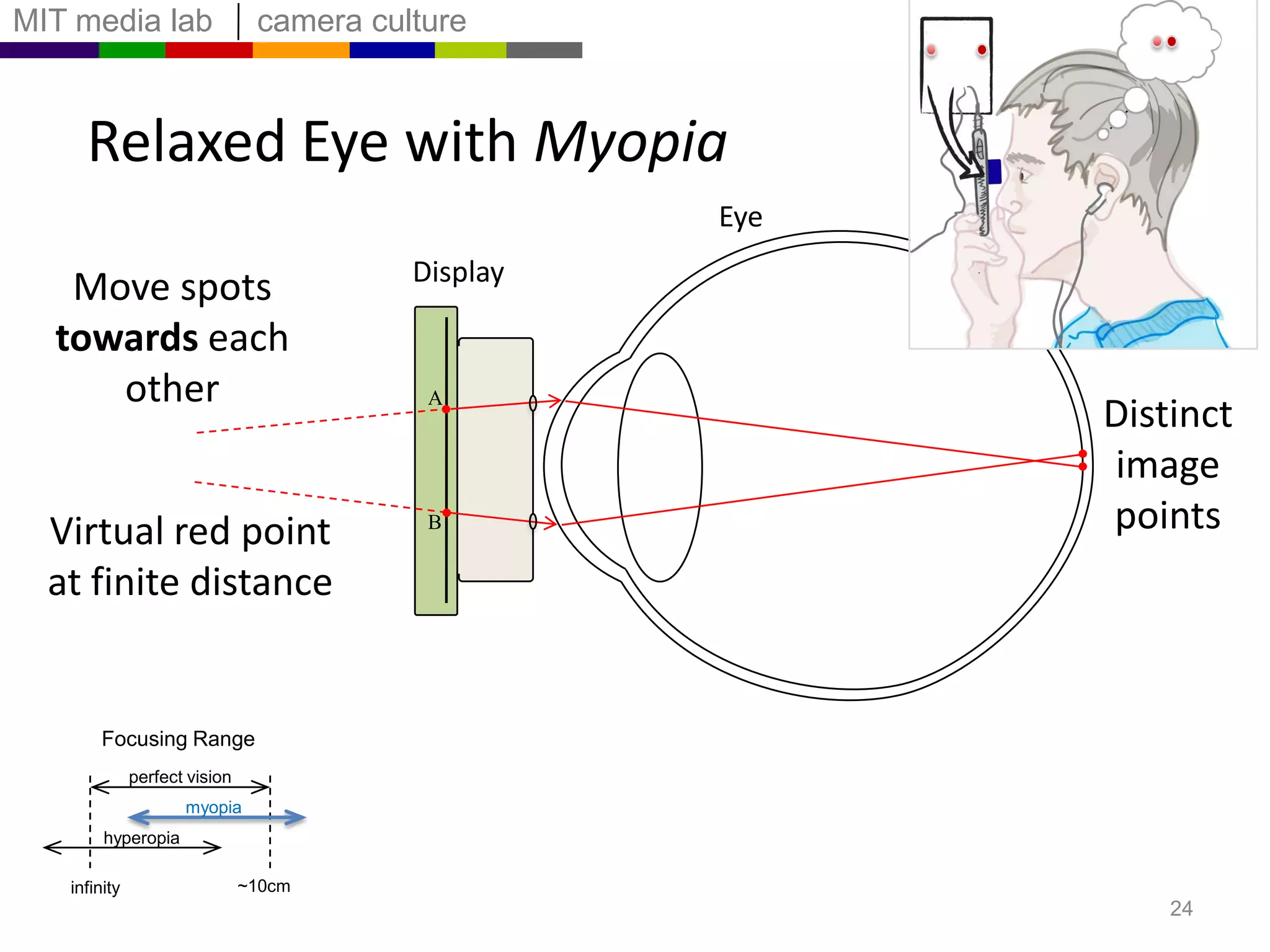
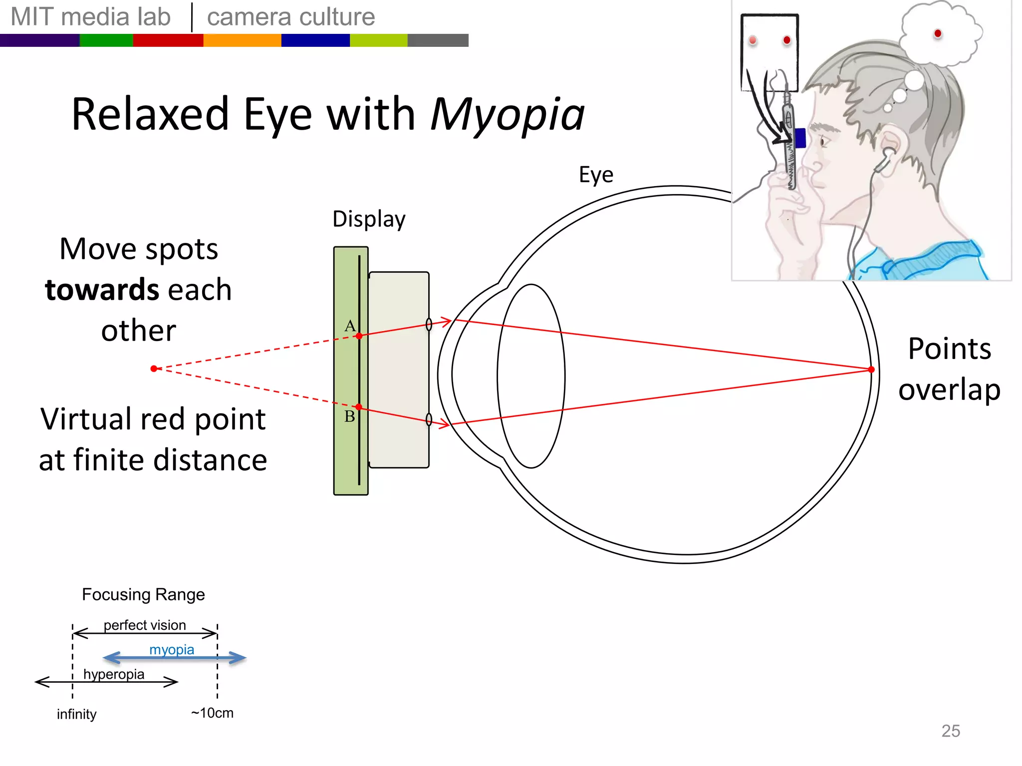
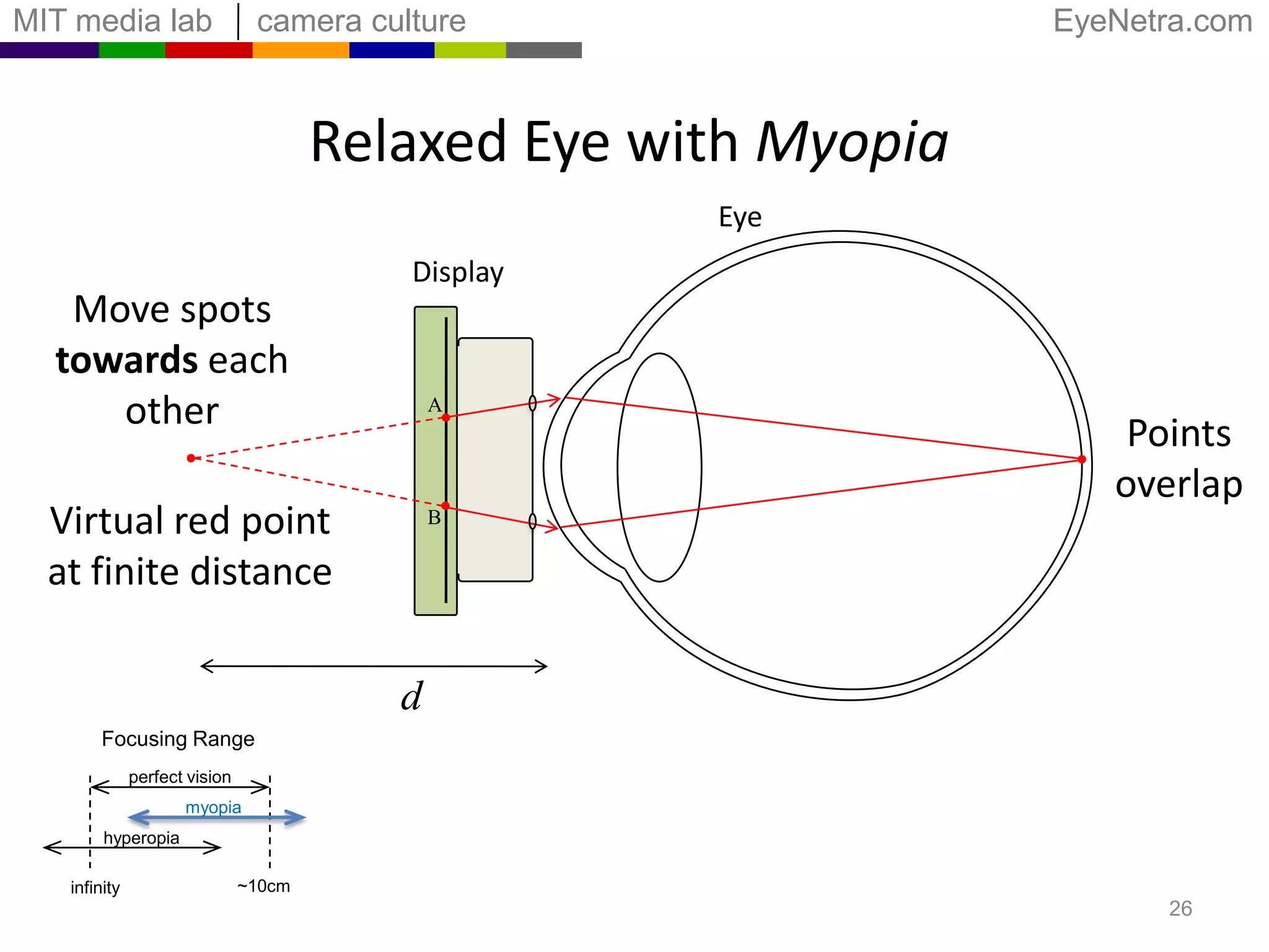
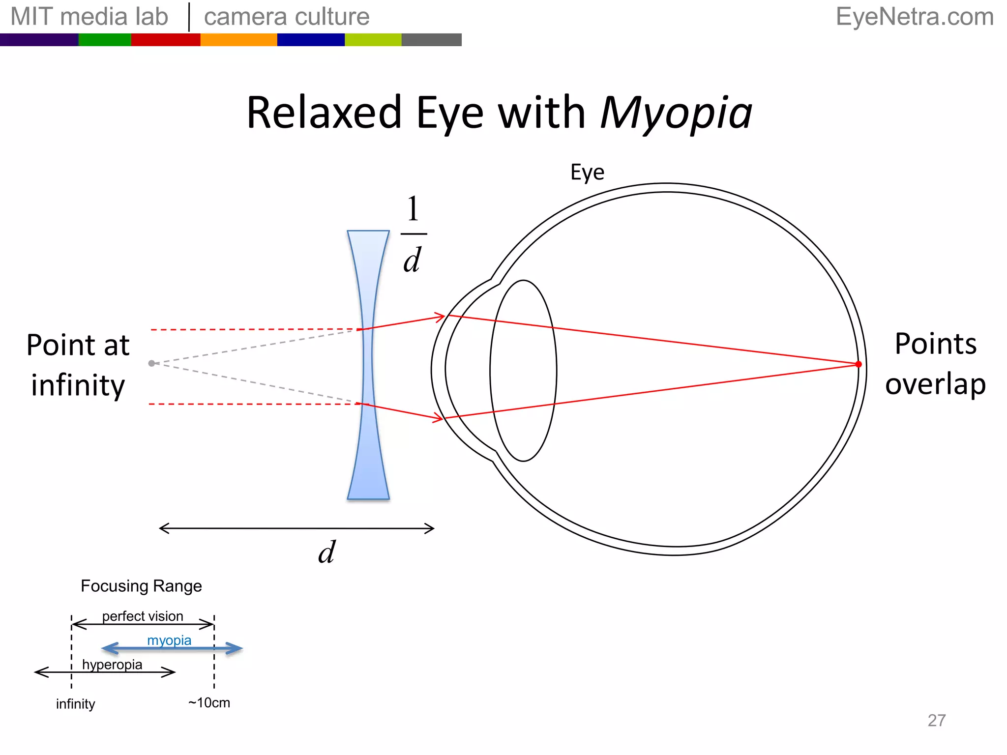
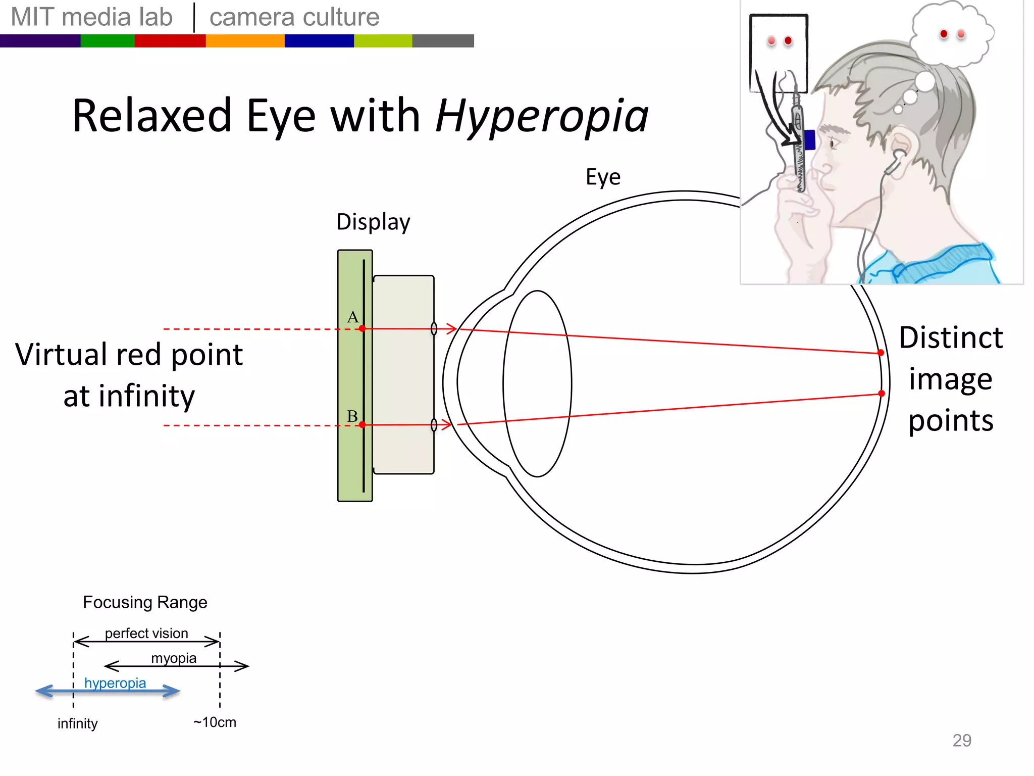
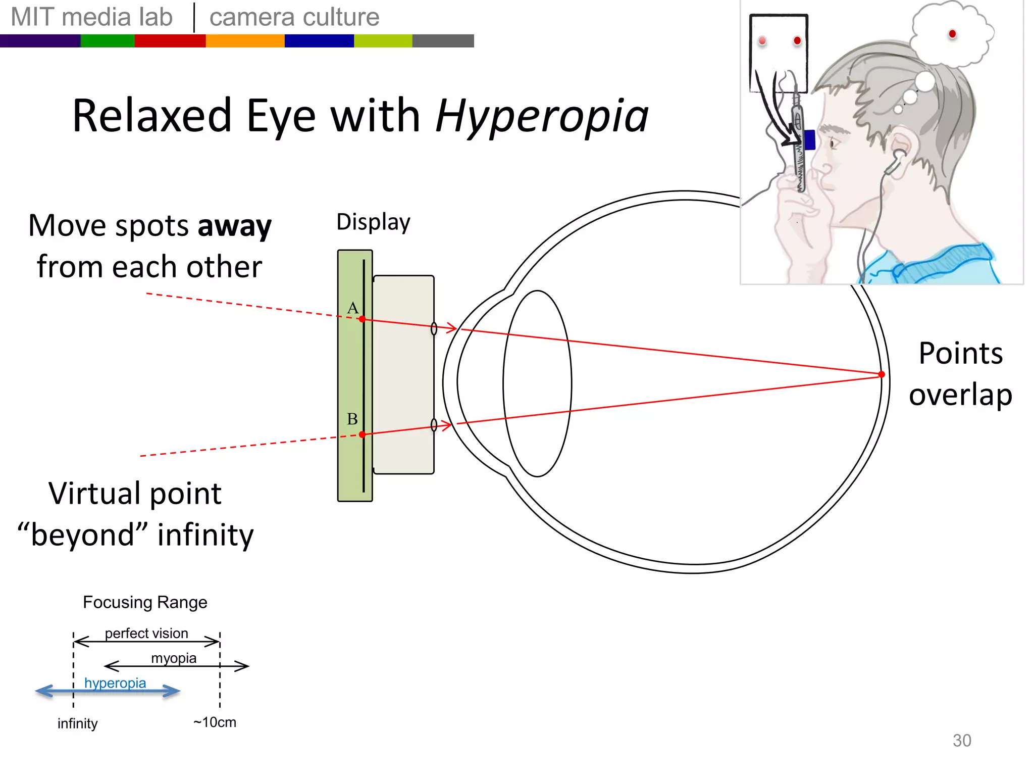
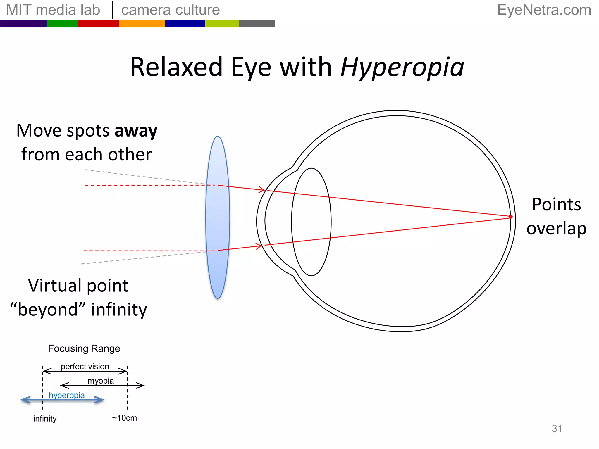
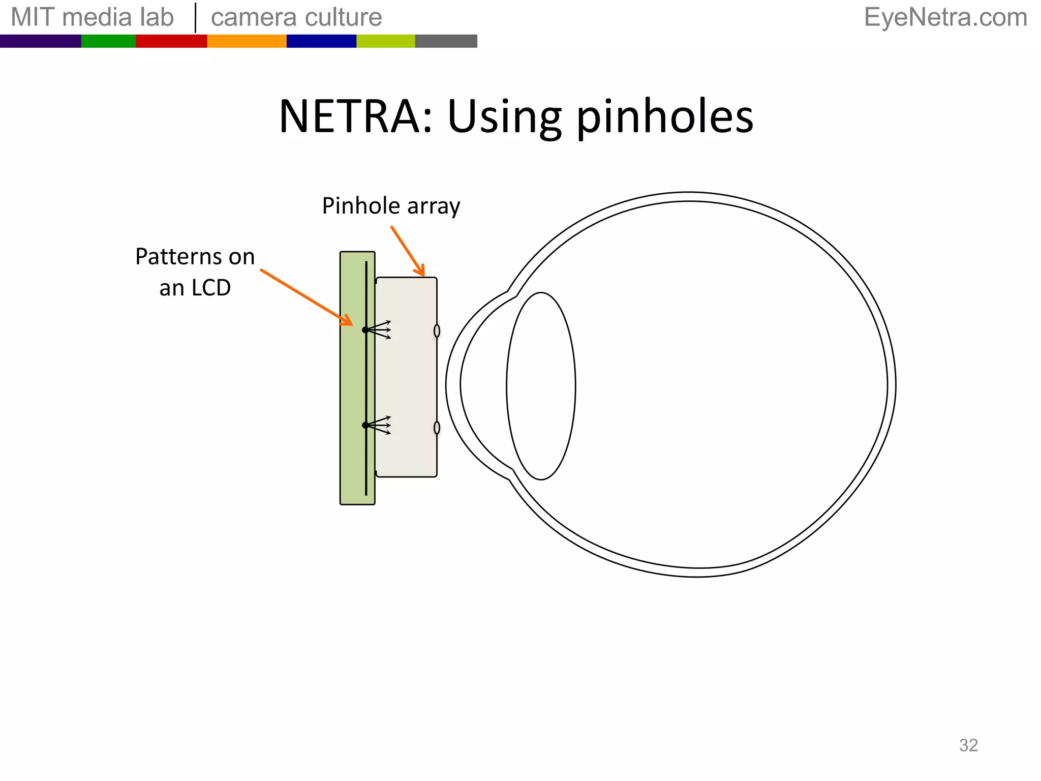
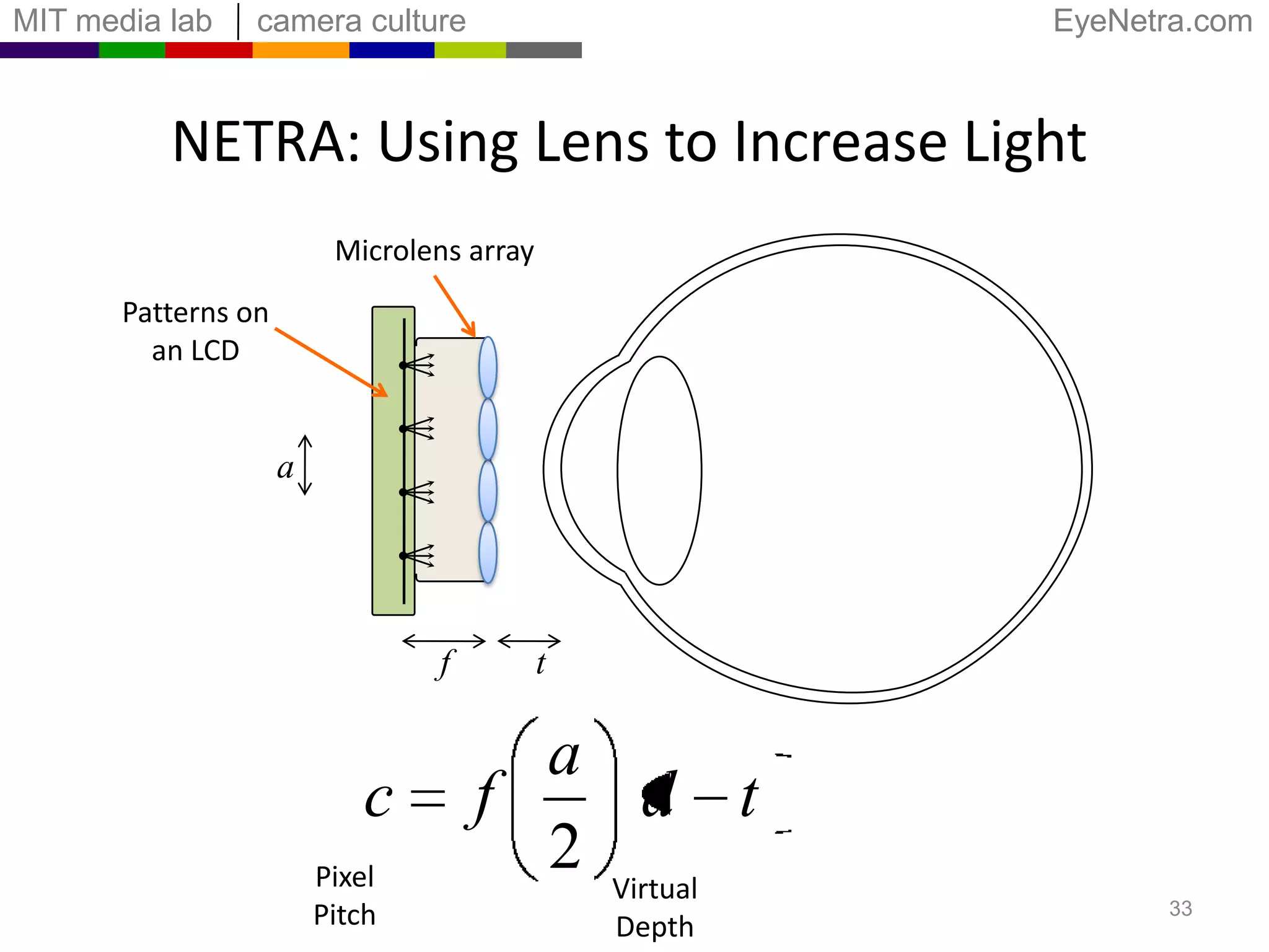
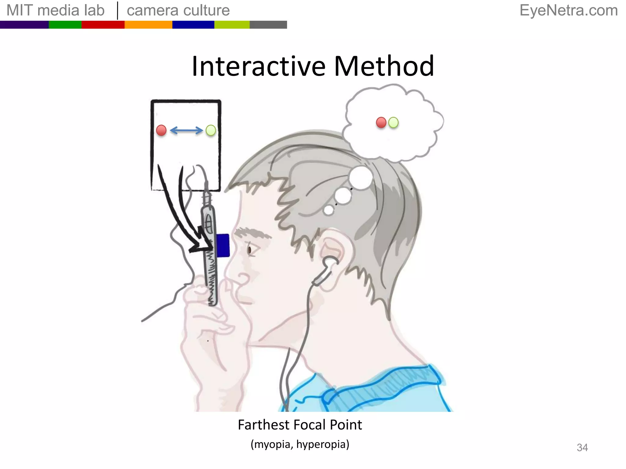


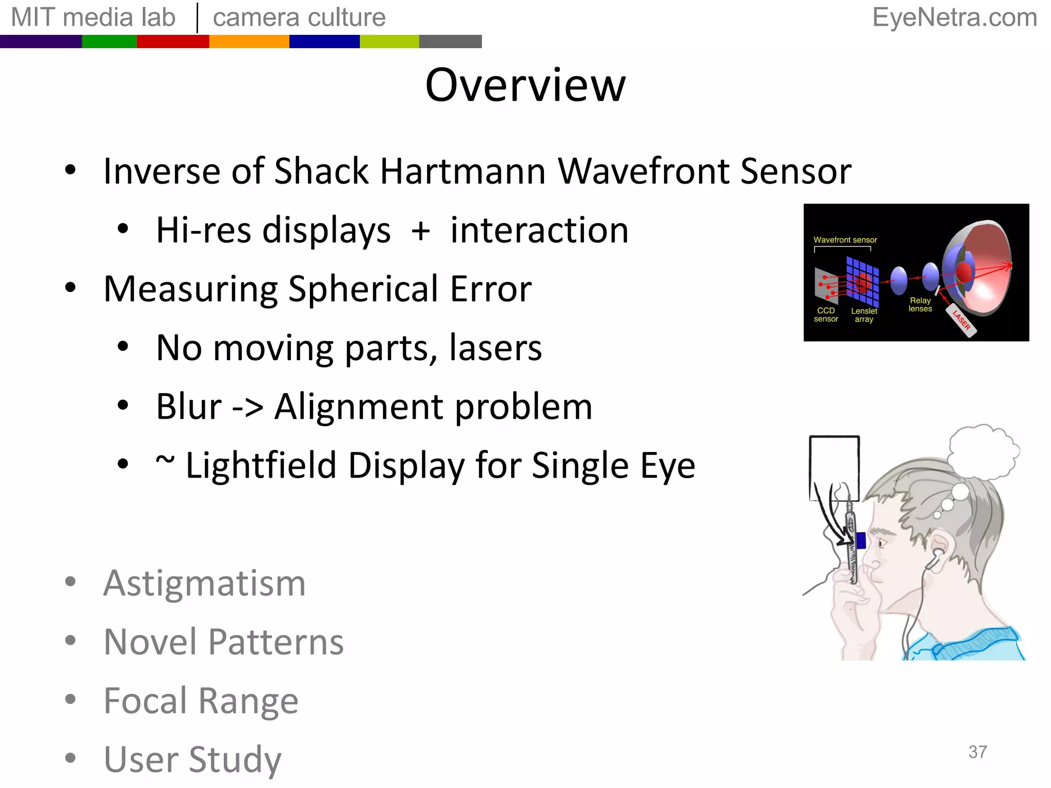
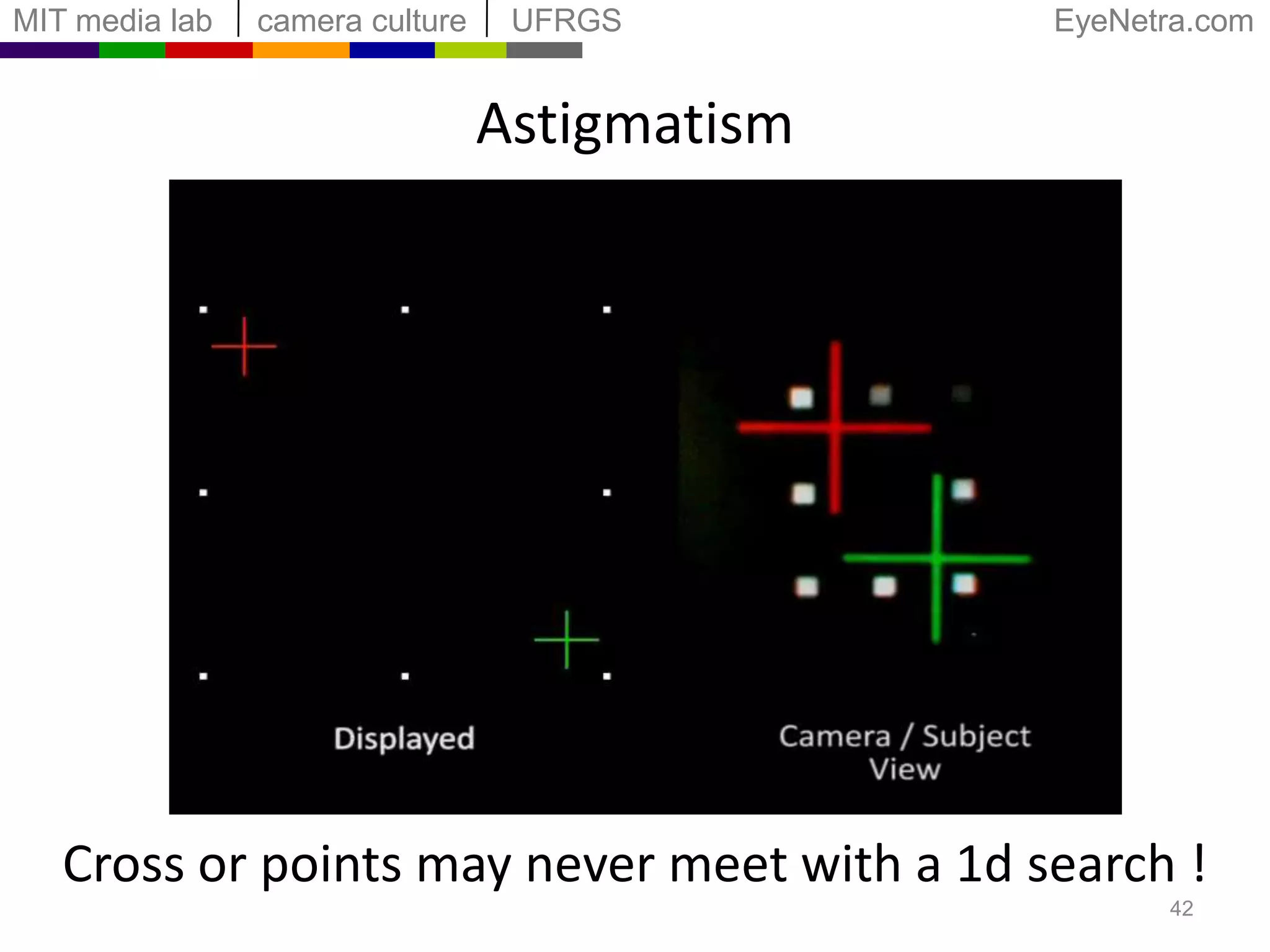
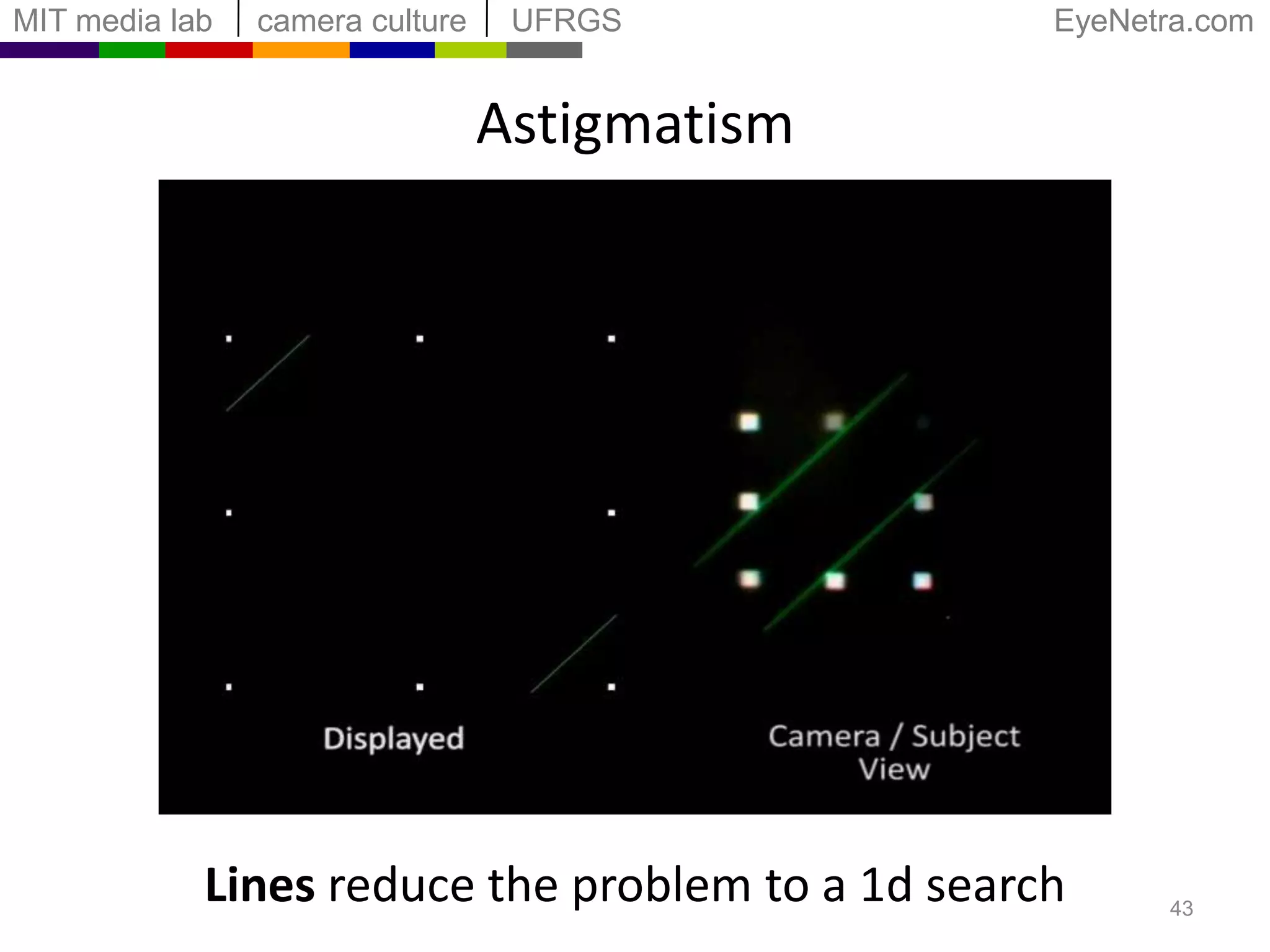

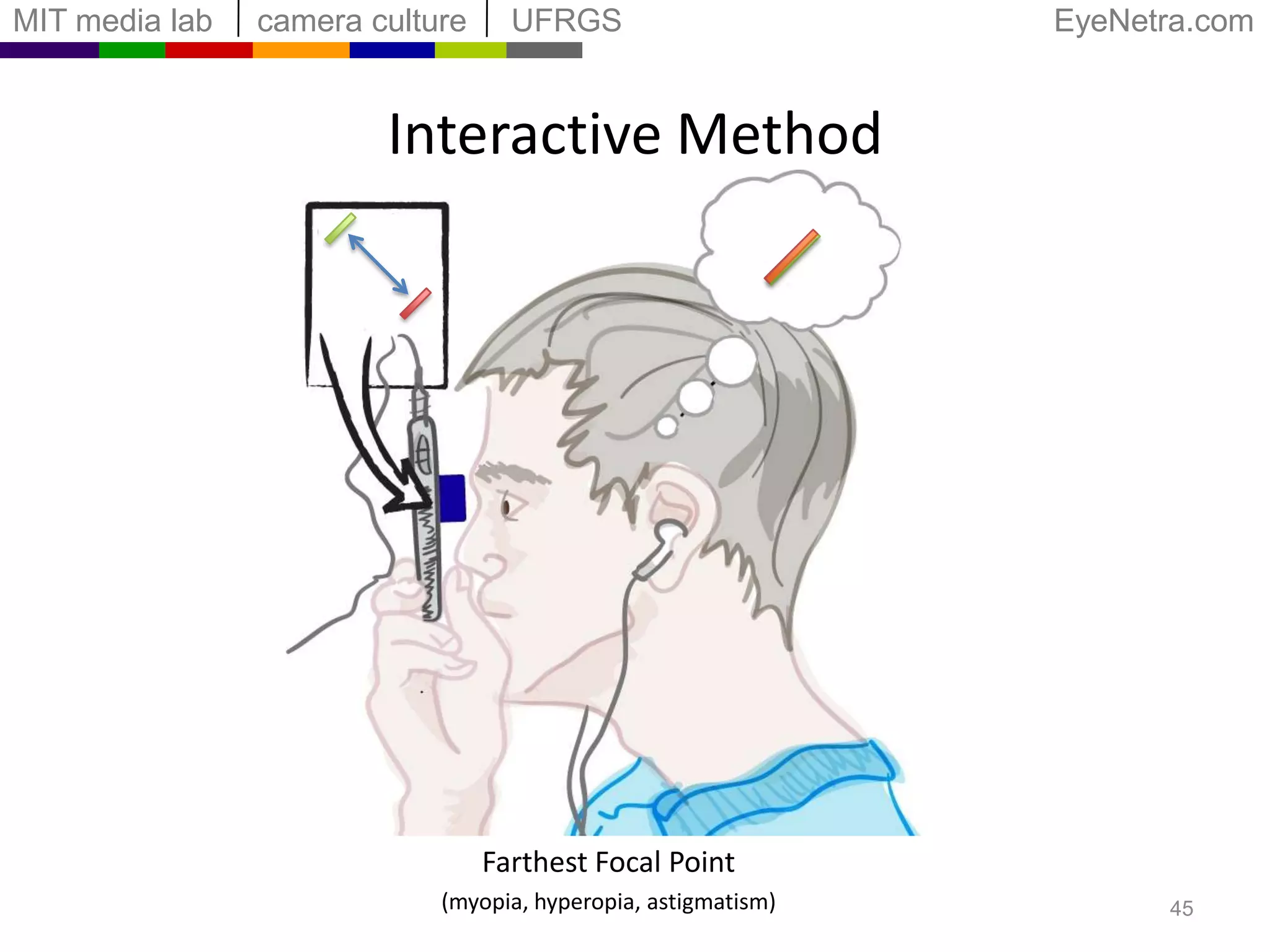


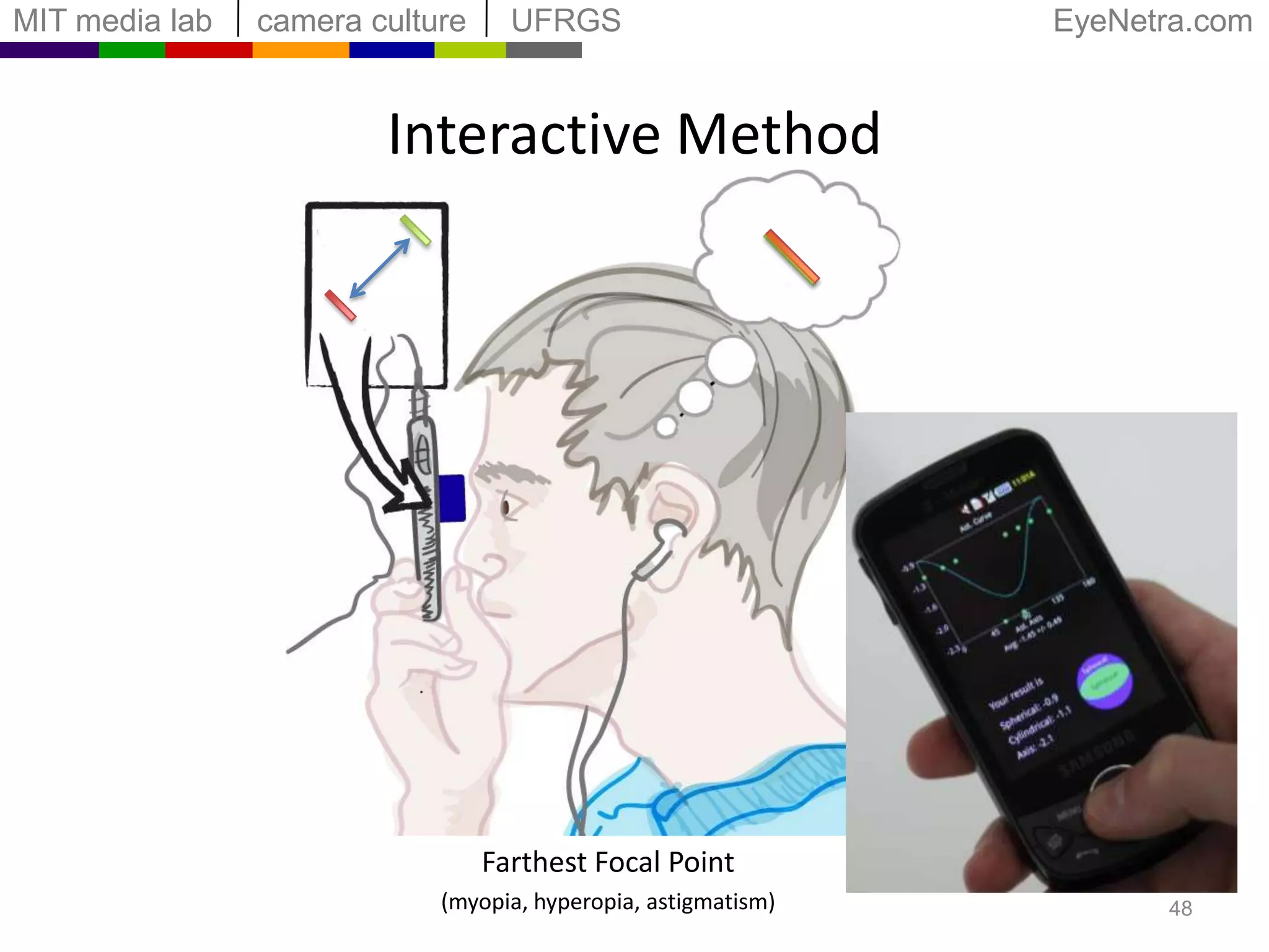

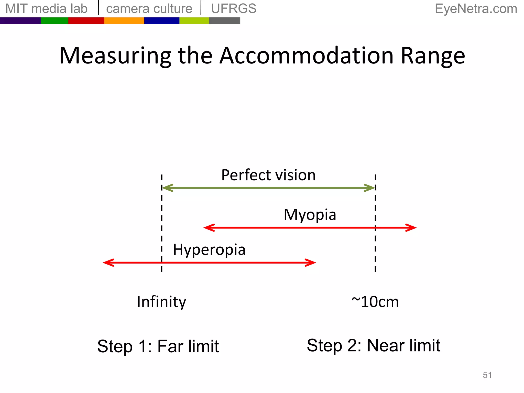
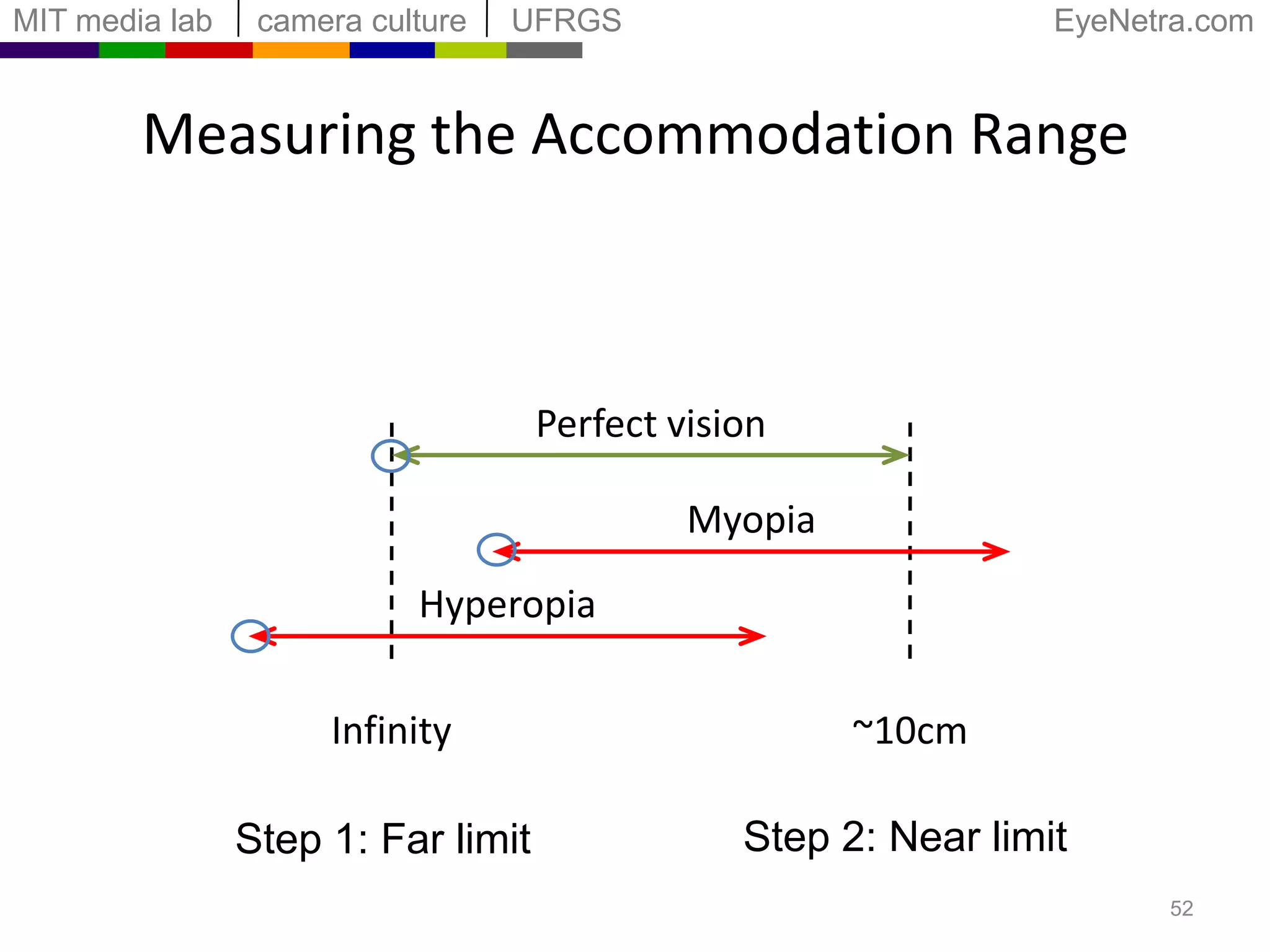
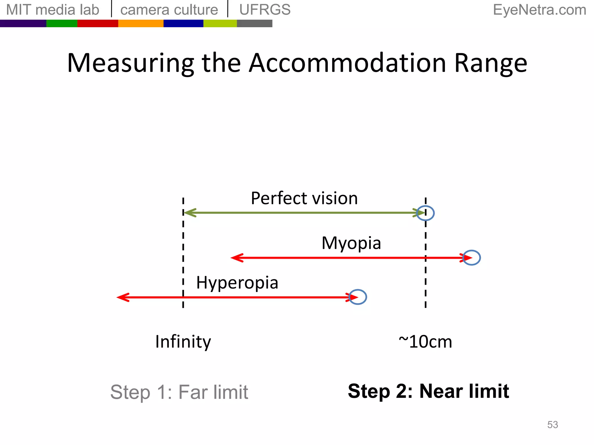
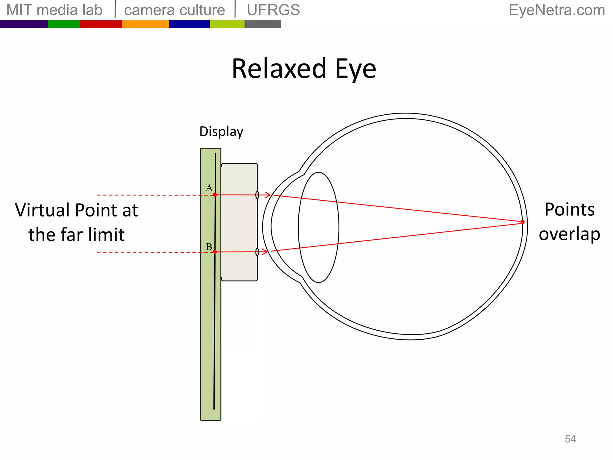
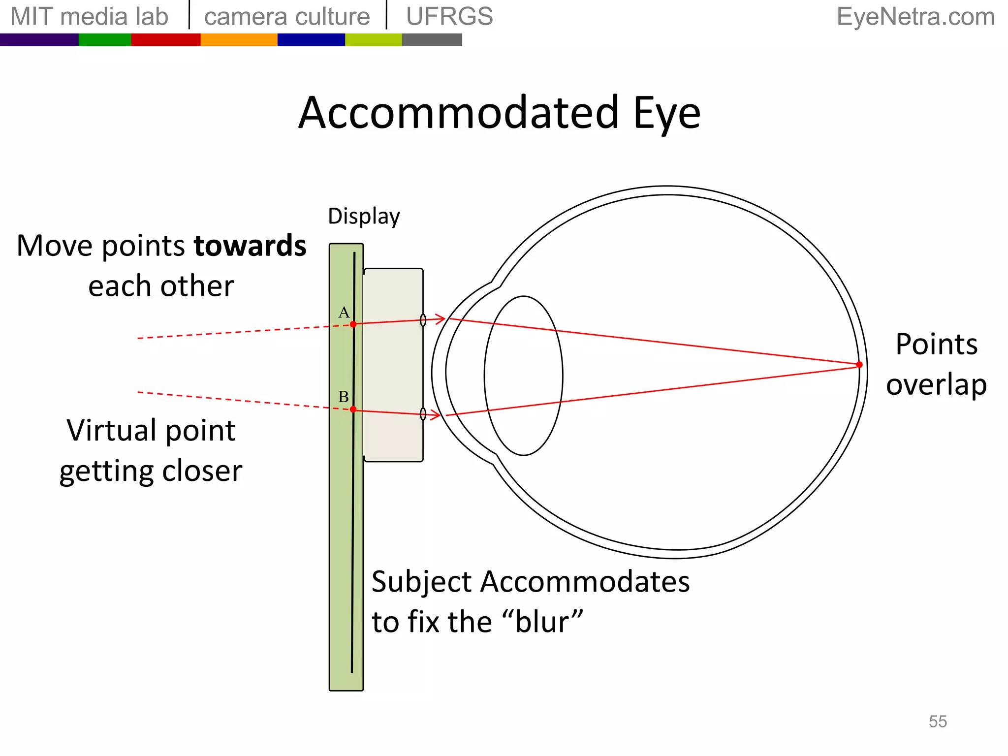
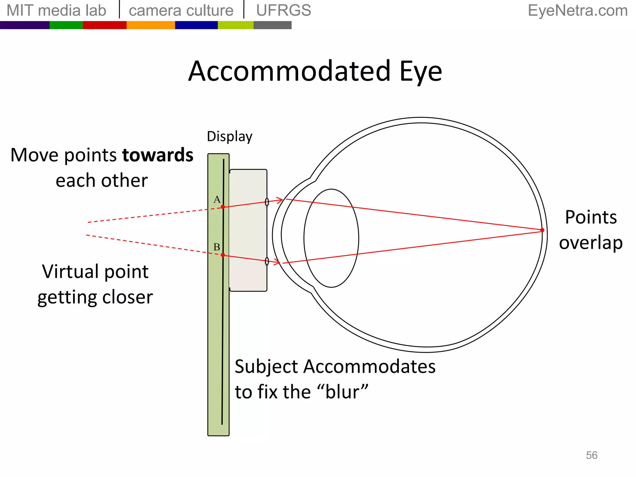
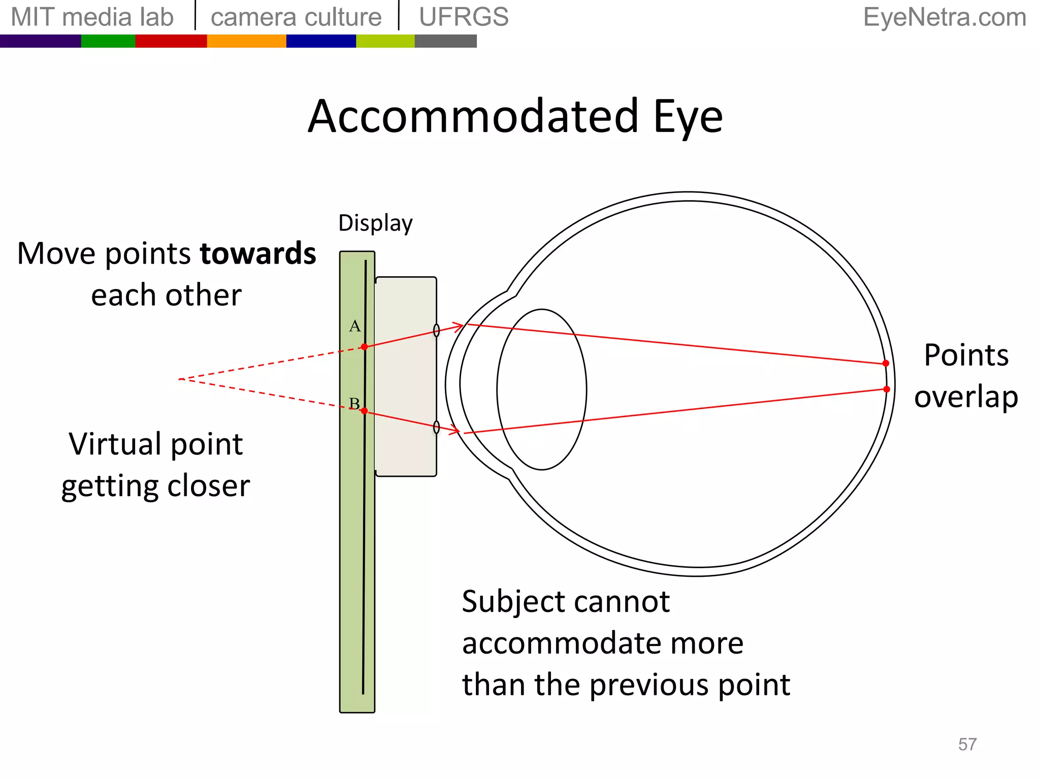
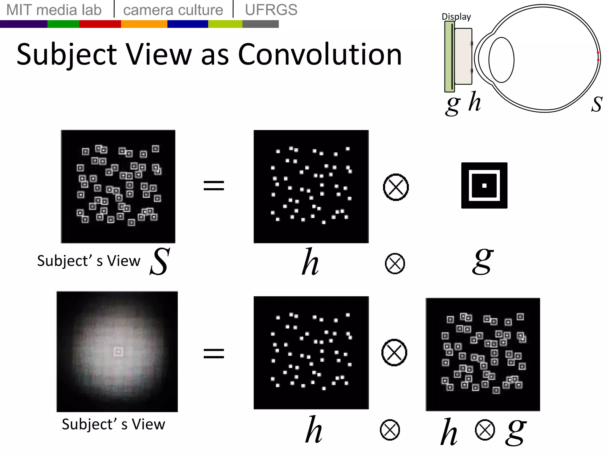
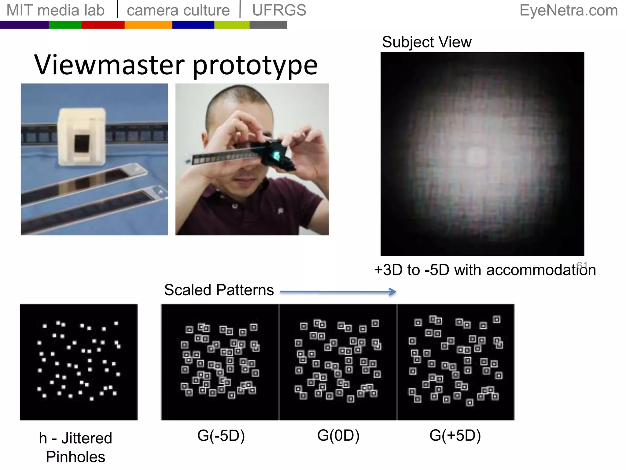
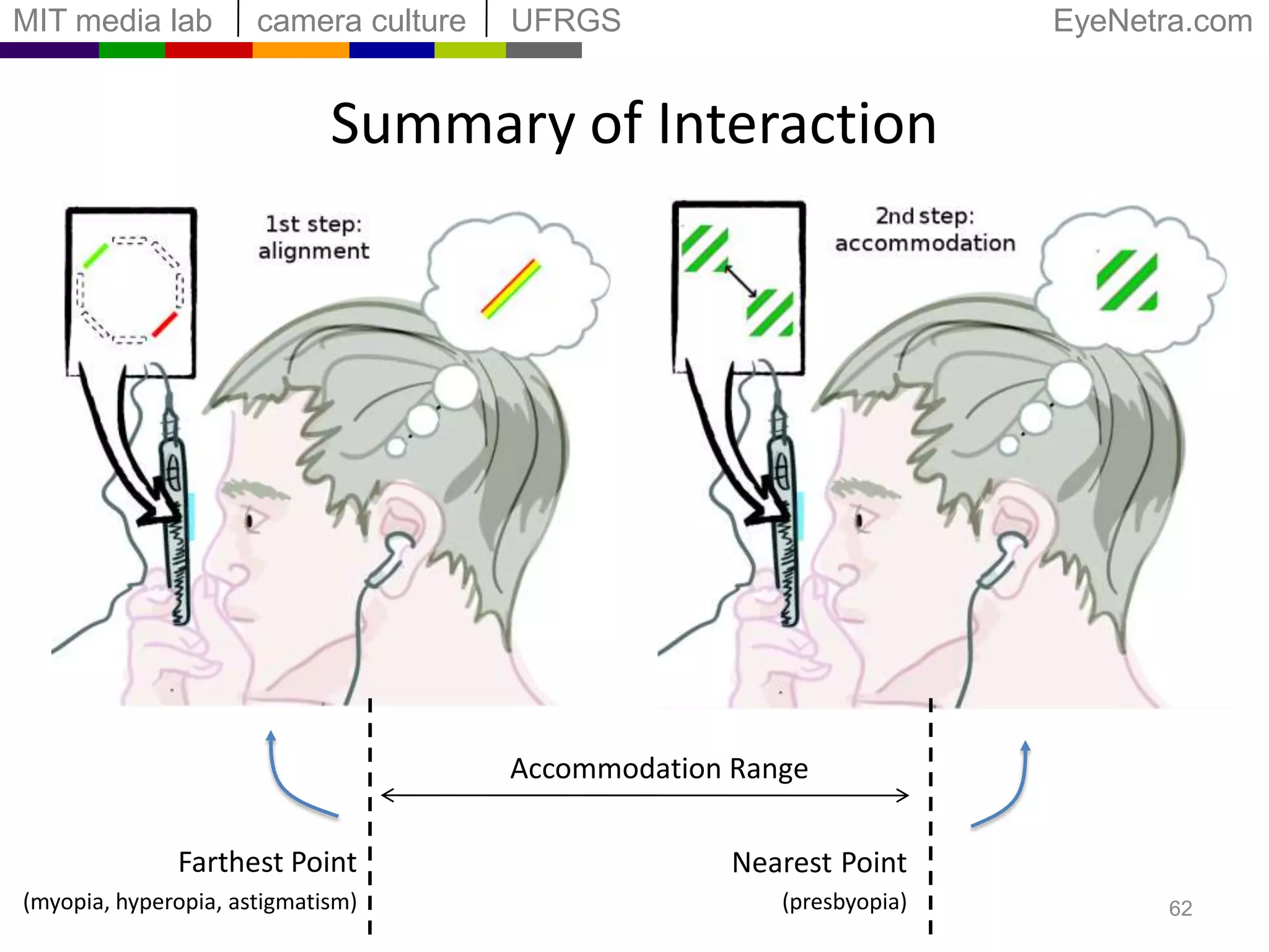
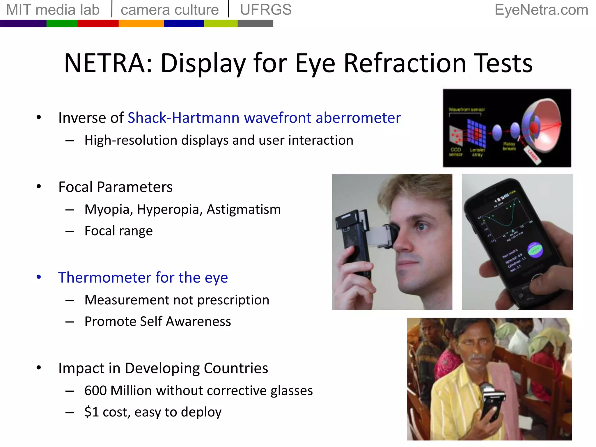
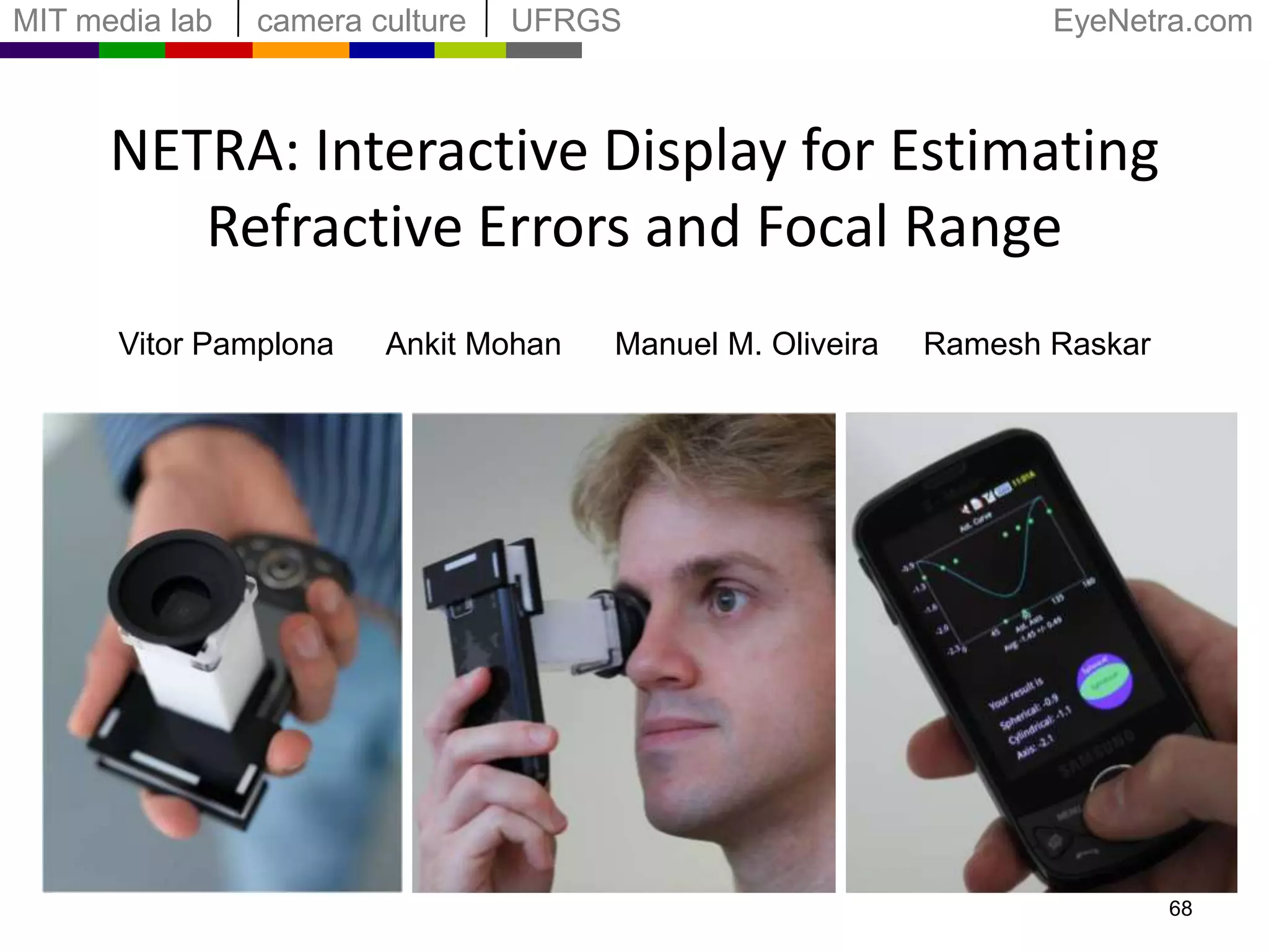

1) NETRA is an interactive display that estimates refractive errors and focal range by taking the inverse approach of the Shack-Hartmann wavefront sensor. It uses high-resolution displays and user interaction rather than lasers and sensors. 2) The user interacts with patterns on the display to measure their farthest and nearest focal points, allowing NETRA to determine refractive errors like myopia, hyperopia, and astigmatism, as well as the overall focal range. 3) NETRA has applications in low-cost, portable eye exams that could improve eye care access in developing countries. Over 600 million people lack corrective glasses due to limited resources.