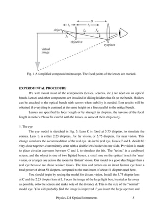
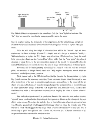
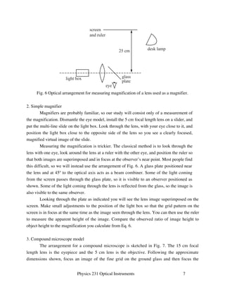
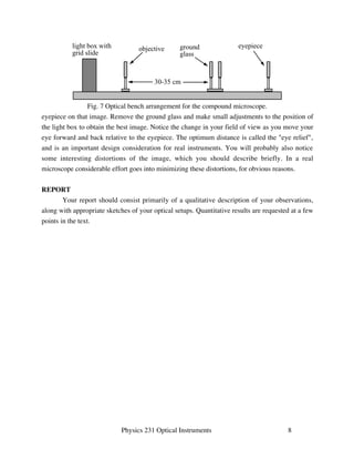
SlideShare a Scribd company logo
1 of 8
Download to read offline
Optical Instruments 
Scientists study the world as it is, engineers create the world that never has been. 
Theodore von Karman (1881-1963) 
OBJECTIVES 
To examine the operation of some simple optical instruments: eye glasses, magnifier, and 
compound microscope. 
THEORY 
A normal human eye forms sharp images of objects between about 25 cm and infinity. 
Many individuals, however, have visual defects which hinder their ability to see clearly over the 
full range, and with advancing years essentially everyone will experience a reduction in focusing 
ability. Eye glasses, first known from about 1300, are a great aid in such cases. Of course, even 
the best eyes have limited resolution, and cannot adequately image very small or very distant 
objects. For that people invented microscopes and telescopes, with revolutionary impact on 
science and technology. In this lab session you will briefly examine the operation of some of 
these devices, starting with the eye itself. 
The eye of a typical vertebrate consists of one or two lenses in front of a sheet of neural 
material that converts the optical image to electrical signals for further processing elsewhere. In 
humans most of the refracting power is due to the front surface (cornea) of the eyeball. The 
"crystalline lens" (which is not crystalline) sits directly behind the cornea, inside the eye. It is 
equipped with muscles that can change its effective focal length, allowing the eye to focus at the 
desired plane. Unlike a camera, the distance between the lens and the image plane is fixed, so all 
the accommodation is the result of changes in the crystalline lens. 
The optical system of the eye is not particularly good, so the resulting image is somewhat 
distorted. Many types of distortion are corrected when the image is processed in the brain, but 
some defects are so severe as to hinder vision. The most common problem is nearsightedness or 
farsightedness: The inability to focus on far away or nearby objects, respectively. Figure 1 
illustrates the problem for a near-sighted (myopic) eye. 
If we approximate the optics of the eye by a thin lens, we can understand these refractive 
problems with the aid of the Gaussian lens formula 
1 
so 
+ 
1 
si 
= 
1 
fe 
(1)
25 cm 
near 
point 
range of clear vision 
normal 
eye 
8 cm 
near 
point 
50 cm 
far 
point 
myopic 
eye 
corrected 
myopic 
eye 
Fig. 1 Comparison of a normal, myopic and corrected myopic eye. The far point and near point 
represent the limits of clear vision. 
where so is the distance from object to lens, si is the distance from the lens to the focused image 
and fe is the focal length of the lens. The image distance si must be the same as the length, d, of 
the eye for a sharp image to be produced on the retina. In a nearsighted person, the lens is too 
strong (fe is too small) to form an image at d when so is large. Conversely, in a farsighted person 
the lens is too weak (fe is too large) to form an image when so is small. Since the size of the eye 
is fixed, we need to change f. This can be done by surgery or with a lens placed in front of the 
eye. 
To correct a nearsighted eye, we use a diverging lens to partially counteract the focusing 
of the eye lens, as suggested in Fig. 1. Within the thin lens approximation, the effective focal 
length f' of two lenses separated by much less than their individual focal lengths is given by 
Physics 231 Optical Instruments 2 
1 
f  
= 
1 
fe 
+ 
1 
f c 
(2) 
where fc refers to the corrective lens. We want to pick f' so that 
1 
 
+ 
1 
d 
= 
1 
f  
= 
1 
f e 
+ 
1 
f c 
(3) 
Of course we do not know d (patients usually object to a direct measurement), but we can 
measure the farthest distance at which an object is in clear focus for the bare eye. Calling this 
distance sf, we obtain
50 cm 
near 
point 
presbyopic 
eye 
presbyopic 
eye with 
bifocals 
75 cm 
38 cm 25 cm 
Fig. 2 Presbyopia (limited accommodation) and correction with a bifocal lens. 
Physics 231 Optical Instruments 3 
150 cm 
far 
point 
1 
s f 
+ 
1 
d 
= 
1 
f e 
(4) 
Solving (3) and (4), we find fc = -sf. As expected, we need a negative lens. A similar argument 
will give the correction for a farsighted eye in terms of the closest distance at which the bare eye 
can focus. 
If the variation in focal length of the crystalline lens is normal, a single lens is adequate to 
restore normal vision. With age, however, the crystalline lens gradually becomes rigid and 
accommodation is lost, a defect known as presbyopia. The solution is to use different lenses for 
near and far vision, often in the form of bifocals as shown in Fig. 2. 
Another common defect is astigmatism, in which the eye is unable to sharply focus an 
entire image at any distance. Astigmatism is usually produced by an asymmetry of the cornea 
which causes the effective focal length of the eye to be different for groups of rays in the 
horizontal and vertical planes. A lens in the form of a cylinder section (rather than a sphere 
section) will focus only in one plane, and can sometimes be used to correct astigmatism. The 
correction is found in the same way as for spherical lenses. 
A single-lens magnifier is the logical extension of eye glasses. In trying to examine fine 
details we bring an object closer to our eyes so that it subtends a larger angle, but eventually we 
reach the point of closest focus and there is no further gain. A short focal length lens placed in 
front of the eye allows us to continue this process so that the object appears closer and hence 
larger. Referring to Fig. 3, we make so smaller than the focal length so that the lens forms a 
virtual image at the near point of the eye. The eye forms a real image on the retina subtending an 
angle ' which is larger than the angle  without the lens. A reasonable definition of 
magnification would be
so 
y 
object 
Fig. 3 A simple lens used as a magnifier. 
 (7) 
θ 
θ' 
-si 
Physics 231 Optical Instruments 4 
y 
object 
25 cm 
y' 
virtual 
image 
25 cm 
M = 


y / si 
y /25cm 
(5) 
Using the simple lens formula and the fact that si is negative for a virtual image finally yields 
M = 1 + 
25cm 
f 
(6) 
where f is the focal length of the magnifying lens. 
The magnification available with a single lens is limited because the lens becomes too 
small to handle. The compound microscope, shown in simplified form in Fig. 4, allows much 
higher magnification with lenses of manageable dimensions. The object to be examined is placed 
just beyond the focal point of the objective lens, so that a real magnified image is formed as 
shown. The eyepiece lens is positioned so as to form a magnified virtual image of that real 
image. The overall magnification is the product of the objective and eyepiece magnifications, 
M = MoMe = 
si 
so 
1 + 
25cm 
fe 


where the minus sign indicates that the image is inverted. The tube length of the microscope 
body, D in Fig. 4, is standardized so objective and eye piece lenses are often marked with their 
magnification. Other features of practical importance are discussed in standard textbooks.
so si 
fo 
object 
virtual 
image 
Fig. 4 A simplified compound microscope. The focal points of the lenses are marked. 
EXPERIMENTAL PROCEDURE 
D 
fo f e 
objective 
eyepiece 
We will mount most of the components (lenses, screens, etc.) we need on an optical 
bench. Lenses and other components are installed in sliding holders that fit on the bench. Holders 
can be attached to the optical bench with screws when stability is needed. Best results will be 
obtained if everything is centered at the same height on a line parallel to the optical bench. 
Lenses are specified by focal length or by strength in diopters, the inverse of the focal 
length in meters. Please be careful with the lenses, as some of them chip easily. 
Physics 231 Optical Instruments 5 
1. The eye 
The eye model is sketched in Fig. 5. Lens C is fixed at 5.75 diopters, to simulate the 
cornea. Lens L is either 2.25 diopters, for far vision, or 5.75 diopters, for near vision. This 
change simulates the accommodation of the real eye. As in the real eye, lenses C and L should be 
very close together, conveniently done with a double lens holder on one slide. Provision is made 
to place circular apertures between C and L to simulate the iris. The retina is a cardboard 
screen, and the object is one of two lighted boxes, a small one on the optical bench for 'near' 
vision, or a larger one across the room for 'distant' vision. Our model is a good deal bigger than a 
real eye because we chose weaker lenses. The lens and cornea on an intact human eye have a 
total power of about 58 diopters, compared to the maximum of about 11 diopters used here. 
You should begin by setting the model for distant vision. Install the 5.75 diopter lens 
at C and the 2.25 diopter lens at L. Focus the image of the large light box, located as far away 
as possible, onto the screen and make note of the distance d. This is the size of the “normal” 
model eye. You will probably find the image is improved if you insert the large aperture and
lens L 
lens 
d 
screen 
retina 
lens C 
cornea 
corrective 
lens 
leave it in place during the remainder of the experiment. Is the retinal image upright or 
inverted? Reversed? Since these terms are somewhat ambiguous, be sure to explain what you 
mean. 
Next we will study the range of distances over which the normal eye we have 
constructed can focus an image. With the 2.25 diopter lens at L, the eye is focused at infinity. 
Without changing d, replace the 2.25 diopter lens at L with a 5.75 diopter lens. Using the small 
light box on the slider and the 'crossed-line' object slide, find the near point, the closest 
distance of sharp focus. Is the accommodation range of the model eye reasonably close to 
normal? For later use, you should also note the ratio of image size to object size at the near point. 
Now make the eye nearsighted by increasing d to a value of 16-17 cm. Find the new near 
point, and the ratio of image size to object size. Why might a nearsighted person prefer to 
examine a small object without glasses on? 
Next, change back to the 2.25 diopter lens, find the far point for the nearsighted eye (sf in 
Eq. 4), and compute the necessary correction. Using a separate holder, place the corrective lens 
close to the front of the eye, to simulate eyeglasses or a contact lens. Is the image of the far 
object now reasonably focused? Does the image change if the correction lens is close to the eye 
or a few centimeters away? Install the 5.75 diopter lens at L for near vision, and find the 
corrected near point. Is the corrected accommodation roughly the same as in the normal 
model? 
Our study of astigmatism will be qualitative. Remove the corrective lens, and set d to the 
normal value you found at the beginning of the experiment. Obtain a sharp image of the near 
object on the screen. Now place the cylinder lens in front of the eye, where the corrective lens 
was. Describe qualitatively what happens to the image when you rotate the cylinder lens. With 
the lenses fixed, what happens to the image when you move the retina? You may also find it 
interesting to place the cylinder lens in front of you own eye, to better understand why 
astigmatism must be corrected for adequate vision. 
Physics 231 Optical Instruments 6 
light box with 
object slide 
Fig. 5 Optical bench arrangement for the model eye. Only the “near” light box is shown. The 
“far” light box should be placed as far away as possible, across the room.
screen 
and ruler 
25 cm desk lamp 
glass 
plate 
light box 
eye 
Fig. 6 Optical arrangement for measuring magnification of a lens used as a magnifier. 
Physics 231 Optical Instruments 7 
2. Simple magnifier 
Magnifiers are probably familiar, so our study will consist only of a measurement of 
the magnification. Dismantle the eye model, install the 5 cm focal length lens on a slider, and 
put the multi-line slide on the light box. Look through the lens, with your eye close to it, and 
position the light box close to the opposite side of the lens so you see a clearly focused, 
magnified virtual image of the slide. 
Measuring the magnification is trickier. The classical method is to look through the 
lens with one eye, look around the lens at a ruler with the other eye, and position the ruler so 
that both images are superimposed and in focus at the observer’s near point. Most people find 
this difficult, so we will instead use the arrangement of Fig. 6. A glass plate positioned near 
the lens and at 45º to the optical axis acts as a beam combiner. Some of the light coming 
from the screen passes through the glass plate, so it is visible to an observer positioned as 
shown. Some of the light coming through the lens is reflected from the glass, so the image is 
also visible to the same observer. 
Looking through the plate as indicated you will see the lens image superimposed on the 
screen. Make small adjustments to the position of the light box so that the grid pattern on the 
screen is in focus at the same time as the image seen through the lens. You can then use the ruler 
to measure the apparent height of the image. Compare the observed ratio of image height to 
object height to the magnification you calculate from Eq. 6. 
3. Compound microscope model 
The arrangement for a compound microscope is sketched in Fig. 7. The 15 cm focal 
length lens is the eyepiece and the 5 cm lens is the objective. Following the approximate 
dimensions shown, focus an image of the fine grid on the ground glass and then focus the
ground eyepiece 
glass 
light box with objective 
grid slide 
30-35 cm 
Fig. 7 Optical bench arrangement for the compound microscope. 
eyepiece on that image. Remove the ground glass and make small adjustments to the position of 
the light box to obtain the best image. Notice the change in your field of view as you move your 
eye forward and back relative to the eyepiece. The optimum distance is called the eye relief, 
and is an important design consideration for real instruments. You will probably also notice 
some interesting distortions of the image, which you should describe briefly. In a real 
microscope considerable effort goes into minimizing these distortions, for obvious reasons. 
Physics 231 Optical Instruments 8 
REPORT 
Your report should consist primarily of a qualitative description of your observations, 
along with appropriate sketches of your optical setups. Quantitative results are requested at a few 
points in the text.

More Related Content

What's hot

chapter25 Optical Instruments
chapter25 Optical Instrumentschapter25 Optical Instruments
chapter25 Optical InstrumentsJames Evangelos
 
Optical instruments
Optical instrumentsOptical instruments
Optical instrumentsMussaOmary3
 
Optics of contact lens
Optics of contact lensOptics of contact lens
Optics of contact lensAayush Chandan
 
soft contact lens optics and soft contact lens materials
soft contact lens optics and soft contact lens materialssoft contact lens optics and soft contact lens materials
soft contact lens optics and soft contact lens materialsBipin Koirala
 
Module 4 optical instruments
Module 4 optical instrumentsModule 4 optical instruments
Module 4 optical instrumentsdionesioable
 
Optical equipment
Optical equipmentOptical equipment
Optical equipmentroesyah
 
Spectacle prescription
Spectacle prescriptionSpectacle prescription
Spectacle prescriptionRicha Naik
 
introduction to learn laser in refractive erros
introduction to learn laser in refractive errosintroduction to learn laser in refractive erros
introduction to learn laser in refractive errosGazy Khatmi
 
Low Vision Near Systems-Microscopes,Magnifiers & Electronic systems
Low Vision Near Systems-Microscopes,Magnifiers & Electronic systemsLow Vision Near Systems-Microscopes,Magnifiers & Electronic systems
Low Vision Near Systems-Microscopes,Magnifiers & Electronic systemsHarsh Jain
 
New microsoft power point presentation
New microsoft power point presentationNew microsoft power point presentation
New microsoft power point presentationJainull Abedin
 
Optics of contact lens and nomenclature copy [repaired] (1)
Optics of contact lens and nomenclature   copy [repaired] (1)Optics of contact lens and nomenclature   copy [repaired] (1)
Optics of contact lens and nomenclature copy [repaired] (1)Manjusha Lakshmi
 
Ophthalmic Prisms: Prismatic Effects and Decentration
Ophthalmic Prisms: Prismatic Effects and DecentrationOphthalmic Prisms: Prismatic Effects and Decentration
Ophthalmic Prisms: Prismatic Effects and DecentrationRabindraAdhikary
 
Tailored Displays to Compensate for Visual Aberrations - SIGGRAPH Presentation
Tailored Displays to Compensate for Visual Aberrations - SIGGRAPH PresentationTailored Displays to Compensate for Visual Aberrations - SIGGRAPH Presentation
Tailored Displays to Compensate for Visual Aberrations - SIGGRAPH PresentationVitor Pamplona
 
Low vision aid
Low vision aidLow vision aid
Low vision aidSSSIHMS-PG
 

What's hot (20)

chapter25 Optical Instruments
chapter25 Optical Instrumentschapter25 Optical Instruments
chapter25 Optical Instruments
 
Optical instruments
Optical instrumentsOptical instruments
Optical instruments
 
Optics of contact lens
Optics of contact lensOptics of contact lens
Optics of contact lens
 
soft contact lens optics and soft contact lens materials
soft contact lens optics and soft contact lens materialssoft contact lens optics and soft contact lens materials
soft contact lens optics and soft contact lens materials
 
Module 4 optical instruments
Module 4 optical instrumentsModule 4 optical instruments
Module 4 optical instruments
 
Optical equipment
Optical equipmentOptical equipment
Optical equipment
 
Spectacle prescription
Spectacle prescriptionSpectacle prescription
Spectacle prescription
 
introduction to learn laser in refractive erros
introduction to learn laser in refractive errosintroduction to learn laser in refractive erros
introduction to learn laser in refractive erros
 
Low Vision Near Systems-Microscopes,Magnifiers & Electronic systems
Low Vision Near Systems-Microscopes,Magnifiers & Electronic systemsLow Vision Near Systems-Microscopes,Magnifiers & Electronic systems
Low Vision Near Systems-Microscopes,Magnifiers & Electronic systems
 
New microsoft power point presentation
New microsoft power point presentationNew microsoft power point presentation
New microsoft power point presentation
 
Optics of contact lens and nomenclature copy [repaired] (1)
Optics of contact lens and nomenclature   copy [repaired] (1)Optics of contact lens and nomenclature   copy [repaired] (1)
Optics of contact lens and nomenclature copy [repaired] (1)
 
Optics of contact lenses by ankit varshney
Optics of contact lenses by ankit varshneyOptics of contact lenses by ankit varshney
Optics of contact lenses by ankit varshney
 
Lensometer
LensometerLensometer
Lensometer
 
EDOF IOL
EDOF IOLEDOF IOL
EDOF IOL
 
Ophthalmic Prisms: Prismatic Effects and Decentration
Ophthalmic Prisms: Prismatic Effects and DecentrationOphthalmic Prisms: Prismatic Effects and Decentration
Ophthalmic Prisms: Prismatic Effects and Decentration
 
Magnification
MagnificationMagnification
Magnification
 
Tailored Displays to Compensate for Visual Aberrations - SIGGRAPH Presentation
Tailored Displays to Compensate for Visual Aberrations - SIGGRAPH PresentationTailored Displays to Compensate for Visual Aberrations - SIGGRAPH Presentation
Tailored Displays to Compensate for Visual Aberrations - SIGGRAPH Presentation
 
Contact lens
Contact lensContact lens
Contact lens
 
Vision
VisionVision
Vision
 
Low vision aid
Low vision aidLow vision aid
Low vision aid
 

Similar to Optical

Contact Lenses and LVAs.pptx
Contact Lenses and LVAs.pptxContact Lenses and LVAs.pptx
Contact Lenses and LVAs.pptxZaid Azhar
 
Chapter Light: Grade 10 Physics
Chapter Light: Grade 10 PhysicsChapter Light: Grade 10 Physics
Chapter Light: Grade 10 PhysicsLearn Infinite
 
Lens Focal Lenght Thin Report by Fildia Putri
Lens Focal Lenght Thin Report by Fildia PutriLens Focal Lenght Thin Report by Fildia Putri
Lens Focal Lenght Thin Report by Fildia PutriIndy Puteri
 
optics.Dr.Mutaz.ppt
optics.Dr.Mutaz.pptoptics.Dr.Mutaz.ppt
optics.Dr.Mutaz.pptAdel930879
 
Eye as an optical system.
Eye as an optical system.Eye as an optical system.
Eye as an optical system.AmritJha7
 
Physics Investagatory Project
Physics Investagatory ProjectPhysics Investagatory Project
Physics Investagatory ProjectVikash Prasad
 
Sesión de Laboratorio 6: Lentes Ópticas
Sesión de Laboratorio 6: Lentes ÓpticasSesión de Laboratorio 6: Lentes Ópticas
Sesión de Laboratorio 6: Lentes ÓpticasJavier García Molleja
 
Human eye and colourful world
Human eye and colourful worldHuman eye and colourful world
Human eye and colourful worldShivakumarHP
 
Optics of ametropia
Optics of ametropiaOptics of ametropia
Optics of ametropiaSSSIHMS-PG
 
Binocular Indirect Ophthalmoscopy
Binocular Indirect OphthalmoscopyBinocular Indirect Ophthalmoscopy
Binocular Indirect Ophthalmoscopyabhishek ghelani
 
Refrective errors of eyes
Refrective errors of eyesRefrective errors of eyes
Refrective errors of eyesRaghu Veer
 

Similar to Optical (20)

Contact Lenses and LVAs.pptx
Contact Lenses and LVAs.pptxContact Lenses and LVAs.pptx
Contact Lenses and LVAs.pptx
 
Chapter Light: Grade 10 Physics
Chapter Light: Grade 10 PhysicsChapter Light: Grade 10 Physics
Chapter Light: Grade 10 Physics
 
optical instruments.pdf
optical instruments.pdfoptical instruments.pdf
optical instruments.pdf
 
Vision
VisionVision
Vision
 
Lens Focal Lenght Thin Report by Fildia Putri
Lens Focal Lenght Thin Report by Fildia PutriLens Focal Lenght Thin Report by Fildia Putri
Lens Focal Lenght Thin Report by Fildia Putri
 
optics.Dr.Mutaz.ppt
optics.Dr.Mutaz.pptoptics.Dr.Mutaz.ppt
optics.Dr.Mutaz.ppt
 
Eye as an optical system.
Eye as an optical system.Eye as an optical system.
Eye as an optical system.
 
Physics Investagatory Project
Physics Investagatory ProjectPhysics Investagatory Project
Physics Investagatory Project
 
Ophthalmology 5th year, 4th lecture (Dr. Tara)
Ophthalmology 5th year, 4th lecture (Dr. Tara)Ophthalmology 5th year, 4th lecture (Dr. Tara)
Ophthalmology 5th year, 4th lecture (Dr. Tara)
 
Optometer.pptx
Optometer.pptxOptometer.pptx
Optometer.pptx
 
Module No. 38
Module No. 38Module No. 38
Module No. 38
 
Sesión de Laboratorio 6: Lentes Ópticas
Sesión de Laboratorio 6: Lentes ÓpticasSesión de Laboratorio 6: Lentes Ópticas
Sesión de Laboratorio 6: Lentes Ópticas
 
Telescopes
TelescopesTelescopes
Telescopes
 
basics of microscope - part 1
basics of microscope - part 1basics of microscope - part 1
basics of microscope - part 1
 
Human eye and colourful world
Human eye and colourful worldHuman eye and colourful world
Human eye and colourful world
 
Optics of ametropia
Optics of ametropiaOptics of ametropia
Optics of ametropia
 
Human eye
Human eyeHuman eye
Human eye
 
Compound microscope
Compound microscopeCompound microscope
Compound microscope
 
Binocular Indirect Ophthalmoscopy
Binocular Indirect OphthalmoscopyBinocular Indirect Ophthalmoscopy
Binocular Indirect Ophthalmoscopy
 
Refrective errors of eyes
Refrective errors of eyesRefrective errors of eyes
Refrective errors of eyes
 

Optical

  • 1. Optical Instruments Scientists study the world as it is, engineers create the world that never has been. Theodore von Karman (1881-1963) OBJECTIVES To examine the operation of some simple optical instruments: eye glasses, magnifier, and compound microscope. THEORY A normal human eye forms sharp images of objects between about 25 cm and infinity. Many individuals, however, have visual defects which hinder their ability to see clearly over the full range, and with advancing years essentially everyone will experience a reduction in focusing ability. Eye glasses, first known from about 1300, are a great aid in such cases. Of course, even the best eyes have limited resolution, and cannot adequately image very small or very distant objects. For that people invented microscopes and telescopes, with revolutionary impact on science and technology. In this lab session you will briefly examine the operation of some of these devices, starting with the eye itself. The eye of a typical vertebrate consists of one or two lenses in front of a sheet of neural material that converts the optical image to electrical signals for further processing elsewhere. In humans most of the refracting power is due to the front surface (cornea) of the eyeball. The "crystalline lens" (which is not crystalline) sits directly behind the cornea, inside the eye. It is equipped with muscles that can change its effective focal length, allowing the eye to focus at the desired plane. Unlike a camera, the distance between the lens and the image plane is fixed, so all the accommodation is the result of changes in the crystalline lens. The optical system of the eye is not particularly good, so the resulting image is somewhat distorted. Many types of distortion are corrected when the image is processed in the brain, but some defects are so severe as to hinder vision. The most common problem is nearsightedness or farsightedness: The inability to focus on far away or nearby objects, respectively. Figure 1 illustrates the problem for a near-sighted (myopic) eye. If we approximate the optics of the eye by a thin lens, we can understand these refractive problems with the aid of the Gaussian lens formula 1 so + 1 si = 1 fe (1)
  • 2. 25 cm near point range of clear vision normal eye 8 cm near point 50 cm far point myopic eye corrected myopic eye Fig. 1 Comparison of a normal, myopic and corrected myopic eye. The far point and near point represent the limits of clear vision. where so is the distance from object to lens, si is the distance from the lens to the focused image and fe is the focal length of the lens. The image distance si must be the same as the length, d, of the eye for a sharp image to be produced on the retina. In a nearsighted person, the lens is too strong (fe is too small) to form an image at d when so is large. Conversely, in a farsighted person the lens is too weak (fe is too large) to form an image when so is small. Since the size of the eye is fixed, we need to change f. This can be done by surgery or with a lens placed in front of the eye. To correct a nearsighted eye, we use a diverging lens to partially counteract the focusing of the eye lens, as suggested in Fig. 1. Within the thin lens approximation, the effective focal length f' of two lenses separated by much less than their individual focal lengths is given by Physics 231 Optical Instruments 2 1 f = 1 fe + 1 f c (2) where fc refers to the corrective lens. We want to pick f' so that 1 + 1 d = 1 f = 1 f e + 1 f c (3) Of course we do not know d (patients usually object to a direct measurement), but we can measure the farthest distance at which an object is in clear focus for the bare eye. Calling this distance sf, we obtain
  • 3. 50 cm near point presbyopic eye presbyopic eye with bifocals 75 cm 38 cm 25 cm Fig. 2 Presbyopia (limited accommodation) and correction with a bifocal lens. Physics 231 Optical Instruments 3 150 cm far point 1 s f + 1 d = 1 f e (4) Solving (3) and (4), we find fc = -sf. As expected, we need a negative lens. A similar argument will give the correction for a farsighted eye in terms of the closest distance at which the bare eye can focus. If the variation in focal length of the crystalline lens is normal, a single lens is adequate to restore normal vision. With age, however, the crystalline lens gradually becomes rigid and accommodation is lost, a defect known as presbyopia. The solution is to use different lenses for near and far vision, often in the form of bifocals as shown in Fig. 2. Another common defect is astigmatism, in which the eye is unable to sharply focus an entire image at any distance. Astigmatism is usually produced by an asymmetry of the cornea which causes the effective focal length of the eye to be different for groups of rays in the horizontal and vertical planes. A lens in the form of a cylinder section (rather than a sphere section) will focus only in one plane, and can sometimes be used to correct astigmatism. The correction is found in the same way as for spherical lenses. A single-lens magnifier is the logical extension of eye glasses. In trying to examine fine details we bring an object closer to our eyes so that it subtends a larger angle, but eventually we reach the point of closest focus and there is no further gain. A short focal length lens placed in front of the eye allows us to continue this process so that the object appears closer and hence larger. Referring to Fig. 3, we make so smaller than the focal length so that the lens forms a virtual image at the near point of the eye. The eye forms a real image on the retina subtending an angle ' which is larger than the angle without the lens. A reasonable definition of magnification would be
  • 4. so y object Fig. 3 A simple lens used as a magnifier. (7) θ θ' -si Physics 231 Optical Instruments 4 y object 25 cm y' virtual image 25 cm M = y / si y /25cm (5) Using the simple lens formula and the fact that si is negative for a virtual image finally yields M = 1 + 25cm f (6) where f is the focal length of the magnifying lens. The magnification available with a single lens is limited because the lens becomes too small to handle. The compound microscope, shown in simplified form in Fig. 4, allows much higher magnification with lenses of manageable dimensions. The object to be examined is placed just beyond the focal point of the objective lens, so that a real magnified image is formed as shown. The eyepiece lens is positioned so as to form a magnified virtual image of that real image. The overall magnification is the product of the objective and eyepiece magnifications, M = MoMe = si so 1 + 25cm fe where the minus sign indicates that the image is inverted. The tube length of the microscope body, D in Fig. 4, is standardized so objective and eye piece lenses are often marked with their magnification. Other features of practical importance are discussed in standard textbooks.
  • 5. so si fo object virtual image Fig. 4 A simplified compound microscope. The focal points of the lenses are marked. EXPERIMENTAL PROCEDURE D fo f e objective eyepiece We will mount most of the components (lenses, screens, etc.) we need on an optical bench. Lenses and other components are installed in sliding holders that fit on the bench. Holders can be attached to the optical bench with screws when stability is needed. Best results will be obtained if everything is centered at the same height on a line parallel to the optical bench. Lenses are specified by focal length or by strength in diopters, the inverse of the focal length in meters. Please be careful with the lenses, as some of them chip easily. Physics 231 Optical Instruments 5 1. The eye The eye model is sketched in Fig. 5. Lens C is fixed at 5.75 diopters, to simulate the cornea. Lens L is either 2.25 diopters, for far vision, or 5.75 diopters, for near vision. This change simulates the accommodation of the real eye. As in the real eye, lenses C and L should be very close together, conveniently done with a double lens holder on one slide. Provision is made to place circular apertures between C and L to simulate the iris. The retina is a cardboard screen, and the object is one of two lighted boxes, a small one on the optical bench for 'near' vision, or a larger one across the room for 'distant' vision. Our model is a good deal bigger than a real eye because we chose weaker lenses. The lens and cornea on an intact human eye have a total power of about 58 diopters, compared to the maximum of about 11 diopters used here. You should begin by setting the model for distant vision. Install the 5.75 diopter lens at C and the 2.25 diopter lens at L. Focus the image of the large light box, located as far away as possible, onto the screen and make note of the distance d. This is the size of the “normal” model eye. You will probably find the image is improved if you insert the large aperture and
  • 6. lens L lens d screen retina lens C cornea corrective lens leave it in place during the remainder of the experiment. Is the retinal image upright or inverted? Reversed? Since these terms are somewhat ambiguous, be sure to explain what you mean. Next we will study the range of distances over which the normal eye we have constructed can focus an image. With the 2.25 diopter lens at L, the eye is focused at infinity. Without changing d, replace the 2.25 diopter lens at L with a 5.75 diopter lens. Using the small light box on the slider and the 'crossed-line' object slide, find the near point, the closest distance of sharp focus. Is the accommodation range of the model eye reasonably close to normal? For later use, you should also note the ratio of image size to object size at the near point. Now make the eye nearsighted by increasing d to a value of 16-17 cm. Find the new near point, and the ratio of image size to object size. Why might a nearsighted person prefer to examine a small object without glasses on? Next, change back to the 2.25 diopter lens, find the far point for the nearsighted eye (sf in Eq. 4), and compute the necessary correction. Using a separate holder, place the corrective lens close to the front of the eye, to simulate eyeglasses or a contact lens. Is the image of the far object now reasonably focused? Does the image change if the correction lens is close to the eye or a few centimeters away? Install the 5.75 diopter lens at L for near vision, and find the corrected near point. Is the corrected accommodation roughly the same as in the normal model? Our study of astigmatism will be qualitative. Remove the corrective lens, and set d to the normal value you found at the beginning of the experiment. Obtain a sharp image of the near object on the screen. Now place the cylinder lens in front of the eye, where the corrective lens was. Describe qualitatively what happens to the image when you rotate the cylinder lens. With the lenses fixed, what happens to the image when you move the retina? You may also find it interesting to place the cylinder lens in front of you own eye, to better understand why astigmatism must be corrected for adequate vision. Physics 231 Optical Instruments 6 light box with object slide Fig. 5 Optical bench arrangement for the model eye. Only the “near” light box is shown. The “far” light box should be placed as far away as possible, across the room.
  • 7. screen and ruler 25 cm desk lamp glass plate light box eye Fig. 6 Optical arrangement for measuring magnification of a lens used as a magnifier. Physics 231 Optical Instruments 7 2. Simple magnifier Magnifiers are probably familiar, so our study will consist only of a measurement of the magnification. Dismantle the eye model, install the 5 cm focal length lens on a slider, and put the multi-line slide on the light box. Look through the lens, with your eye close to it, and position the light box close to the opposite side of the lens so you see a clearly focused, magnified virtual image of the slide. Measuring the magnification is trickier. The classical method is to look through the lens with one eye, look around the lens at a ruler with the other eye, and position the ruler so that both images are superimposed and in focus at the observer’s near point. Most people find this difficult, so we will instead use the arrangement of Fig. 6. A glass plate positioned near the lens and at 45º to the optical axis acts as a beam combiner. Some of the light coming from the screen passes through the glass plate, so it is visible to an observer positioned as shown. Some of the light coming through the lens is reflected from the glass, so the image is also visible to the same observer. Looking through the plate as indicated you will see the lens image superimposed on the screen. Make small adjustments to the position of the light box so that the grid pattern on the screen is in focus at the same time as the image seen through the lens. You can then use the ruler to measure the apparent height of the image. Compare the observed ratio of image height to object height to the magnification you calculate from Eq. 6. 3. Compound microscope model The arrangement for a compound microscope is sketched in Fig. 7. The 15 cm focal length lens is the eyepiece and the 5 cm lens is the objective. Following the approximate dimensions shown, focus an image of the fine grid on the ground glass and then focus the
  • 8. ground eyepiece glass light box with objective grid slide 30-35 cm Fig. 7 Optical bench arrangement for the compound microscope. eyepiece on that image. Remove the ground glass and make small adjustments to the position of the light box to obtain the best image. Notice the change in your field of view as you move your eye forward and back relative to the eyepiece. The optimum distance is called the eye relief, and is an important design consideration for real instruments. You will probably also notice some interesting distortions of the image, which you should describe briefly. In a real microscope considerable effort goes into minimizing these distortions, for obvious reasons. Physics 231 Optical Instruments 8 REPORT Your report should consist primarily of a qualitative description of your observations, along with appropriate sketches of your optical setups. Quantitative results are requested at a few points in the text.