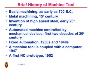
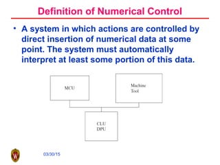
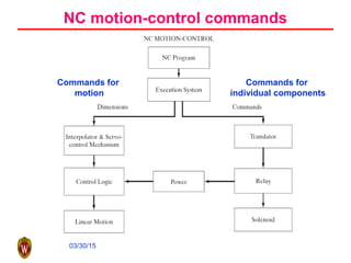
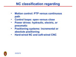
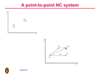
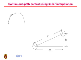
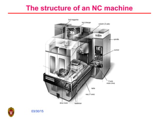
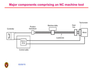
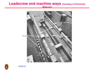
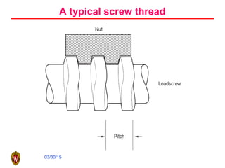
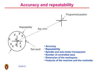
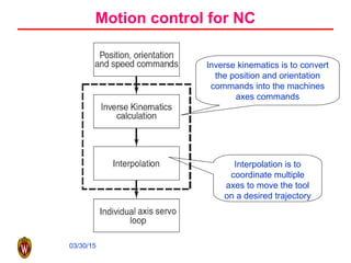
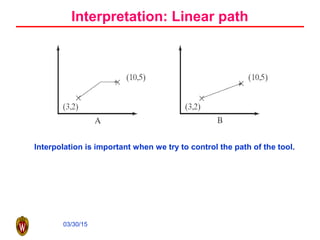
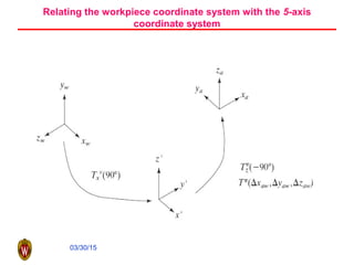
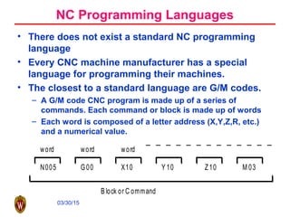
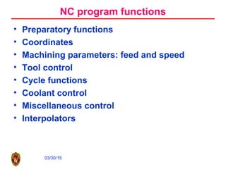
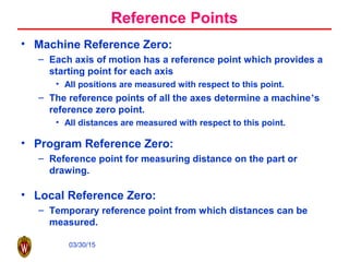
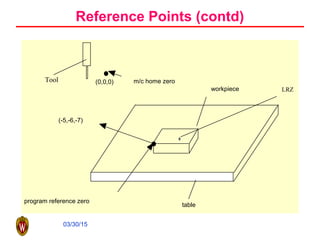
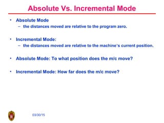
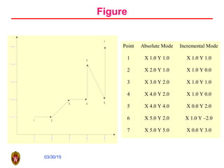
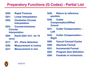
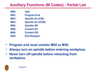
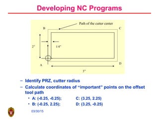
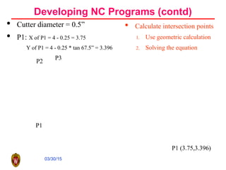
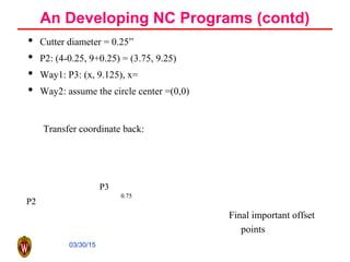
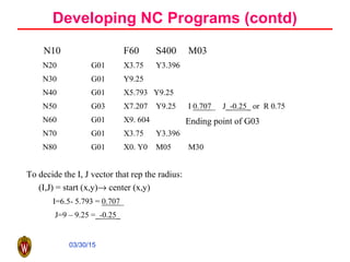
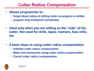
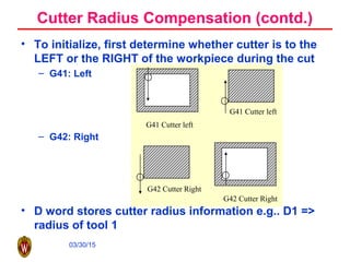
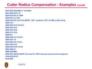
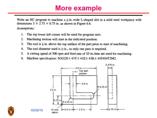
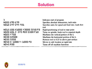
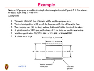
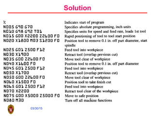
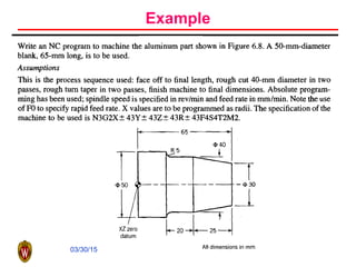
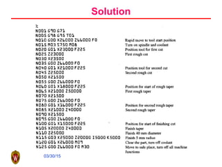
03/30/15
Numerical Control and Programming
03/30/15
An NC system for large parts
03/30/15
Brief History of Machine Tool
• Basic machining, as early as 700 B.C.
• Metal machining, 15th
century
• Invention of high speed steel, early 20th
century
• Automated machine controlled by
mechanical devices, first two decades of 20th
century
• Fixed automation, 1930s and 1940s
• A machine tool is coupled with a computer,
1947
• A first NC prototype, 1952
03/30/15
Definition of Numerical Control
• A system in which actions are controlled by
direct insertion of numerical data at some
point. The system must automatically
interpret at least some portion of this data.
03/30/15
NC motion-control commands
Commands for
individual components
Commands for
motion
03/30/15
NC classification regarding
• Motion control: PTP versus continuous
path
• Control loops: open versus close
• Power drives: hydraulic, electric, or
pneumatic
• Positioning systems: incremental or
absolute positioning
• Hard-wired NC and soft-wired CNC
03/30/15
A point-to-point NC system
03/30/15
Continuous-path control using linear interpolation
03/30/15
The structure of an NC machine
03/30/15
Major components comprising an NC machine tool
03/30/15
Leadscrew and machine ways (Courtesy of Cincinnati
Milacron)
03/30/15
A typical screw thread
03/30/15
Accuracy and repeatability
• Accuracy
• Repeatability
• Spindle and axis-motor horsepower
• Number of controlled axes
• Dimension of the workspace
• Features of the machine and the controller
03/30/15
Motion control for NC
Inverse kinematics is to convert
the position and orientation
commands into the machines
axes commands
Interpolation is to
coordinate multiple
axes to move the tool
on a desired trajectory
03/30/15
Interpretation: Linear path
Interpolation is important when we try to control the path of the tool.
03/30/15
A DDA
03/30/15
Two-axis control
03/30/15
A linear interpolator example
03/30/15
03/30/15
Machine Kinematics: A Cartesian machine
03/30/15
A lathe
03/30/15
A three-axis vertical milling machine
03/30/15
5-axis machine - 1
03/30/15
5-axis machine - 2
03/30/15
5-axis machine - 3
03/30/15
Rotary table attachment
(Courtesy of Fadal Machine)
03/30/15
Five-axis machine coordinate systems
03/30/15
Relating the workpiece coordinate system with the 5-axis
coordinate system
03/30/15
NC Manual Programming
• One needs to tell the controller what needs to be
done in order to machine a particular component.
CNC programs are the means of achieving this.
• CNC programs are made up of a series of commands
or blocks that inform the controller what must be
done, step by step. A CNC program is sequentially
executed, one step at a time and the controller
executes the commands in the same order as
encountered.
• Programming can be done in several ways:
– On line—using the machine’s controller
– Off line—coding and later downloading using tapes, etc.
03/30/15
N005 G00 X10 Y 10 Z10 M 03
word word word
B lock or C ommand
NC Programming Languages
• There does not exist a standard NC programming
language
• Every CNC machine manufacturer has a special
language for programming their machines.
• The closest to a standard language are G/M codes.
– A G/M code CNC program is made up of a series of
commands. Each command or block is made up of words
– Each word is composed of a letter address (X,Y,Z,R, etc.)
and a numerical value.
03/30/15
NC program functions
• Preparatory functions
• Coordinates
• Machining parameters: feed and speed
• Tool control
• Cycle functions
• Coolant control
• Miscellaneous control
• Interpolators
03/30/15
Reference Points
• Machine Reference Zero:
– Each axis of motion has a reference point which provides a
starting point for each axis
• All positions are measured with respect to this point.
– The reference points of all the axes determine a machine’s
reference zero point.
• All distances are measured with respect to this point.
• Program Reference Zero:
– Reference point for measuring distance on the part or
drawing.
• Local Reference Zero:
– Temporary reference point from which distances can be
measured.
03/30/15
Reference Points (contd)
program reference zero
(-5,-6,-7)
workpiece
table
(0,0,0) m/c home zero
LRZ
Tool
03/30/15
Absolute Vs. Incremental Mode
• Absolute Mode
– the distances moved are relative to the program zero.
• Incremental Mode:
– the distances moved are relative to the machine’s current position.
• Absolute Mode: To what position does the m/c move?
• Incremental Mode: How far does the m/c move?
03/30/15
Figure
1
7
6
5
43
2
1 432 5
14325
Point Absolute Mode Incremental Mode
1 X 1.0 Y 1.0 X 1.0 Y 1.0
2 X 2.0 Y 1.0 X 1.0 Y 0.0
3 X 3.0 Y 2.0 X 1.0 Y 1.0
4 X 4.0 Y 2.0 X 1.0 Y 0.0
5 X 4.0 Y 4.0 X 0.0 Y 2.0
6 X 5.0 Y 2.0 X 1.0 Y –2.0
7 X 5.0 Y 5.0 X 0.0 Y 3.0
03/30/15
Machine Configuration
Y
Z
X
Vertical Milling Machine
X
Z
Y
Horizontal Milling Machine
03/30/15
Components of a G/M Code Program
• N: Specifies a sequence number for program command
identification (e.g., N05, N0010, ..., etc.)
• G: Specifies Preparatory Functions which allow various modes
to be set from within the program (e.g., G90-sets absolute
mode, etc.)
• X,Y,Z: Specify linear movement along the axes (e.g., X10 means
move 10 units in the +x direction)
• A,B,C: Specify the rotary motions
• F: Specifies the desired feed rate (e.g., F3.5 means 3.5 distance
units/time unit)
• S: Specifies the spindle speed (usually in rpm) (e.g., S2000
means spindle rotates at 2000 rpm)
• M: Specifies Miscellaneous functions like spindle stop (M05)
03/30/15
• 3-axis Vertical milling machine
In all movements, consider tool tip as moving, NOT the
axes
spindle
cutting tool
table
-X +X
-Z
+z
+Y
-Y
Machine Axes
03/30/15
• Program Reference Zero (PRZ)
• PRZ can be set up manually or within NC program
– Nxx G92 Xxx Yxx Zxx
– e.g. N020 G92 X5.000 Y6.000 Z7.000
==> Location of Home Zero is (5,6,7)
(i.e., the zero point has been shifted)
program reference zero
(-5,-6,-7)
workpiece
table
(0,0,0) m/c home zero
Machine Home Zero
03/30/15
Before Writing Any NC Program
• Develop a sequence of operations.
• Do all math necessary and “mark up” your blueprint.
• Program zero & absolute mode (incremental mode)
• Determine the Tool Motion:
– Rapid motion G00
– St. Line Cutting Motion G01
– Circular Motion G02 CW; G03 CCW Depends on the tool
thread direction.
– All these are MODAL commands
03/30/15
Sample G/M Code
N015 G00 X5.0 Y5.0
– rapid rate
– minimize “air cutting”
– need not be in a straight. line
Tool at
start
position
Program Zero
5.0
5.0
03/30/15
Sample G/M Code
Centerline Movements
– Tool moves along straight line at specified feed rate
– Feed Rate is also a modal command.
– Used for operations like: drilling a hole, milling a straight
surface, milling an angular surface.
Start
End
Program
Zero
5
5
N025G01X5.Y5.F3.5
3.5ipm
03/30/15
Sample G/M Code
Use R. or I, J to specify radius
N015 G03 X5.0 Y5.0 I-2.0J0.0F3.5
03/30/15
Preparatory Functions (G Codes) - Partial List
G00: Rapid Traverse
G01: Linear Interpolation
G02: Clockwise Circular
Interpolation
G03: Counterclockwise
Circular
Interpolation
G04: Dwell (G04 10.0 - for 10
secs)
G17: XY—Plane Selection
G20: Measurement in inches
G21: Measurement in mm.
G28: Return to reference
position
G40: Cutter
Compensation/Offset
Cancel
G41: Cutter Compensation—
Left
G42: Cutter Compensation—
Right
G80: Cancel Canned Cycles
G90: Absolute Format
G91: Incremental Format
G92: Program Zero Definition
G94: Feedrate in inches/min.
03/30/15
Auxiliary Functions (M Codes) - Partial List
M00: Halt
M02: Program End
M03: Spindle On (CW)
M04: Spindle On (CCW)
M05: Spindle Off
M08: Coolant On
M09: Coolant Off
M30: End Newpart
• Program end must contain M02 or M30.
• Always turn on spindle before entering workpiece.
• Never turn off spindle before retracting from
workpiece.
03/30/15
– Identify PRZ, cutter radius
– Calculate coordinates of “important” points on the offset
tool path
• A: (-0.25, -0.25); C: (3.25, 2.25)
• B: (-0.25, 2.25); D: (3.25, -0.25)
Developing NC Programs
D
C
Path of the cutter center
2” 1/4”
3”
B
A
03/30/15
Developing NC Programs (contd)
• Cutter diameter = 0.5”
• P1: X of P1 = 4 - 0.25 = 3.75
Y of P1 = 4 - 0.25 * tan 67.5” = 3.396
• Calculate intersection points
1. Use geometric calculation
2. Solving the equation
P1 (3.75,3.396)
P1
P2
P3
03/30/15
An Developing NC Programs (contd)
• Cutter diameter = 0.25”
• P2: (4-0.25, 9+0.25) = (3.75, 9.25)
• Way1: P3: (x, 9.125), x=
• Way2: assume the circle center =(0,0)
0.75
P3
P2
0.75
P3
P2
Transfer coordinate back:
Final important offset
points
03/30/15
Developing NC Programs (contd)
N10 F60 S400 M03
N20 G01 X3.75 Y3.396
N30 G01 Y9.25
N40 G01 X5.793 Y9.25
N50 G03 X7.207 Y9.25 I 0.707_ J_-0.25_ or R 0.75
N60 G01 X9. 604
N70 G01 X3.75 Y3.396
N80 G01 X0. Y0 M05 M30
To decide the I, J vector that rep the radius:
(I,J) = start (x,y)→ center (x,y)
I=6.5- 5.793 = 0.707_
J=9 – 9.25 =_-0.25_
Ending point of G03
03/30/15
Cutter Radius Compensation
• Allows programmer to:
– forget about radius of milling cutter as program is written
– program only workpiece coordinates
• Used only when you are milling on the “side” of the
cutter. Not used for drills, tapes, reamers, face mills,
etc.
• 3 basic steps to using cutter radius compensation
– Initialize cutter radius compensation
– Make tool movements using cutter radius compensation
– Cancel cutter radius compensation
03/30/15
• To initialize, first determine whether cutter is to the
LEFT or the RIGHT of the workpiece during the cut
– G41: Left
– G42: Right
• D word stores cutter radius information e.g.. D1 =>
radius of tool 1
G42 Cutter Right
G42 Cutter Right
G41 Cutter left
G41 Cutter left
Cutter Radius Compensation (contd.)
03/30/15
Cutter Radius Compensation (contd.)
Tool Position prior to initialization:
• Position the tool so that as we instate cutter radius
compensation, and begin cutting, a right angle is
formed.
– G41, G42 are modal commands canceled using G40.
• Get tool out of workpiece before canceling cutter
radius compensation.
• G43 for tool length compensation
• H word H1: length of tool 1.
• Now let’s try to put it all together and look at a full
example of cutter radius compensation.
03/30/15
Cutter Radius Compensation - Examples
4.00
6.00
1” Radius (typ)
0.5 Wall (typ)
φ 1” cutter
2.00
1.50
0.50
03/30/15
Cutter Radius Compensation - Examples (contd)
N005 G92 X10. Y10. Z10 (Set up program zero; just example numbers)
N010 G90 S400 M03 (Select absolute mode and turn the spindle on CLW at 400 RPM)
N015 G00 X1.5 Y2. (Move over to first X Y position, still tool centerline coordinates.)
N020 G43 N01 Z.1 M06 (Instate tool length compensation, move tool down, and turn
on the coolant)
N025 G01 Z-.5 F6.5 (Plunge tool into work surface at 6.5 IPM)
N030 G42 D31 X.5 F3.0 (Instate cutter radius compensation.)
N035 Y2.5
N040 G02 X1.5 Y3.5 R1.
N045 G01 X4.5
N050 G02 X5.5 Y2.5 R1.
N055 G01 Y1.5.
N060 G02 X4.5 Y.5 R1.
N065 G01 X1.5
N070 G02 X.5 Y1.5 R1.
N075 G01 Y2.0 (Last cutting move back to Y2.0)
N080 G00 Z.1 (Move tool up to clear workpiece in Z)
N085 G40 M09 (Cancel cutter radius compensation and turn off coolant)
N090 G91 G28 X0 Y0 Z0 (Send the machine to home position)
N095 M30 (End of program)
03/30/15
Cutter Radius Compensation - Examples (contd)
2 .0
3.0
4 . 0
2.6
0 .2
1 .0 1 . 0
R 0 . 4
0 .2
0.20.2
1.0
0.2
P r o g r a m Z e r o
03/30/15
Cutter Radius Compensation - Examples (contd)
N010 G90 S305 M03 (1” End Mill)
N015 G00 X4.6 Y-.6
N020 G43 H01 Z.1 M08
N025 G01 Z.-2 F30.
N030 G42 D31 X3.8 F4.0 (NOTE: “D31” would be “H31” for 0M or 3M control)
N035 Y2.4
N040 G03 X3.4 Y2.8 R.4
N045 G01 X3.0
N050 X2.0 Y2.6
N055 X1.0 Y2.8
N058 X.6
N060 G03 X.2 Y2.4 R.4
N065 G01 Y.6
N070 G03 X.6 Y.2 R.4
N075 G01 X3.4
N080 G03 X3.8 Y.6 R.4
N085 G00 Z.1
N090 G40 M09
N095 G91 G28 Z0 (NOTE: No need for “M19” because only one tool in program)
N100 G28 X0 Y0
N105 M30
03/30/15
More example
03/30/15
Solution
03/30/15
Example
03/30/15
Solution
03/30/15
Example
03/30/15
Solution

NC pogramming

  • 1.
  • 2.
    03/30/15 An NC systemfor large parts
  • 3.
    03/30/15 Brief History ofMachine Tool • Basic machining, as early as 700 B.C. • Metal machining, 15th century • Invention of high speed steel, early 20th century • Automated machine controlled by mechanical devices, first two decades of 20th century • Fixed automation, 1930s and 1940s • A machine tool is coupled with a computer, 1947 • A first NC prototype, 1952
  • 4.
    03/30/15 Definition of NumericalControl • A system in which actions are controlled by direct insertion of numerical data at some point. The system must automatically interpret at least some portion of this data.
  • 5.
    03/30/15 NC motion-control commands Commandsfor individual components Commands for motion
  • 6.
    03/30/15 NC classification regarding •Motion control: PTP versus continuous path • Control loops: open versus close • Power drives: hydraulic, electric, or pneumatic • Positioning systems: incremental or absolute positioning • Hard-wired NC and soft-wired CNC
  • 7.
  • 8.
  • 9.
  • 10.
  • 11.
    03/30/15 Leadscrew and machineways (Courtesy of Cincinnati Milacron)
  • 12.
  • 13.
    03/30/15 Accuracy and repeatability •Accuracy • Repeatability • Spindle and axis-motor horsepower • Number of controlled axes • Dimension of the workspace • Features of the machine and the controller
  • 14.
    03/30/15 Motion control forNC Inverse kinematics is to convert the position and orientation commands into the machines axes commands Interpolation is to coordinate multiple axes to move the tool on a desired trajectory
  • 15.
    03/30/15 Interpretation: Linear path Interpolationis important when we try to control the path of the tool.
  • 16.
  • 17.
  • 18.
  • 19.
  • 20.
  • 21.
  • 22.
  • 23.
  • 24.
  • 25.
  • 26.
  • 27.
  • 28.
    03/30/15 Relating the workpiececoordinate system with the 5-axis coordinate system
  • 29.
    03/30/15 NC Manual Programming •One needs to tell the controller what needs to be done in order to machine a particular component. CNC programs are the means of achieving this. • CNC programs are made up of a series of commands or blocks that inform the controller what must be done, step by step. A CNC program is sequentially executed, one step at a time and the controller executes the commands in the same order as encountered. • Programming can be done in several ways: – On line—using the machine’s controller – Off line—coding and later downloading using tapes, etc.
  • 30.
    03/30/15 N005 G00 X10Y 10 Z10 M 03 word word word B lock or C ommand NC Programming Languages • There does not exist a standard NC programming language • Every CNC machine manufacturer has a special language for programming their machines. • The closest to a standard language are G/M codes. – A G/M code CNC program is made up of a series of commands. Each command or block is made up of words – Each word is composed of a letter address (X,Y,Z,R, etc.) and a numerical value.
  • 31.
    03/30/15 NC program functions •Preparatory functions • Coordinates • Machining parameters: feed and speed • Tool control • Cycle functions • Coolant control • Miscellaneous control • Interpolators
  • 32.
    03/30/15 Reference Points • MachineReference Zero: – Each axis of motion has a reference point which provides a starting point for each axis • All positions are measured with respect to this point. – The reference points of all the axes determine a machine’s reference zero point. • All distances are measured with respect to this point. • Program Reference Zero: – Reference point for measuring distance on the part or drawing. • Local Reference Zero: – Temporary reference point from which distances can be measured.
  • 33.
    03/30/15 Reference Points (contd) programreference zero (-5,-6,-7) workpiece table (0,0,0) m/c home zero LRZ Tool
  • 34.
    03/30/15 Absolute Vs. IncrementalMode • Absolute Mode – the distances moved are relative to the program zero. • Incremental Mode: – the distances moved are relative to the machine’s current position. • Absolute Mode: To what position does the m/c move? • Incremental Mode: How far does the m/c move?
  • 35.
    03/30/15 Figure 1 7 6 5 43 2 1 432 5 14325 PointAbsolute Mode Incremental Mode 1 X 1.0 Y 1.0 X 1.0 Y 1.0 2 X 2.0 Y 1.0 X 1.0 Y 0.0 3 X 3.0 Y 2.0 X 1.0 Y 1.0 4 X 4.0 Y 2.0 X 1.0 Y 0.0 5 X 4.0 Y 4.0 X 0.0 Y 2.0 6 X 5.0 Y 2.0 X 1.0 Y –2.0 7 X 5.0 Y 5.0 X 0.0 Y 3.0
  • 36.
    03/30/15 Machine Configuration Y Z X Vertical MillingMachine X Z Y Horizontal Milling Machine
  • 37.
    03/30/15 Components of aG/M Code Program • N: Specifies a sequence number for program command identification (e.g., N05, N0010, ..., etc.) • G: Specifies Preparatory Functions which allow various modes to be set from within the program (e.g., G90-sets absolute mode, etc.) • X,Y,Z: Specify linear movement along the axes (e.g., X10 means move 10 units in the +x direction) • A,B,C: Specify the rotary motions • F: Specifies the desired feed rate (e.g., F3.5 means 3.5 distance units/time unit) • S: Specifies the spindle speed (usually in rpm) (e.g., S2000 means spindle rotates at 2000 rpm) • M: Specifies Miscellaneous functions like spindle stop (M05)
  • 38.
    03/30/15 • 3-axis Verticalmilling machine In all movements, consider tool tip as moving, NOT the axes spindle cutting tool table -X +X -Z +z +Y -Y Machine Axes
  • 39.
    03/30/15 • Program ReferenceZero (PRZ) • PRZ can be set up manually or within NC program – Nxx G92 Xxx Yxx Zxx – e.g. N020 G92 X5.000 Y6.000 Z7.000 ==> Location of Home Zero is (5,6,7) (i.e., the zero point has been shifted) program reference zero (-5,-6,-7) workpiece table (0,0,0) m/c home zero Machine Home Zero
  • 40.
    03/30/15 Before Writing AnyNC Program • Develop a sequence of operations. • Do all math necessary and “mark up” your blueprint. • Program zero & absolute mode (incremental mode) • Determine the Tool Motion: – Rapid motion G00 – St. Line Cutting Motion G01 – Circular Motion G02 CW; G03 CCW Depends on the tool thread direction. – All these are MODAL commands
  • 41.
    03/30/15 Sample G/M Code N015G00 X5.0 Y5.0 – rapid rate – minimize “air cutting” – need not be in a straight. line Tool at start position Program Zero 5.0 5.0
  • 42.
    03/30/15 Sample G/M Code CenterlineMovements – Tool moves along straight line at specified feed rate – Feed Rate is also a modal command. – Used for operations like: drilling a hole, milling a straight surface, milling an angular surface. Start End Program Zero 5 5 N025G01X5.Y5.F3.5 3.5ipm
  • 43.
    03/30/15 Sample G/M Code UseR. or I, J to specify radius N015 G03 X5.0 Y5.0 I-2.0J0.0F3.5
  • 44.
    03/30/15 Preparatory Functions (GCodes) - Partial List G00: Rapid Traverse G01: Linear Interpolation G02: Clockwise Circular Interpolation G03: Counterclockwise Circular Interpolation G04: Dwell (G04 10.0 - for 10 secs) G17: XY—Plane Selection G20: Measurement in inches G21: Measurement in mm. G28: Return to reference position G40: Cutter Compensation/Offset Cancel G41: Cutter Compensation— Left G42: Cutter Compensation— Right G80: Cancel Canned Cycles G90: Absolute Format G91: Incremental Format G92: Program Zero Definition G94: Feedrate in inches/min.
  • 45.
    03/30/15 Auxiliary Functions (MCodes) - Partial List M00: Halt M02: Program End M03: Spindle On (CW) M04: Spindle On (CCW) M05: Spindle Off M08: Coolant On M09: Coolant Off M30: End Newpart • Program end must contain M02 or M30. • Always turn on spindle before entering workpiece. • Never turn off spindle before retracting from workpiece.
  • 46.
    03/30/15 – Identify PRZ,cutter radius – Calculate coordinates of “important” points on the offset tool path • A: (-0.25, -0.25); C: (3.25, 2.25) • B: (-0.25, 2.25); D: (3.25, -0.25) Developing NC Programs D C Path of the cutter center 2” 1/4” 3” B A
  • 47.
    03/30/15 Developing NC Programs(contd) • Cutter diameter = 0.5” • P1: X of P1 = 4 - 0.25 = 3.75 Y of P1 = 4 - 0.25 * tan 67.5” = 3.396 • Calculate intersection points 1. Use geometric calculation 2. Solving the equation P1 (3.75,3.396) P1 P2 P3
  • 48.
    03/30/15 An Developing NCPrograms (contd) • Cutter diameter = 0.25” • P2: (4-0.25, 9+0.25) = (3.75, 9.25) • Way1: P3: (x, 9.125), x= • Way2: assume the circle center =(0,0) 0.75 P3 P2 0.75 P3 P2 Transfer coordinate back: Final important offset points
  • 49.
    03/30/15 Developing NC Programs(contd) N10 F60 S400 M03 N20 G01 X3.75 Y3.396 N30 G01 Y9.25 N40 G01 X5.793 Y9.25 N50 G03 X7.207 Y9.25 I 0.707_ J_-0.25_ or R 0.75 N60 G01 X9. 604 N70 G01 X3.75 Y3.396 N80 G01 X0. Y0 M05 M30 To decide the I, J vector that rep the radius: (I,J) = start (x,y)→ center (x,y) I=6.5- 5.793 = 0.707_ J=9 – 9.25 =_-0.25_ Ending point of G03
  • 50.
    03/30/15 Cutter Radius Compensation •Allows programmer to: – forget about radius of milling cutter as program is written – program only workpiece coordinates • Used only when you are milling on the “side” of the cutter. Not used for drills, tapes, reamers, face mills, etc. • 3 basic steps to using cutter radius compensation – Initialize cutter radius compensation – Make tool movements using cutter radius compensation – Cancel cutter radius compensation
  • 51.
    03/30/15 • To initialize,first determine whether cutter is to the LEFT or the RIGHT of the workpiece during the cut – G41: Left – G42: Right • D word stores cutter radius information e.g.. D1 => radius of tool 1 G42 Cutter Right G42 Cutter Right G41 Cutter left G41 Cutter left Cutter Radius Compensation (contd.)
  • 52.
    03/30/15 Cutter Radius Compensation(contd.) Tool Position prior to initialization: • Position the tool so that as we instate cutter radius compensation, and begin cutting, a right angle is formed. – G41, G42 are modal commands canceled using G40. • Get tool out of workpiece before canceling cutter radius compensation. • G43 for tool length compensation • H word H1: length of tool 1. • Now let’s try to put it all together and look at a full example of cutter radius compensation.
  • 53.
    03/30/15 Cutter Radius Compensation- Examples 4.00 6.00 1” Radius (typ) 0.5 Wall (typ) φ 1” cutter 2.00 1.50 0.50
  • 54.
    03/30/15 Cutter Radius Compensation- Examples (contd) N005 G92 X10. Y10. Z10 (Set up program zero; just example numbers) N010 G90 S400 M03 (Select absolute mode and turn the spindle on CLW at 400 RPM) N015 G00 X1.5 Y2. (Move over to first X Y position, still tool centerline coordinates.) N020 G43 N01 Z.1 M06 (Instate tool length compensation, move tool down, and turn on the coolant) N025 G01 Z-.5 F6.5 (Plunge tool into work surface at 6.5 IPM) N030 G42 D31 X.5 F3.0 (Instate cutter radius compensation.) N035 Y2.5 N040 G02 X1.5 Y3.5 R1. N045 G01 X4.5 N050 G02 X5.5 Y2.5 R1. N055 G01 Y1.5. N060 G02 X4.5 Y.5 R1. N065 G01 X1.5 N070 G02 X.5 Y1.5 R1. N075 G01 Y2.0 (Last cutting move back to Y2.0) N080 G00 Z.1 (Move tool up to clear workpiece in Z) N085 G40 M09 (Cancel cutter radius compensation and turn off coolant) N090 G91 G28 X0 Y0 Z0 (Send the machine to home position) N095 M30 (End of program)
  • 55.
    03/30/15 Cutter Radius Compensation- Examples (contd) 2 .0 3.0 4 . 0 2.6 0 .2 1 .0 1 . 0 R 0 . 4 0 .2 0.20.2 1.0 0.2 P r o g r a m Z e r o
  • 56.
    03/30/15 Cutter Radius Compensation- Examples (contd) N010 G90 S305 M03 (1” End Mill) N015 G00 X4.6 Y-.6 N020 G43 H01 Z.1 M08 N025 G01 Z.-2 F30. N030 G42 D31 X3.8 F4.0 (NOTE: “D31” would be “H31” for 0M or 3M control) N035 Y2.4 N040 G03 X3.4 Y2.8 R.4 N045 G01 X3.0 N050 X2.0 Y2.6 N055 X1.0 Y2.8 N058 X.6 N060 G03 X.2 Y2.4 R.4 N065 G01 Y.6 N070 G03 X.6 Y.2 R.4 N075 G01 X3.4 N080 G03 X3.8 Y.6 R.4 N085 G00 Z.1 N090 G40 M09 N095 G91 G28 Z0 (NOTE: No need for “M19” because only one tool in program) N100 G28 X0 Y0 N105 M30
  • 57.
  • 58.
  • 59.
  • 60.
  • 61.
  • 62.