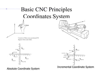
SlideShare a Scribd company logo
1 of 91
Motivation and uses
To manufacture complex curved geometries in 2D or 3D
was extremely expensive by mechanical means (which
usually would require complex jigs to control the cutter
motions)
Machining components with repeatable accuracy
Unmanned machining operations
Advantages of CNC
- Easier to program;
- Easy storage of existing programs;
- Easy to change a program
- Avoids human errors
- safer to operate
- Complex geometry is produced as cheaply as simple ones
- Usually generates closer tolerances than manual machines
Vertical Milling machine architecture
Conventional milling machines
Types of CNC machines
Based on Motion Type:
Point-to-Point or Continuous path
Based on Control Loops:
Open loop or Closed loop
Based on Power Supply:
Electric or Hydraulic or Pneumatic
Based on Positioning System
Incremental or Absolute
Basic CNC Principles
• Using a vertical mill
machining center as an
example, there are typically
three linear axes of motion.
Each is given an alphabetic
designation or address. The
machine table motion side
to side is called the “X”
axis. Table movement in
and out is the “Y” axis,
while head movement up
and down the column is the
“Z” axis.
Basic CNC Principles
Coordinates System
Absolute Coordinate System
Incremental Coordinate System
Basic CNC Principles
All computer controlled machines are able to accurately and
repeatedly control motion in various directions. Each of these
directions of motion is called an axis. Depending on the machine type
there are commonly two to five axes.
Additionally, a CNC axis may be either a linear axis in which movement
is in a straight line, or a rotary axis with motion following a circular
path.
Basic CNC Principles
If a rotary table is added to the machine table, then
the fourth axis is designated the “b” axis.
How CNC Works
• Controlled by G and M codes.
• These are number values and co-ordinates.
• Each number or code is assigned to a particular
operation.
• Typed in manually to CAD by machine
operators.
• G&M codes are automatically generated by the
computer software.
Features of CNC Machinery
• The tool or material moves.
• Tools can operate in 1-5 axes.
• Larger machines have a machine control unit
(MCU) which manages operations.
• Movement is controlled by a motors
(actuators).
• Feedback is provided by sensors (transducers)
• Tool magazines are used to change tools
automatically.
Tools
• Most are made from
high speed steel (HSS),
tungsten carbide or ceramics.
• Tools are designed to direct waste away from
the material.
• Some tools need coolant such as oil to protect
the tool and work.
Tool Paths, Cutting
and Plotting Motions
• Tool paths describes the route the cutting tool takes.
• Motion can be described as point to point, straight cutting or
contouring.
• Speeds are the rate at which the tool operates e.g. rpm.
• Feeds are the rate at which the cutting tool and work piece
move in relation to each other.
• Feeds and speeds are determined by cutting depth, material
and quality of finish needed. e.g. harder materials need slower
feeds and speeds.
• Rouging cuts remove larger amounts of material than finishing
cuts.
• Rapid traversing allows the tool or work piece to move rapidly
when no machining is taking place.
Manual NC programming
Part program: A computer program to specify
- Which tool should be loaded on the machine spindle;
- What are the cutting conditions (speed, feed, coolant ON/OFF etc)
- The start point and end point of a motion segment
- how to move the tool with respect to the machine.
Standard Part programming language: RS 274-D (Gerber, GN-code)
History of CNC
The RS274-D is a word address format
Each line of program == 1 block
Each block is composed of several instructions, or (words)
Sequence and format of words:
N3 G2 X+1.4 Y+1.4 Z+1.4 I1.4 J1.4 K1.4 F3.2 S4 T4 M2
sequence no
preparatory function
destination coordinates dist to center of circle
feed rate spindle speed
tool
Other function
Manual Part Programming Example
Tool size = 0.25 inch,
Feed rate = 6 inch per minute,
Cutting speed = 300 rpm,
Tool start position: 2.0, 2.0
Programming in inches
(4, 4)
(2, 2)
5”
p0
p1
p2
5”
2.5”
1”
45°
p3
p4
p5
Motion of tool:
p0  p1  p2  p3  p4  p5  p1  p0
Spindle CCW
(4, 4)
(2, 2)
5”
p0
p1
p2
5”
2.5”
1”
45°
p3
p4
p5
1. Set up the programming parameters
N010 G70 G90 G94 G97 M04
Programming in inches
Use absolute coordinates
Spindle speed in rpm
Feed in ipm
Flood coolant ON
(4, 4)
(2, 2)
5”
p0
p1
p2
5”
2.5”
1”
45°
p3
p4
p5
2. Set up the machining conditions
N020 G17 G75 F6.0 S300 T1001 M08
Machine moves in XY-plane
Feed rate
Tool no.
Spindle speed
Use full-circle interpolation
(4, 4)
(2, 2)
5”
p0
p1
p2
5”
2.5”
1”
45°
p3
p4
p5
3. Move tool from p0 to p1 in straight line
N030 G01 X3.875 Y3.698
Linear interpolation
target coordinates
(4, 4)
(2, 2)
5”
p0
p1
p2
5”
2.5”
1”
45°
p3
p4
p5
4. Cut profile from p1 to p2
N040 G01 X3.875 Y9.125
Linear interpolation
target coordinates
N040 G01 Y9.125
X-coordinate does not change  no need to program it
or
(4, 4)
(2, 2)
5”
p0
p1
p2
5”
2.5”
1”
45°
p3
p4
p5
5. Cut profile from p2 to p3
N050 G01 X5.634 Y9.125
Linear interpolation
target coordinates
1”
p3
.125
(x, y)
(6.5, 9)
y = 9 + 0.125 = 9.125
(6.5 - x)2 + 0.1252 = (1 - 0.125)2
x = 5.634
coordinates of center of circle
(4, 4)
(2, 2)
5”
p0
p1
p2
5”
2.5”
1”
45°
p3
p4
p5
6. Cut along circle from p3 to p4
N060 G03 X7.366 Y9.125 I6.5 J9.0
circular interpolation, CCW motion
target coordinates
(4, 4)
(2, 2)
5”
p0
p1
p2
5”
2.5”
1”
45°
p3
p4
p5
7. Cut from p4 to p5
N070 G01 X9.302
target coordinates (Y is unchanged)
Linear interpolation
(4, 4)
(2, 2)
5”
p0
p1
p2
5”
2.5”
1”
45°
p3
p4
p5
8. Cut from p5 to p1
N080 G01 X3.875 Y3.698
target coordinates (see step 3)
Linear interpolation
(4, 4)
(2, 2)
5”
p0
p1
p2
5”
2.5”
1”
45°
p3
p4
p5
9. Return to home position, stop program
N090 G01 X2.0 Y2.0 M30
end of data
target coordinates (see step 3)
Linear interpolation
N100 M00
program stop
CNC Programming Basics
• CNC instructions are called part program commands.
• When running, a part program is interpreted one command line
at a time until all lines are completed.
• Commands, which are also referred to as blocks, are made up
of words which each begin with a letter address and end with a
numerical value.
CNC Programming Basics
• Each letter address relates to a specific machine function. “G”
and “M” letter addresses are two of the most common. A “G”
letter specifies certain machine preparations such as inch or
metric modes, or absolutes versus incremental modes.
• A “M” letter specifies miscellaneous machine functions and
work like on/off switches for coolant flow, tool changing, or
spindle rotation. Other letter addresses are used to direct a
wide variety of other machine commands.
CNC programming
Important things to know:
• Coordinate System
• Units, incremental or absolute positioning
• Coordinates: X,Y,Z, RX,RY,RZ
• Feed rate and spindle speed
• Coolant Control: On/Off, Flood, Mist
• Tool Control: Tool and tool parameters
• Programming consists of a series of instructions in form of letter codes
• Preparatory Codes:
• G codes- Initial machining setup and establishing operating conditions
• N codes- specify program line number to executed by the MCU
• Axis Codes: X,Y,Z - Used to specify motion of the slide along X, Y, Z
direction
• Feed and Speed Codes: F and S- Specify feed and spindle speed
• Tool codes: T – specify tool number
• Miscellaneous codes – M codes For coolant control and other activities
CNC programming
Programming Key Letters
• O - Program number (Used for program identification)
• N - Sequence number (Used for line identification)
• G - Preparatory function
• X - X axis designation
• Y - Y axis designation
• Z - Z axis designation
• R - Radius designation
• F – Feed rate designation
• S - Spindle speed designation
• H - Tool length offset designation
• D - Tool radius offset designation
• T - Tool Designation
• M - Miscellaneous function
Explanation of commonly used G
codes
• G00 – Preparatory code to control final position of the tool and
not concerned with the path that is followed in arriving at the
final destination.
• G01 – Tool is required to move in a straight line connecting
current position and final position. Used for tool movement
without any machining- point to point control. (linear
interpolation)
• G02 – Tool path followed is along an arc specified by I, J and
K codes.( circular interpolation)
Table of Important G codes
G00 Rapid Transverse
G01 Linear Interpolation
G02 Circular Interpolation, CW
G03 Circular Interpolation, CCW
G17 XY Plane,G18 XZ Plane,G19 YZ Plane
G20/G70 Inch units
G21/G71 Metric Units
G40 Cutter compensation cancel
G41 Cutter compensation left
G42 Cutter compensation right
G43 Tool length compensation (plus)
G44 Tool length compensation (minus)
G49 Tool length compensation cancel
G80 Cancel canned cycles
G81 Drilling cycle
G82 Counter boring cycle
G83 Deep hole drilling cycle
Table of Important M codes
• M00 Program stop
• M01 Optional program stop
• M02 Program end
• M03 Spindle on clockwise
• M04 Spindle on counterclockwise
• M05 Spindle stop
• M06 Tool change
• M08 Coolant on
• M09 Coolant off
• M10 Clamps on
• M11 Clamps off
• M30 Program stop, reset to start
Optimum machine programming requires consideration of certain
machine operating parameters including:
• Positioning control
• Compensations
• Special machine features
Positioning control is the ability to program tool and machine slide
movement simultaneously along two or more axes. Positioning may be
for point-to-point movement or for contouring movement along a
continuous path. Contouring requires tool movement along multiple axes
simultaneously. This movement is referred to as “Interpolation” which is
the process of calculating intermediate values between specific points
along a programmed path and outputting those values as a precise
motion. Interpolation may be linear having just a start and end point
along a straight line, or circular which requires an end point, a center and
a direction around the arc.
Program Command Parameters
Rules for programming
Block Format
N135 G01 X1.0 Y1.0 Z0.125 F5
Sample Block
• Restrictions on CNC blocks
• Each may contain only one tool move
• Each may contain any number of non-tool move G-codes
• Each may contain only one feed rate
• Each may contain only one specified tool or spindle speed
• The block numbers should be sequential
• Both the program start flag and the program number must be
independent of all other commands (on separate lines)
• The data within a block should follow the sequence shown
in the above sample block
APT Programming Example
Cylindrical Part
F
25
F
22.5
F
17.5
20
Raw Material
Finished Part
70
30
APT Programming Example (Cylindrical Part)
O0013
N0005 G53
N0010 T0303
N0020 G57 G00 X26.00 Z0.0 S500 M04
N0030 G01 X-0.20 F100
N0040 G00 Z2.0
N0050 X50.0 Z50.0
N0060 T0404
N0070 G57 G00 X22.50 Z2.0 S500
N0080 G01 Z-30.0 F100
N0090 G00 X23.0 Z2.0 S500
N0100 G84 X17.5 Z-20.0 D0=200 D2=200 D3=650
N0110 G00 Z2.0
N0120 X50.0 Z50.0
N0130 M30
APT Program Interpretation
O0013
Program identification number
APT Program Interpretation
O0013
N0005 G53
To cancel any previous working zero point
APT Program Interpretation
O0013
N0005 G53
N0010 T0303
N0010 Sequence number
T0303 Select tool number 303
O0013
N0005 G53
N0010 T0404
N0020 G57 G00 X26.0 Z0.0 S500 M04
G57 To set the working zero point as saved
G00 Rapid movement (no cutting)
X26.0 X location (as a diameter; 13 form zero)
Z0.0 Z location
S500 Spindle speed is 500 rpm
M04 Rotate spindle counterclockwise
APT Program Interpretation
x
z
(0,0) +ve
+ve
O0013
N0005 G53
N0010 T0404
N0020 G57 G00 X26.00 Z0.0 S500 M04
N0030 G01 X-0.20 F100
G01 Linear interpolation (cutting)
X-0.20 Move only in x direction until you pass
the center by 0.1 mm (facing)
F100 Set feed rate to 100 mm/min.
APT Program Interpretation
O0013
N0005 G53
N0010 T0404
N0020 G57 G00 X26.00 Z0.0 S500 M04
N0030 G01 X-0.20 F100
N0040 G00 Z2.0
G00 Move rapidly away from work piece (no cutting)
Z2.0 the movement is 2 mm away from the face.
APT Program Interpretation
O0013
N0005 G53
N0010 T0404
N0020 G57 G00 X26.00 Z0.0 S500 M04
N0030 G01 X-0.20 F100
N0040 G00 Z2.0
N0050 X50.0 Z50.0
Go to a safe location away from the
workpiece [x = 50 (25 from zero), z = 50] to
change the tool.
APT Program Interpretation
O0013
N0005 G53
N0010 T0404
N0020 G57 G00 X26.00 Z0.0 S500 M04
N0030 G01 X-0.20 F100
N0040 G00 Z2.0
N0050 X50.0 Z50.0
N0060 T0404
T0404 Select tool number 404
APT Program Interpretation
O0013
N0005 G53
N0010 T0404
N0020 G57 G00 X26.00 Z0.0 S500 M04
N0030 G01 X-0.20 F100
N0040 G00 Z2.0
N0050 X50.0 Z50.0
N0060 T0404
N0070 G57 G00 X22.50 Z2.0 S500
G57 PS0
G00 Rapid movement (no cutting)
X22.50 X location (as a diameter; 11.25 form zero)
Z2.0 Z location
S500 Spindle speed is 500 rpm
APT Program Interpretation
O0013
N0005 G53
N0010 T0404
N0020 G57 G00 X26.00 Z0.0 S500 M04
N0030 G01 X-0.20 F100
N0040 G00 Z2.0
N0050 X50.0 Z50.0
N0060 T0404
N0070 G57 G00 X25.00 Z2.0 S500 M04
N0080 G01 Z-30.0 F100
G01 Linear interpolation (cutting)
Z-30 Move only in z direction (external turning)
F100 Set feed rate to 100 mm/min.
APT Program Interpretation
O0013
N0005 G53
N0010 T0404
N0020 G57 G00 X26.00 Z0.0 S500 M04
N0030 G01 X-0.20 F100
N0040 G00 Z2.0
N0050 X50.0 Z50.0
N0060 T0404
N0070 G57 G00 X25.00 Z2.0 S500 M04
N0080 G01 X22.5 Z-70.0 F100
N0090 G00 X23.0 Z2.0 S500
G00 Move rapidly away from work piece (no cutting) to
location x= 23.0 (11.50 from zero) and z = 2.0.
APT Program Interpretation
O0013
N0005 G53
N0010 T0404
N0020 G57 G00 X26.00 Z0.0 S500 M04
N0030 G01 X-0.20 F100
N0040 G00 Z2.0
N0050 X50.0 Z50.0
N0060 T0404
N0070 G57 G00 X25.00 Z2.0 S500 M04
N0080 G01 X22.5 Z-70.0 F100
N0090 G00 X26.0 Z2.0 S500
N0100 G84 X17.5 Z-20.0 D0=200 D2=200 D3=650
G84 Turning cycle for machining the step
X17.5 final diameter
Z-20 length of step is 20 mm
D0=200 Finish allowance in X direction (0.2 mm) D2=200 Finish
allowance in Z direction (0.2 mm)
D3=650 Depth of cut in each pass (0.65 mm)
APT Program Interpretation
O0013
N0005 G53
N0010 T0404
N0020 G57 G00 X26.00 Z0.0 S500 M04
N0030 G01 X-0.20 F100
N0040 G00 Z2.0
N0050 X50.0 Z50.0
N0060 T0404
N0070 G57 G00 X25.00 Z2.0 S500 M04
N0080 G01 X22.5 Z-70.0 F100
N0090 G00 X26.0 Z2.0 S500
N0100 G84 X17.5 Z-20.0 D0=200 D2=200 D3=650
N0110 G00 Z2.0
G00 Move rapidly away from workpiece (no cutting)
Z2.0 the movement is 2 mm away from the face.
APT Program Interpretation
O0013
N0005 G53
N0010 T0404
N0020 G57 G00 X26.00 Z0.0 S500 M04
N0030 G01 X-0.20 F100
N0040 G00 Z2.0
N0050 X50.0 Z50.0
N0060 T0404
N0070 G57 G00 X25.00 Z2.0 S500 M04
N0080 G01 X22.5 Z-70.0 F100
N0090 G00 X26.0 Z2.0 S500
N0100 G84 X17.5 Z-20.0 D0=200 D2=200 D3=650
N0110 G00 Z2.0
N0120 X50.0 Z50.0
X50.0 Z50.0 Move to the tool changing location
APT Program Interpretation
O0013
N0005 G53
N0010 T0404
N0020 G57 G00 X26.00 Z0.0 S500 M04
N0030 G01 X-0.20 F100
N0040 G00 Z2.0
N0050 X50.0 Z50.0
N0060 T0404
N0070 G57 G00 X25.00 Z2.0 S500 M04
N0080 G01 X22.5 Z-70.0 F100
N0090 G00 X26.0 Z2.0 S500
N0100 G84 X17.5 Z-20.0 D0=200 D2=200 D3=650
N0110 G00 Z2.0
N0120 X50.0 Z50.0 T00
N0130 M30
M30 Program End
APT Program Interpretation
Programming Example
Raw Material Finished Part
Programming Example
G55 X200 Y80
Program 1
N001 M06 T1
N002 M03 rpm 400
N003 G01 X-8 Y0 Z0 XYFeed 150
N004 G01 X-8 Y0 Z-0.5 ZFeed 150
N005 G01 X70 Y0 Z-0.5 XYFeed 75
N006 G01 X70 Y60 Z-0.5 XYFeed 75
N007 G01 X30 Y60 Z-0.5 XYFeed 75
N008 G01 X0 Y40 Z-0.5 XYFeed 75
N009 G01 X0 Y0 Z-0.5 XYFeed 75
N010 G81 R3 E9 N7 Z-0.5
N011 M05
N012 M02
x
y
Programming Example
Tool Change
G55 X200 Y80
Program 2
N001 M06 T2
N002 M03 rpm 400
N003 G01 X-8 Y0 Z0 XYFeed 150
N004 G01 X20 Y15 Z10 XYFeed 150 ZFeed 150
N005 G01 X20 Y15 Z-10 ZFeed 75
N006 G01 X20 Y15 Z10 ZFeed 150
N007 G01 X50 Y15 Z10 ZFeed 150
N008 G01 X50 Y15 Z-10 ZFeed 75
N009 G01 X50 Y15 Z10 ZFeed 150
N010 G01 X50 Y45 Z10 ZFeed 150
N011 G01 X50 Y45 Z-10 ZFeed 75
N012 G01 X50 Y45 Z10 ZFeed 150
N013 M05
N014 M02
x
y
Program Interpretation
G55 X200 Y80
Setting the datum to the lower left corner of the work piece
Program Interpretation
G55 X200 Y80
Program 1
Program Identification Number
Program Interpretation
G55 X200 Y80
Program 1
N001 M06 T1
N001 Sequence Number
M06 Tool Change (End Mill with
Diameter=12mm
T1 Tool Number
Program Interpretation
G55 X200 Y80
Program 1
N001 M06 T1
N002 M03 rpm 400
Start rotating the spindle clockwise with 400
rpm
Program Interpretation
G55 X200 Y80
Program 1
N001 M06 T1
N002 M03 rpm 400
N003 G01 X-8 Y0 Z0 XYFeed 150
Go to Safe Position with feed 150mm/min
Program Interpretation
G55 X200 Y80
Program 1
N001 M06 T1
N002 M03 rpm 400
N003 G01 X-8 Y0 Z0 XYFeed 150
N004 G01 X-8 Y0 Z-0.5 ZFeed 150
Lower the end mill to determine the depth of
cut
Program Interpretation
G55 X200 Y80
Program 1
N001 M06 T1
N002 M03 rpm 400
N003 G01 X-8 Y0 Z0 XYFeed 150
N004 G01 X-8 Y0 Z-0.5 ZFeed 150
N005 G01 X70 Y0 Z-0.5 XYFeed 75
Move from the lower left corner
of the work piece to the right
lower one cutting with
feed=75mm/min
Program Interpretation
G55 X200 Y80
Program 1
N001 M06 T1
N002 M03 rpm 400
N003 G01 X-8 Y0 Z0 XYFeed 150
N004 G01 X-8 Y0 Z-0.5 ZFeed 150
N005 G01 X70 Y0 Z-0.5 XYFeed 75
N006 G01 X70 Y60 Z-0.5 XYFeed 75
Move from the lower left corner of the
work piece to the right lower one
cutting with feed=75mm/min
Program Interpretation
G55 X200 Y80
Program 1
N001 M06 T1
N002 M03 rpm 400
N003 G01 X-8 Y0 Z0 XYFeed 150
N004 G01 X-8 Y0 Z-0.5 ZFeed 150
N005 G01 X70 Y0 Z-0.5 XYFeed 75
N006 G01 X70 Y60 Z-0.5 XYFeed 75
N007 G01 X30 Y60 Z-0.5 XYFeed 75
Cutting the horizontally up to
X=30
Program Interpretation
G55 X200 Y80
Program 1
N001 M06 T1
N002 M03 rpm 400
N003 G01 X-8 Y0 Z0 XYFeed 150
N004 G01 X-8 Y0 Z-0.5 ZFeed 150
N005 G01 X70 Y0 Z-0.5 XYFeed 75
N006 G01 X70 Y60 Z-0.5 XYFeed 75
N007 G01 X30 Y60 Z-0.5 XYFeed 75
N008 G01 X0 Y40 Z-0.5 XYFeed 75
Cutting to X=0 & Y=40
Program Interpretation
G55 X200 Y80
Program 1
N001 M06 T1
N002 M03 rpm 400
N003 G01 X-8 Y0 Z0 XYFeed 150
N004 G01 X-8 Y0 Z-0.5 ZFeed 150
N005 G01 X70 Y0 Z-0.5 XYFeed 75
N006 G01 X70 Y60 Z-0.5 XYFeed 75
N007 G01 X30 Y60 Z-0.5 XYFeed 75
N008 G01 X0 Y40 Z-0.5 XYFeed 75
N009 G01 X0 Y0 Z-0.5 XYFeed 75
Complete the countering
Program Interpretation
G55 X200 Y80
Program 1
N001 M06 T1
N002 M03 rpm 400
N003 G01 X-8 Y0 Z0 XYFeed 150
N004 G01 X-8 Y0 Z-0.5 ZFeed 150
N005 G01 X70 Y0 Z-0.5 XYFeed 75
N006 G01 X70 Y60 Z-0.5 XYFeed 75
N007 G01 X30 Y60 Z-0.5 XYFeed 75
N008 G01 X0 Y40 Z-0.5 XYFeed 75
N009 G01 X0 Y0 Z-0.5 XYFeed 75
N010 G81 R3 E9 N7 Z-0.5
Repeat 7 times blocks from N003 to N009
with incremental offset of Z=-0.5
Program Interpretation
G55 X200 Y80
Program 1
N001 M06 T1
N002 M03 rpm 400
N003 G01 X-8 Y0 Z0 XYFeed 150
N004 G01 X-8 Y0 Z-0.5 ZFeed 150
N005 G01 X70 Y0 Z-0.5 XYFeed 75
N006 G01 X70 Y60 Z-0.5 XYFeed 75
N007 G01 X30 Y60 Z-0.5 XYFeed 75
N008 G01 X0 Y40 Z-0.5 XYFeed 75
N009 G01 X0 Y0 Z-0.5 XYFeed 75
N010 G81 R3 E9 N7 Z-0.5
N011 M05
Spindle Off
Program Interpretation
G55 X200 Y80
Program 1
N001 M06 T1
N002 M03 rpm 400
N003 G01 X-8 Y0 Z0 XYFeed 150
N004 G01 X-8 Y0 Z-0.5 ZFeed 150
N005 G01 X70 Y0 Z-0.5 XYFeed 75
N006 G01 X70 Y60 Z-0.5 XYFeed 75
N007 G01 X30 Y60 Z-0.5 XYFeed 75
N008 G01 X0 Y40 Z-0.5 XYFeed 75
N009 G01 X0 Y0 Z-0.5 XYFeed 75
N010 G81 R3 E9 N7 Z-0.5
N011 M05
N012 M02
End Program
Program Interpretation
Tool Change
Changing the tool
Program Interpretation
Tool Change
G55 X200 Y80
Setting the datum to the lower left corner of the work piece
Program Interpretation
Tool Change
G55 X200 Y80
Program 2
Program Identification Number
Program Interpretation
Tool Change
G55 X200 Y80
Program 2
N001 M06 T2
N001 Sequence Number
M06 Tool Change (Drill with
Diameter=6mm
T2 Tool Number
Program Interpretation
Tool Change
G55 X200 Y80
Program 2
N001 M06 T2
N002 M03 rpm 400
Start rotating the spindle clockwise with 400
rpm
Program Interpretation
Tool Change
G55 X200 Y80
Program 2
N001 M06 T2
N002 M03 rpm 400
N003 G01 X-8 Y0 Z0 XYFeed 150
Go to Safe Position with feed 150mm/min
Program Interpretation
Tool Change
G55 X200 Y80
Program 2
N001 M06 T2
N002 M03 rpm 400
N003 G01 X-8 Y0 Z0 XYFeed 150
N004 G01 X20 Y15 Z10 XYFeed 150 ZFeed 150
Stop above the center of the first hole
Program Interpretation
Tool Change
G55 X200 Y80
Program 2
N001 M06 T2
N002 M03 rpm 400
N003 G01 X-8 Y0 Z0 XYFeed 150
N004 G01 X20 Y15 Z10 XYFeed 150
ZFeed 150
N005 G01 X20 Y15 Z-10 ZFeed 75
Start Drill the first hole
Program Interpretation
Tool Change
G55 X200 Y80
Program 2
N001 M06 T2
N002 M03 rpm 400
N003 G01 X-8 Y0 Z0 XYFeed 150
N004 G01 X20 Y15 Z10 XYFeed 150 ZFeed 150
N005 G01 X20 Y15 Z-10 ZFeed 75
N006 G01 X20 Y15 Z10 ZFeed 150
Retract to a position above the hole
Program Interpretation
Tool Change
G55 X200 Y80
Program 2
N001 M06 T2
N002 M03 rpm 400
N003 G01 X-8 Y0 Z0 XYFeed 150
N004 G01 X20 Y15 Z10 XYFeed 150 ZFeed 150
N005 G01 X20 Y15 Z-10 ZFeed 75
N006 G01 X20 Y15 Z10 ZFeed 150
N007 G01 X50 Y15 Z10 ZFeed 150
Stop above the center of the second hole
Program Interpretation
Tool Change
G55 X200 Y80
Program 2
N001 M06 T2
N002 M03 rpm 400
N003 G01 X-8 Y0 Z0 XYFeed 150
N004 G01 X20 Y15 Z10 XYFeed 150 ZFeed
150
N005 G01 X20 Y15 Z-10 ZFeed 75
N006 G01 X20 Y15 Z10 ZFeed 150
N007 G01 X50 Y15 Z10 ZFeed 150
N008 G01 X50 Y15 Z-10 ZFeed 75
Drill the second hole
Program Interpretation
Tool Change
G55 X200 Y80
Program 2
N001 M06 T2
N002 M03 rpm 400
N003 G01 X-8 Y0 Z0 XYFeed 150
N004 G01 X20 Y15 Z10 XYFeed 150 ZFeed 150
N005 G01 X20 Y15 Z-10 ZFeed 75
N006 G01 X20 Y15 Z10 ZFeed 150
N007 G01 X50 Y15 Z10 ZFeed 150
N008 G01 X50 Y15 Z-10 ZFeed 75
N009 G01 X50 Y15 Z10 ZFeed 150
Retract to a position above the second hole
Program Interpretation
Tool Change
G55 X200 Y80
Program 2
N001 M06 T2
N002 M03 rpm 400
N003 G01 X-8 Y0 Z0 XYFeed 150
N004 G01 X20 Y15 Z10 XYFeed 150 ZFeed 150
N005 G01 X20 Y15 Z-10 ZFeed 75
N006 G01 X20 Y15 Z10 ZFeed 150
N007 G01 X50 Y15 Z10 ZFeed 150
N008 G01 X50 Y15 Z-10 ZFeed 75
N009 G01 X50 Y15 Z10 ZFeed 150
N010 G01 X50 Y45 Z10 ZFeed 150
Stop above the center of the third hole
Program Interpretation
Tool Change
G55 X200 Y80
Program 2
N001 M06 T2
N002 M03 rpm 400
N003 G01 X-8 Y0 Z0 XYFeed 150
N004 G01 X20 Y15 Z10 XYFeed 150 ZFeed 150
N005 G01 X20 Y15 Z-10 ZFeed 75
N006 G01 X20 Y15 Z10 ZFeed 150
N007 G01 X50 Y15 Z10 ZFeed 150
N008 G01 X50 Y15 Z-10 ZFeed 75
N009 G01 X50 Y15 Z10 ZFeed 150
N010 G01 X50 Y45 Z10 ZFeed 150
N011 G01 X50 Y45 Z-10 ZFeed 75
Drill the third hole
Program Interpretation
Tool Change
G55 X200 Y80
Program 2
N001 M06 T2
N002 M03 rpm 400
N003 G01 X-8 Y0 Z0 XYFeed 150
N004 G01 X20 Y15 Z10 XYFeed 150 ZFeed 150
N005 G01 X20 Y15 Z-10 ZFeed 75
N006 G01 X20 Y15 Z10 ZFeed 150
N007 G01 X50 Y15 Z10 ZFeed 150
N008 G01 X50 Y15 Z-10 ZFeed 75
N009 G01 X50 Y15 Z10 ZFeed 150
N010 G01 X50 Y45 Z10 ZFeed 150
N011 G01 X50 Y45 Z-10 ZFeed 75
N012 G01 X50 Y45 Z10 ZFeed 150
Retract to a position above the third hole
Program Interpretation
Tool Change
G55 X200 Y80
Program 2
N001 M06 T2
N002 M03 rpm 400
N003 G01 X-8 Y0 Z0 XYFeed 150
N004 G01 X20 Y15 Z10 XYFeed 150 ZFeed 150
N005 G01 X20 Y15 Z-10 ZFeed 75
N006 G01 X20 Y15 Z10 ZFeed 150
N007 G01 X50 Y15 Z10 ZFeed 150
N008 G01 X50 Y15 Z-10 ZFeed 75
N009 G01 X50 Y15 Z10 ZFeed 150
N010 G01 X50 Y45 Z10 ZFeed 150
N011 G01 X50 Y45 Z-10 ZFeed 75
N012 G01 X50 Y45 Z10 ZFeed 150
N013 M05
Spindle off
Program Interpretation
Tool Change
G55 X200 Y80
Program 2
N001 M06 T2
N002 M03 rpm 400
N003 G01 X-8 Y0 Z0 XYFeed 150
N004 G01 X20 Y15 Z10 XYFeed 150 ZFeed 150
N005 G01 X20 Y15 Z-10 ZFeed 75
N006 G01 X20 Y15 Z10 ZFeed 150
N007 G01 X50 Y15 Z10 ZFeed 150
N008 G01 X50 Y15 Z-10 ZFeed 75
N009 G01 X50 Y15 Z10 ZFeed 150
N010 G01 X50 Y45 Z10 ZFeed 150
N011 G01 X50 Y45 Z-10 ZFeed 75
N012 G01 X50 Y45 Z10 ZFeed 150
N013 M05
N014 M02
End Program
Program Interpretation
Tool Change
G55 X200 Y80
Program 2
N001 M06 T2
N002 M03 rpm 400
N003 G01 X-8 Y0 Z0 XYFeed 150
N004 G01 X20 Y15 Z10 XYFeed 150 ZFeed 150
N005 G01 X20 Y15 Z-10 ZFeed 75
N006 G01 X20 Y15 Z10 ZFeed 150
N007 G01 X50 Y15 Z10 ZFeed 150
N008 G01 X50 Y15 Z-10 ZFeed 75
N009 G01 X50 Y15 Z10 ZFeed 150
N010 G01 X50 Y45 Z10 ZFeed 150
N011 G01 X50 Y45 Z-10 ZFeed 75
N012 G01 X50 Y45 Z10 ZFeed 150
N013 M05
N014 M02
End Program
Two computer-based systems which impact the use of CNC technology are
computer aided design and computer aided manufacturing.
A computer aided design, or CAD, system uses computers to graphically create
product designs and models. These designs can be reviewed, revised, and
refined for optimum end use and application. Once finalized, the CAD design is
then exported to a computer aided manufacturing, or CAM, system.
CAM systems assist in all phases of manufacturing a product, including process
planning, production planning, machining, scheduling, management and quality
control.
CAD/CAM
Automatic Part Programming
Software programs can automatic generation of CNC data
Make 3D model
Define Tool
CNC data
Simulate
cutting
Automatic part programming and DNC
Very complex part shapes  very large NC program
NC controller memory may not handle HUGE part program
computer feeds few blocks of
NC program to controller
When almost all blocks executed,
controller requests more blocks
Summary
CNC machines allow precise and repeatable control in machining
CNC lathes, Milling machines, etc. are all controlled by NC programs
NC programs can be generated manually, automatically
Additional references: RS274D code descriptions

More Related Content

Similar to CNC1.ppt

CNC part programming
CNC part programmingCNC part programming
CNC part programmingjntuhcej
 
Cnc programming
Cnc programmingCnc programming
Cnc programmingDaniel raj
 
MT-II UNIT V CNC MACHINING
MT-II UNIT V CNC MACHININGMT-II UNIT V CNC MACHINING
MT-II UNIT V CNC MACHININGKarthik R
 
introduction to cnc machines
 introduction to cnc machines introduction to cnc machines
introduction to cnc machinesSTAY CURIOUS
 
CNC Programmingmodifies examination 1
CNC Programmingmodifies examination 1CNC Programmingmodifies examination 1
CNC Programmingmodifies examination 1Prof. S.Rajendiran
 
CNC Maching.pptx
CNC Maching.pptxCNC Maching.pptx
CNC Maching.pptxstudyall1
 
Introduction to CNC machines.pptx
Introduction to CNC machines.pptxIntroduction to CNC machines.pptx
Introduction to CNC machines.pptxDr.M BALA THEJA
 
Numerical control and CNC
Numerical control and CNCNumerical control and CNC
Numerical control and CNCnmahi96
 
internship presentation.pptx
internship presentation.pptxinternship presentation.pptx
internship presentation.pptxChinmaiKumar
 
Computer numerical control (CNC)
Computer numerical control (CNC)Computer numerical control (CNC)
Computer numerical control (CNC)Sudip Phuyal
 
Cnc pgrming seminar-
Cnc pgrming   seminar-Cnc pgrming   seminar-
Cnc pgrming seminar-abhipawar123
 
COMPUTER NUMERICAL CONTROL MACHINE
COMPUTER NUMERICAL CONTROL MACHINECOMPUTER NUMERICAL CONTROL MACHINE
COMPUTER NUMERICAL CONTROL MACHINEGopal Bhargava
 
CNC PART PROGRAMMING.pptx
CNC PART PROGRAMMING.pptxCNC PART PROGRAMMING.pptx
CNC PART PROGRAMMING.pptxAtharvaJagtap15
 
cnc danish3.pptx
cnc danish3.pptxcnc danish3.pptx
cnc danish3.pptxAMWANI2
 

Similar to CNC1.ppt (20)

9 cnc (1)
9 cnc (1)9 cnc (1)
9 cnc (1)
 
9 cnc
9 cnc9 cnc
9 cnc
 
CNC part programming
CNC part programmingCNC part programming
CNC part programming
 
CNC.ppt
CNC.pptCNC.ppt
CNC.ppt
 
CNC Programmingmodifies1
CNC Programmingmodifies1CNC Programmingmodifies1
CNC Programmingmodifies1
 
Cnc programming
Cnc programmingCnc programming
Cnc programming
 
MT-II UNIT V CNC MACHINING
MT-II UNIT V CNC MACHININGMT-II UNIT V CNC MACHINING
MT-II UNIT V CNC MACHINING
 
Cnc programming basics.doc
Cnc programming basics.docCnc programming basics.doc
Cnc programming basics.doc
 
introduction to cnc machines
 introduction to cnc machines introduction to cnc machines
introduction to cnc machines
 
CNC Programmingmodifies examination 1
CNC Programmingmodifies examination 1CNC Programmingmodifies examination 1
CNC Programmingmodifies examination 1
 
CNC Maching.pptx
CNC Maching.pptxCNC Maching.pptx
CNC Maching.pptx
 
Introduction to CNC machines.pptx
Introduction to CNC machines.pptxIntroduction to CNC machines.pptx
Introduction to CNC machines.pptx
 
Numerical control and CNC
Numerical control and CNCNumerical control and CNC
Numerical control and CNC
 
internship presentation.pptx
internship presentation.pptxinternship presentation.pptx
internship presentation.pptx
 
Computer numerical control (CNC)
Computer numerical control (CNC)Computer numerical control (CNC)
Computer numerical control (CNC)
 
Cnc pgrming seminar-
Cnc pgrming   seminar-Cnc pgrming   seminar-
Cnc pgrming seminar-
 
9_CNC (1).ppt
9_CNC (1).ppt9_CNC (1).ppt
9_CNC (1).ppt
 
COMPUTER NUMERICAL CONTROL MACHINE
COMPUTER NUMERICAL CONTROL MACHINECOMPUTER NUMERICAL CONTROL MACHINE
COMPUTER NUMERICAL CONTROL MACHINE
 
CNC PART PROGRAMMING.pptx
CNC PART PROGRAMMING.pptxCNC PART PROGRAMMING.pptx
CNC PART PROGRAMMING.pptx
 
cnc danish3.pptx
cnc danish3.pptxcnc danish3.pptx
cnc danish3.pptx
 

More from WondererBack

unit 1 all-Copy.pdf
unit 1 all-Copy.pdfunit 1 all-Copy.pdf
unit 1 all-Copy.pdfWondererBack
 
LHB COACH PAINTING.PPT
LHB COACH PAINTING.PPTLHB COACH PAINTING.PPT
LHB COACH PAINTING.PPTWondererBack
 
LHB COACH PAINTING AVINASH.PPT
LHB COACH PAINTING AVINASH.PPTLHB COACH PAINTING AVINASH.PPT
LHB COACH PAINTING AVINASH.PPTWondererBack
 
AIR BRAKING SYSTEM AVINASH.pptx
AIR BRAKING SYSTEM AVINASH.pptxAIR BRAKING SYSTEM AVINASH.pptx
AIR BRAKING SYSTEM AVINASH.pptxWondererBack
 
presentation-by-pgcil-development-of-transmission-system-in-india-foir-worksh...
presentation-by-pgcil-development-of-transmission-system-in-india-foir-worksh...presentation-by-pgcil-development-of-transmission-system-in-india-foir-worksh...
presentation-by-pgcil-development-of-transmission-system-in-india-foir-worksh...WondererBack
 
2161902150123119053-170323180029.pdf
2161902150123119053-170323180029.pdf2161902150123119053-170323180029.pdf
2161902150123119053-170323180029.pdfWondererBack
 
newmicrosoftofficepowerpointpresentation1-161115095922.pdf
newmicrosoftofficepowerpointpresentation1-161115095922.pdfnewmicrosoftofficepowerpointpresentation1-161115095922.pdf
newmicrosoftofficepowerpointpresentation1-161115095922.pdfWondererBack
 
emissions-feb2016-160722103546.pdf
emissions-feb2016-160722103546.pdfemissions-feb2016-160722103546.pdf
emissions-feb2016-160722103546.pdfWondererBack
 
combustionsienginesslideshare-180201093555 (1).pdf
combustionsienginesslideshare-180201093555 (1).pdfcombustionsienginesslideshare-180201093555 (1).pdf
combustionsienginesslideshare-180201093555 (1).pdfWondererBack
 
blood relations.pdf
blood relations.pdfblood relations.pdf
blood relations.pdfWondererBack
 

More from WondererBack (13)

unit 1 all-Copy.pdf
unit 1 all-Copy.pdfunit 1 all-Copy.pdf
unit 1 all-Copy.pdf
 
LHB COACH PAINTING.PPT
LHB COACH PAINTING.PPTLHB COACH PAINTING.PPT
LHB COACH PAINTING.PPT
 
LHB COACH PAINTING AVINASH.PPT
LHB COACH PAINTING AVINASH.PPTLHB COACH PAINTING AVINASH.PPT
LHB COACH PAINTING AVINASH.PPT
 
AIR BRAKING SYSTEM AVINASH.pptx
AIR BRAKING SYSTEM AVINASH.pptxAIR BRAKING SYSTEM AVINASH.pptx
AIR BRAKING SYSTEM AVINASH.pptx
 
unit 4.pdf
unit 4.pdfunit 4.pdf
unit 4.pdf
 
mcl345-41.ppt
mcl345-41.pptmcl345-41.ppt
mcl345-41.ppt
 
presentation-by-pgcil-development-of-transmission-system-in-india-foir-worksh...
presentation-by-pgcil-development-of-transmission-system-in-india-foir-worksh...presentation-by-pgcil-development-of-transmission-system-in-india-foir-worksh...
presentation-by-pgcil-development-of-transmission-system-in-india-foir-worksh...
 
2161902150123119053-170323180029.pdf
2161902150123119053-170323180029.pdf2161902150123119053-170323180029.pdf
2161902150123119053-170323180029.pdf
 
newmicrosoftofficepowerpointpresentation1-161115095922.pdf
newmicrosoftofficepowerpointpresentation1-161115095922.pdfnewmicrosoftofficepowerpointpresentation1-161115095922.pdf
newmicrosoftofficepowerpointpresentation1-161115095922.pdf
 
emissions-feb2016-160722103546.pdf
emissions-feb2016-160722103546.pdfemissions-feb2016-160722103546.pdf
emissions-feb2016-160722103546.pdf
 
polynomials_.pdf
polynomials_.pdfpolynomials_.pdf
polynomials_.pdf
 
combustionsienginesslideshare-180201093555 (1).pdf
combustionsienginesslideshare-180201093555 (1).pdfcombustionsienginesslideshare-180201093555 (1).pdf
combustionsienginesslideshare-180201093555 (1).pdf
 
blood relations.pdf
blood relations.pdfblood relations.pdf
blood relations.pdf
 

Recently uploaded

Roles & Responsibilities in Pharmacovigilance
Roles & Responsibilities in PharmacovigilanceRoles & Responsibilities in Pharmacovigilance
Roles & Responsibilities in PharmacovigilanceSamikshaHamane
 
Romantic Opera MUSIC FOR GRADE NINE pptx
Romantic Opera MUSIC FOR GRADE NINE pptxRomantic Opera MUSIC FOR GRADE NINE pptx
Romantic Opera MUSIC FOR GRADE NINE pptxsqpmdrvczh
 
Hierarchy of management that covers different levels of management
Hierarchy of management that covers different levels of managementHierarchy of management that covers different levels of management
Hierarchy of management that covers different levels of managementmkooblal
 
Gas measurement O2,Co2,& ph) 04/2024.pptx
Gas measurement O2,Co2,& ph) 04/2024.pptxGas measurement O2,Co2,& ph) 04/2024.pptx
Gas measurement O2,Co2,& ph) 04/2024.pptxDr.Ibrahim Hassaan
 
Earth Day Presentation wow hello nice great
Earth Day Presentation wow hello nice greatEarth Day Presentation wow hello nice great
Earth Day Presentation wow hello nice greatYousafMalik24
 
ECONOMIC CONTEXT - PAPER 1 Q3: NEWSPAPERS.pptx
ECONOMIC CONTEXT - PAPER 1 Q3: NEWSPAPERS.pptxECONOMIC CONTEXT - PAPER 1 Q3: NEWSPAPERS.pptx
ECONOMIC CONTEXT - PAPER 1 Q3: NEWSPAPERS.pptxiammrhaywood
 
Field Attribute Index Feature in Odoo 17
Field Attribute Index Feature in Odoo 17Field Attribute Index Feature in Odoo 17
Field Attribute Index Feature in Odoo 17Celine George
 
Difference Between Search & Browse Methods in Odoo 17
Difference Between Search & Browse Methods in Odoo 17Difference Between Search & Browse Methods in Odoo 17
Difference Between Search & Browse Methods in Odoo 17Celine George
 
How to do quick user assign in kanban in Odoo 17 ERP
How to do quick user assign in kanban in Odoo 17 ERPHow to do quick user assign in kanban in Odoo 17 ERP
How to do quick user assign in kanban in Odoo 17 ERPCeline George
 
AmericanHighSchoolsprezentacijaoskolama.
AmericanHighSchoolsprezentacijaoskolama.AmericanHighSchoolsprezentacijaoskolama.
AmericanHighSchoolsprezentacijaoskolama.arsicmarija21
 
What is Model Inheritance in Odoo 17 ERP
What is Model Inheritance in Odoo 17 ERPWhat is Model Inheritance in Odoo 17 ERP
What is Model Inheritance in Odoo 17 ERPCeline George
 
Crayon Activity Handout For the Crayon A
Crayon Activity Handout For the Crayon ACrayon Activity Handout For the Crayon A
Crayon Activity Handout For the Crayon AUnboundStockton
 
Keynote by Prof. Wurzer at Nordex about IP-design
Keynote by Prof. Wurzer at Nordex about IP-designKeynote by Prof. Wurzer at Nordex about IP-design
Keynote by Prof. Wurzer at Nordex about IP-designMIPLM
 
AMERICAN LANGUAGE HUB_Level2_Student'sBook_Answerkey.pdf
AMERICAN LANGUAGE HUB_Level2_Student'sBook_Answerkey.pdfAMERICAN LANGUAGE HUB_Level2_Student'sBook_Answerkey.pdf
AMERICAN LANGUAGE HUB_Level2_Student'sBook_Answerkey.pdfphamnguyenenglishnb
 
Framing an Appropriate Research Question 6b9b26d93da94caf993c038d9efcdedb.pdf
Framing an Appropriate Research Question 6b9b26d93da94caf993c038d9efcdedb.pdfFraming an Appropriate Research Question 6b9b26d93da94caf993c038d9efcdedb.pdf
Framing an Appropriate Research Question 6b9b26d93da94caf993c038d9efcdedb.pdfUjwalaBharambe
 
Procuring digital preservation CAN be quick and painless with our new dynamic...
Procuring digital preservation CAN be quick and painless with our new dynamic...Procuring digital preservation CAN be quick and painless with our new dynamic...
Procuring digital preservation CAN be quick and painless with our new dynamic...Jisc
 
ACC 2024 Chronicles. Cardiology. Exam.pdf
ACC 2024 Chronicles. Cardiology. Exam.pdfACC 2024 Chronicles. Cardiology. Exam.pdf
ACC 2024 Chronicles. Cardiology. Exam.pdfSpandanaRallapalli
 

Recently uploaded (20)

Roles & Responsibilities in Pharmacovigilance
Roles & Responsibilities in PharmacovigilanceRoles & Responsibilities in Pharmacovigilance
Roles & Responsibilities in Pharmacovigilance
 
Romantic Opera MUSIC FOR GRADE NINE pptx
Romantic Opera MUSIC FOR GRADE NINE pptxRomantic Opera MUSIC FOR GRADE NINE pptx
Romantic Opera MUSIC FOR GRADE NINE pptx
 
Hierarchy of management that covers different levels of management
Hierarchy of management that covers different levels of managementHierarchy of management that covers different levels of management
Hierarchy of management that covers different levels of management
 
Gas measurement O2,Co2,& ph) 04/2024.pptx
Gas measurement O2,Co2,& ph) 04/2024.pptxGas measurement O2,Co2,& ph) 04/2024.pptx
Gas measurement O2,Co2,& ph) 04/2024.pptx
 
Earth Day Presentation wow hello nice great
Earth Day Presentation wow hello nice greatEarth Day Presentation wow hello nice great
Earth Day Presentation wow hello nice great
 
ECONOMIC CONTEXT - PAPER 1 Q3: NEWSPAPERS.pptx
ECONOMIC CONTEXT - PAPER 1 Q3: NEWSPAPERS.pptxECONOMIC CONTEXT - PAPER 1 Q3: NEWSPAPERS.pptx
ECONOMIC CONTEXT - PAPER 1 Q3: NEWSPAPERS.pptx
 
OS-operating systems- ch04 (Threads) ...
OS-operating systems- ch04 (Threads) ...OS-operating systems- ch04 (Threads) ...
OS-operating systems- ch04 (Threads) ...
 
Field Attribute Index Feature in Odoo 17
Field Attribute Index Feature in Odoo 17Field Attribute Index Feature in Odoo 17
Field Attribute Index Feature in Odoo 17
 
Difference Between Search & Browse Methods in Odoo 17
Difference Between Search & Browse Methods in Odoo 17Difference Between Search & Browse Methods in Odoo 17
Difference Between Search & Browse Methods in Odoo 17
 
How to do quick user assign in kanban in Odoo 17 ERP
How to do quick user assign in kanban in Odoo 17 ERPHow to do quick user assign in kanban in Odoo 17 ERP
How to do quick user assign in kanban in Odoo 17 ERP
 
AmericanHighSchoolsprezentacijaoskolama.
AmericanHighSchoolsprezentacijaoskolama.AmericanHighSchoolsprezentacijaoskolama.
AmericanHighSchoolsprezentacijaoskolama.
 
9953330565 Low Rate Call Girls In Rohini Delhi NCR
9953330565 Low Rate Call Girls In Rohini  Delhi NCR9953330565 Low Rate Call Girls In Rohini  Delhi NCR
9953330565 Low Rate Call Girls In Rohini Delhi NCR
 
What is Model Inheritance in Odoo 17 ERP
What is Model Inheritance in Odoo 17 ERPWhat is Model Inheritance in Odoo 17 ERP
What is Model Inheritance in Odoo 17 ERP
 
Crayon Activity Handout For the Crayon A
Crayon Activity Handout For the Crayon ACrayon Activity Handout For the Crayon A
Crayon Activity Handout For the Crayon A
 
Keynote by Prof. Wurzer at Nordex about IP-design
Keynote by Prof. Wurzer at Nordex about IP-designKeynote by Prof. Wurzer at Nordex about IP-design
Keynote by Prof. Wurzer at Nordex about IP-design
 
AMERICAN LANGUAGE HUB_Level2_Student'sBook_Answerkey.pdf
AMERICAN LANGUAGE HUB_Level2_Student'sBook_Answerkey.pdfAMERICAN LANGUAGE HUB_Level2_Student'sBook_Answerkey.pdf
AMERICAN LANGUAGE HUB_Level2_Student'sBook_Answerkey.pdf
 
Framing an Appropriate Research Question 6b9b26d93da94caf993c038d9efcdedb.pdf
Framing an Appropriate Research Question 6b9b26d93da94caf993c038d9efcdedb.pdfFraming an Appropriate Research Question 6b9b26d93da94caf993c038d9efcdedb.pdf
Framing an Appropriate Research Question 6b9b26d93da94caf993c038d9efcdedb.pdf
 
TataKelola dan KamSiber Kecerdasan Buatan v022.pdf
TataKelola dan KamSiber Kecerdasan Buatan v022.pdfTataKelola dan KamSiber Kecerdasan Buatan v022.pdf
TataKelola dan KamSiber Kecerdasan Buatan v022.pdf
 
Procuring digital preservation CAN be quick and painless with our new dynamic...
Procuring digital preservation CAN be quick and painless with our new dynamic...Procuring digital preservation CAN be quick and painless with our new dynamic...
Procuring digital preservation CAN be quick and painless with our new dynamic...
 
ACC 2024 Chronicles. Cardiology. Exam.pdf
ACC 2024 Chronicles. Cardiology. Exam.pdfACC 2024 Chronicles. Cardiology. Exam.pdf
ACC 2024 Chronicles. Cardiology. Exam.pdf
 

CNC1.ppt

  • 1.
  • 2. Motivation and uses To manufacture complex curved geometries in 2D or 3D was extremely expensive by mechanical means (which usually would require complex jigs to control the cutter motions) Machining components with repeatable accuracy Unmanned machining operations
  • 3. Advantages of CNC - Easier to program; - Easy storage of existing programs; - Easy to change a program - Avoids human errors - safer to operate - Complex geometry is produced as cheaply as simple ones - Usually generates closer tolerances than manual machines
  • 4. Vertical Milling machine architecture Conventional milling machines
  • 5. Types of CNC machines Based on Motion Type: Point-to-Point or Continuous path Based on Control Loops: Open loop or Closed loop Based on Power Supply: Electric or Hydraulic or Pneumatic Based on Positioning System Incremental or Absolute
  • 6. Basic CNC Principles • Using a vertical mill machining center as an example, there are typically three linear axes of motion. Each is given an alphabetic designation or address. The machine table motion side to side is called the “X” axis. Table movement in and out is the “Y” axis, while head movement up and down the column is the “Z” axis.
  • 7. Basic CNC Principles Coordinates System Absolute Coordinate System Incremental Coordinate System
  • 8. Basic CNC Principles All computer controlled machines are able to accurately and repeatedly control motion in various directions. Each of these directions of motion is called an axis. Depending on the machine type there are commonly two to five axes. Additionally, a CNC axis may be either a linear axis in which movement is in a straight line, or a rotary axis with motion following a circular path.
  • 9. Basic CNC Principles If a rotary table is added to the machine table, then the fourth axis is designated the “b” axis.
  • 10. How CNC Works • Controlled by G and M codes. • These are number values and co-ordinates. • Each number or code is assigned to a particular operation. • Typed in manually to CAD by machine operators. • G&M codes are automatically generated by the computer software.
  • 11. Features of CNC Machinery • The tool or material moves. • Tools can operate in 1-5 axes. • Larger machines have a machine control unit (MCU) which manages operations. • Movement is controlled by a motors (actuators). • Feedback is provided by sensors (transducers) • Tool magazines are used to change tools automatically.
  • 12. Tools • Most are made from high speed steel (HSS), tungsten carbide or ceramics. • Tools are designed to direct waste away from the material. • Some tools need coolant such as oil to protect the tool and work.
  • 13. Tool Paths, Cutting and Plotting Motions • Tool paths describes the route the cutting tool takes. • Motion can be described as point to point, straight cutting or contouring. • Speeds are the rate at which the tool operates e.g. rpm. • Feeds are the rate at which the cutting tool and work piece move in relation to each other. • Feeds and speeds are determined by cutting depth, material and quality of finish needed. e.g. harder materials need slower feeds and speeds. • Rouging cuts remove larger amounts of material than finishing cuts. • Rapid traversing allows the tool or work piece to move rapidly when no machining is taking place.
  • 14. Manual NC programming Part program: A computer program to specify - Which tool should be loaded on the machine spindle; - What are the cutting conditions (speed, feed, coolant ON/OFF etc) - The start point and end point of a motion segment - how to move the tool with respect to the machine. Standard Part programming language: RS 274-D (Gerber, GN-code)
  • 15. History of CNC The RS274-D is a word address format Each line of program == 1 block Each block is composed of several instructions, or (words) Sequence and format of words: N3 G2 X+1.4 Y+1.4 Z+1.4 I1.4 J1.4 K1.4 F3.2 S4 T4 M2 sequence no preparatory function destination coordinates dist to center of circle feed rate spindle speed tool Other function
  • 16. Manual Part Programming Example Tool size = 0.25 inch, Feed rate = 6 inch per minute, Cutting speed = 300 rpm, Tool start position: 2.0, 2.0 Programming in inches (4, 4) (2, 2) 5” p0 p1 p2 5” 2.5” 1” 45° p3 p4 p5 Motion of tool: p0  p1  p2  p3  p4  p5  p1  p0
  • 17. Spindle CCW (4, 4) (2, 2) 5” p0 p1 p2 5” 2.5” 1” 45° p3 p4 p5 1. Set up the programming parameters N010 G70 G90 G94 G97 M04 Programming in inches Use absolute coordinates Spindle speed in rpm Feed in ipm
  • 18. Flood coolant ON (4, 4) (2, 2) 5” p0 p1 p2 5” 2.5” 1” 45° p3 p4 p5 2. Set up the machining conditions N020 G17 G75 F6.0 S300 T1001 M08 Machine moves in XY-plane Feed rate Tool no. Spindle speed Use full-circle interpolation
  • 19. (4, 4) (2, 2) 5” p0 p1 p2 5” 2.5” 1” 45° p3 p4 p5 3. Move tool from p0 to p1 in straight line N030 G01 X3.875 Y3.698 Linear interpolation target coordinates
  • 20. (4, 4) (2, 2) 5” p0 p1 p2 5” 2.5” 1” 45° p3 p4 p5 4. Cut profile from p1 to p2 N040 G01 X3.875 Y9.125 Linear interpolation target coordinates N040 G01 Y9.125 X-coordinate does not change  no need to program it or
  • 21. (4, 4) (2, 2) 5” p0 p1 p2 5” 2.5” 1” 45° p3 p4 p5 5. Cut profile from p2 to p3 N050 G01 X5.634 Y9.125 Linear interpolation target coordinates 1” p3 .125 (x, y) (6.5, 9) y = 9 + 0.125 = 9.125 (6.5 - x)2 + 0.1252 = (1 - 0.125)2 x = 5.634
  • 22. coordinates of center of circle (4, 4) (2, 2) 5” p0 p1 p2 5” 2.5” 1” 45° p3 p4 p5 6. Cut along circle from p3 to p4 N060 G03 X7.366 Y9.125 I6.5 J9.0 circular interpolation, CCW motion target coordinates
  • 23. (4, 4) (2, 2) 5” p0 p1 p2 5” 2.5” 1” 45° p3 p4 p5 7. Cut from p4 to p5 N070 G01 X9.302 target coordinates (Y is unchanged) Linear interpolation
  • 24. (4, 4) (2, 2) 5” p0 p1 p2 5” 2.5” 1” 45° p3 p4 p5 8. Cut from p5 to p1 N080 G01 X3.875 Y3.698 target coordinates (see step 3) Linear interpolation
  • 25. (4, 4) (2, 2) 5” p0 p1 p2 5” 2.5” 1” 45° p3 p4 p5 9. Return to home position, stop program N090 G01 X2.0 Y2.0 M30 end of data target coordinates (see step 3) Linear interpolation N100 M00 program stop
  • 26. CNC Programming Basics • CNC instructions are called part program commands. • When running, a part program is interpreted one command line at a time until all lines are completed. • Commands, which are also referred to as blocks, are made up of words which each begin with a letter address and end with a numerical value.
  • 27. CNC Programming Basics • Each letter address relates to a specific machine function. “G” and “M” letter addresses are two of the most common. A “G” letter specifies certain machine preparations such as inch or metric modes, or absolutes versus incremental modes. • A “M” letter specifies miscellaneous machine functions and work like on/off switches for coolant flow, tool changing, or spindle rotation. Other letter addresses are used to direct a wide variety of other machine commands.
  • 28. CNC programming Important things to know: • Coordinate System • Units, incremental or absolute positioning • Coordinates: X,Y,Z, RX,RY,RZ • Feed rate and spindle speed • Coolant Control: On/Off, Flood, Mist • Tool Control: Tool and tool parameters
  • 29. • Programming consists of a series of instructions in form of letter codes • Preparatory Codes: • G codes- Initial machining setup and establishing operating conditions • N codes- specify program line number to executed by the MCU • Axis Codes: X,Y,Z - Used to specify motion of the slide along X, Y, Z direction • Feed and Speed Codes: F and S- Specify feed and spindle speed • Tool codes: T – specify tool number • Miscellaneous codes – M codes For coolant control and other activities CNC programming
  • 30. Programming Key Letters • O - Program number (Used for program identification) • N - Sequence number (Used for line identification) • G - Preparatory function • X - X axis designation • Y - Y axis designation • Z - Z axis designation • R - Radius designation • F – Feed rate designation • S - Spindle speed designation • H - Tool length offset designation • D - Tool radius offset designation • T - Tool Designation • M - Miscellaneous function
  • 31. Explanation of commonly used G codes • G00 – Preparatory code to control final position of the tool and not concerned with the path that is followed in arriving at the final destination. • G01 – Tool is required to move in a straight line connecting current position and final position. Used for tool movement without any machining- point to point control. (linear interpolation) • G02 – Tool path followed is along an arc specified by I, J and K codes.( circular interpolation)
  • 32. Table of Important G codes G00 Rapid Transverse G01 Linear Interpolation G02 Circular Interpolation, CW G03 Circular Interpolation, CCW G17 XY Plane,G18 XZ Plane,G19 YZ Plane G20/G70 Inch units G21/G71 Metric Units G40 Cutter compensation cancel G41 Cutter compensation left G42 Cutter compensation right G43 Tool length compensation (plus) G43 Tool length compensation (plus) G44 Tool length compensation (minus) G49 Tool length compensation cancel G80 Cancel canned cycles G81 Drilling cycle G82 Counter boring cycle G83 Deep hole drilling cycle
  • 33. Table of Important M codes • M00 Program stop • M01 Optional program stop • M02 Program end • M03 Spindle on clockwise • M04 Spindle on counterclockwise • M05 Spindle stop • M06 Tool change • M08 Coolant on • M09 Coolant off • M10 Clamps on • M11 Clamps off • M30 Program stop, reset to start
  • 34. Optimum machine programming requires consideration of certain machine operating parameters including: • Positioning control • Compensations • Special machine features Positioning control is the ability to program tool and machine slide movement simultaneously along two or more axes. Positioning may be for point-to-point movement or for contouring movement along a continuous path. Contouring requires tool movement along multiple axes simultaneously. This movement is referred to as “Interpolation” which is the process of calculating intermediate values between specific points along a programmed path and outputting those values as a precise motion. Interpolation may be linear having just a start and end point along a straight line, or circular which requires an end point, a center and a direction around the arc. Program Command Parameters
  • 35. Rules for programming Block Format N135 G01 X1.0 Y1.0 Z0.125 F5 Sample Block • Restrictions on CNC blocks • Each may contain only one tool move • Each may contain any number of non-tool move G-codes • Each may contain only one feed rate • Each may contain only one specified tool or spindle speed • The block numbers should be sequential • Both the program start flag and the program number must be independent of all other commands (on separate lines) • The data within a block should follow the sequence shown in the above sample block
  • 36. APT Programming Example Cylindrical Part F 25 F 22.5 F 17.5 20 Raw Material Finished Part 70 30
  • 37. APT Programming Example (Cylindrical Part) O0013 N0005 G53 N0010 T0303 N0020 G57 G00 X26.00 Z0.0 S500 M04 N0030 G01 X-0.20 F100 N0040 G00 Z2.0 N0050 X50.0 Z50.0 N0060 T0404 N0070 G57 G00 X22.50 Z2.0 S500 N0080 G01 Z-30.0 F100 N0090 G00 X23.0 Z2.0 S500 N0100 G84 X17.5 Z-20.0 D0=200 D2=200 D3=650 N0110 G00 Z2.0 N0120 X50.0 Z50.0 N0130 M30
  • 39. APT Program Interpretation O0013 N0005 G53 To cancel any previous working zero point
  • 40. APT Program Interpretation O0013 N0005 G53 N0010 T0303 N0010 Sequence number T0303 Select tool number 303
  • 41. O0013 N0005 G53 N0010 T0404 N0020 G57 G00 X26.0 Z0.0 S500 M04 G57 To set the working zero point as saved G00 Rapid movement (no cutting) X26.0 X location (as a diameter; 13 form zero) Z0.0 Z location S500 Spindle speed is 500 rpm M04 Rotate spindle counterclockwise APT Program Interpretation x z (0,0) +ve +ve
  • 42. O0013 N0005 G53 N0010 T0404 N0020 G57 G00 X26.00 Z0.0 S500 M04 N0030 G01 X-0.20 F100 G01 Linear interpolation (cutting) X-0.20 Move only in x direction until you pass the center by 0.1 mm (facing) F100 Set feed rate to 100 mm/min. APT Program Interpretation
  • 43. O0013 N0005 G53 N0010 T0404 N0020 G57 G00 X26.00 Z0.0 S500 M04 N0030 G01 X-0.20 F100 N0040 G00 Z2.0 G00 Move rapidly away from work piece (no cutting) Z2.0 the movement is 2 mm away from the face. APT Program Interpretation
  • 44. O0013 N0005 G53 N0010 T0404 N0020 G57 G00 X26.00 Z0.0 S500 M04 N0030 G01 X-0.20 F100 N0040 G00 Z2.0 N0050 X50.0 Z50.0 Go to a safe location away from the workpiece [x = 50 (25 from zero), z = 50] to change the tool. APT Program Interpretation
  • 45. O0013 N0005 G53 N0010 T0404 N0020 G57 G00 X26.00 Z0.0 S500 M04 N0030 G01 X-0.20 F100 N0040 G00 Z2.0 N0050 X50.0 Z50.0 N0060 T0404 T0404 Select tool number 404 APT Program Interpretation
  • 46. O0013 N0005 G53 N0010 T0404 N0020 G57 G00 X26.00 Z0.0 S500 M04 N0030 G01 X-0.20 F100 N0040 G00 Z2.0 N0050 X50.0 Z50.0 N0060 T0404 N0070 G57 G00 X22.50 Z2.0 S500 G57 PS0 G00 Rapid movement (no cutting) X22.50 X location (as a diameter; 11.25 form zero) Z2.0 Z location S500 Spindle speed is 500 rpm APT Program Interpretation
  • 47. O0013 N0005 G53 N0010 T0404 N0020 G57 G00 X26.00 Z0.0 S500 M04 N0030 G01 X-0.20 F100 N0040 G00 Z2.0 N0050 X50.0 Z50.0 N0060 T0404 N0070 G57 G00 X25.00 Z2.0 S500 M04 N0080 G01 Z-30.0 F100 G01 Linear interpolation (cutting) Z-30 Move only in z direction (external turning) F100 Set feed rate to 100 mm/min. APT Program Interpretation
  • 48. O0013 N0005 G53 N0010 T0404 N0020 G57 G00 X26.00 Z0.0 S500 M04 N0030 G01 X-0.20 F100 N0040 G00 Z2.0 N0050 X50.0 Z50.0 N0060 T0404 N0070 G57 G00 X25.00 Z2.0 S500 M04 N0080 G01 X22.5 Z-70.0 F100 N0090 G00 X23.0 Z2.0 S500 G00 Move rapidly away from work piece (no cutting) to location x= 23.0 (11.50 from zero) and z = 2.0. APT Program Interpretation
  • 49. O0013 N0005 G53 N0010 T0404 N0020 G57 G00 X26.00 Z0.0 S500 M04 N0030 G01 X-0.20 F100 N0040 G00 Z2.0 N0050 X50.0 Z50.0 N0060 T0404 N0070 G57 G00 X25.00 Z2.0 S500 M04 N0080 G01 X22.5 Z-70.0 F100 N0090 G00 X26.0 Z2.0 S500 N0100 G84 X17.5 Z-20.0 D0=200 D2=200 D3=650 G84 Turning cycle for machining the step X17.5 final diameter Z-20 length of step is 20 mm D0=200 Finish allowance in X direction (0.2 mm) D2=200 Finish allowance in Z direction (0.2 mm) D3=650 Depth of cut in each pass (0.65 mm) APT Program Interpretation
  • 50. O0013 N0005 G53 N0010 T0404 N0020 G57 G00 X26.00 Z0.0 S500 M04 N0030 G01 X-0.20 F100 N0040 G00 Z2.0 N0050 X50.0 Z50.0 N0060 T0404 N0070 G57 G00 X25.00 Z2.0 S500 M04 N0080 G01 X22.5 Z-70.0 F100 N0090 G00 X26.0 Z2.0 S500 N0100 G84 X17.5 Z-20.0 D0=200 D2=200 D3=650 N0110 G00 Z2.0 G00 Move rapidly away from workpiece (no cutting) Z2.0 the movement is 2 mm away from the face. APT Program Interpretation
  • 51. O0013 N0005 G53 N0010 T0404 N0020 G57 G00 X26.00 Z0.0 S500 M04 N0030 G01 X-0.20 F100 N0040 G00 Z2.0 N0050 X50.0 Z50.0 N0060 T0404 N0070 G57 G00 X25.00 Z2.0 S500 M04 N0080 G01 X22.5 Z-70.0 F100 N0090 G00 X26.0 Z2.0 S500 N0100 G84 X17.5 Z-20.0 D0=200 D2=200 D3=650 N0110 G00 Z2.0 N0120 X50.0 Z50.0 X50.0 Z50.0 Move to the tool changing location APT Program Interpretation
  • 52. O0013 N0005 G53 N0010 T0404 N0020 G57 G00 X26.00 Z0.0 S500 M04 N0030 G01 X-0.20 F100 N0040 G00 Z2.0 N0050 X50.0 Z50.0 N0060 T0404 N0070 G57 G00 X25.00 Z2.0 S500 M04 N0080 G01 X22.5 Z-70.0 F100 N0090 G00 X26.0 Z2.0 S500 N0100 G84 X17.5 Z-20.0 D0=200 D2=200 D3=650 N0110 G00 Z2.0 N0120 X50.0 Z50.0 T00 N0130 M30 M30 Program End APT Program Interpretation
  • 54. Programming Example G55 X200 Y80 Program 1 N001 M06 T1 N002 M03 rpm 400 N003 G01 X-8 Y0 Z0 XYFeed 150 N004 G01 X-8 Y0 Z-0.5 ZFeed 150 N005 G01 X70 Y0 Z-0.5 XYFeed 75 N006 G01 X70 Y60 Z-0.5 XYFeed 75 N007 G01 X30 Y60 Z-0.5 XYFeed 75 N008 G01 X0 Y40 Z-0.5 XYFeed 75 N009 G01 X0 Y0 Z-0.5 XYFeed 75 N010 G81 R3 E9 N7 Z-0.5 N011 M05 N012 M02 x y
  • 55. Programming Example Tool Change G55 X200 Y80 Program 2 N001 M06 T2 N002 M03 rpm 400 N003 G01 X-8 Y0 Z0 XYFeed 150 N004 G01 X20 Y15 Z10 XYFeed 150 ZFeed 150 N005 G01 X20 Y15 Z-10 ZFeed 75 N006 G01 X20 Y15 Z10 ZFeed 150 N007 G01 X50 Y15 Z10 ZFeed 150 N008 G01 X50 Y15 Z-10 ZFeed 75 N009 G01 X50 Y15 Z10 ZFeed 150 N010 G01 X50 Y45 Z10 ZFeed 150 N011 G01 X50 Y45 Z-10 ZFeed 75 N012 G01 X50 Y45 Z10 ZFeed 150 N013 M05 N014 M02 x y
  • 56. Program Interpretation G55 X200 Y80 Setting the datum to the lower left corner of the work piece
  • 57. Program Interpretation G55 X200 Y80 Program 1 Program Identification Number
  • 58. Program Interpretation G55 X200 Y80 Program 1 N001 M06 T1 N001 Sequence Number M06 Tool Change (End Mill with Diameter=12mm T1 Tool Number
  • 59. Program Interpretation G55 X200 Y80 Program 1 N001 M06 T1 N002 M03 rpm 400 Start rotating the spindle clockwise with 400 rpm
  • 60. Program Interpretation G55 X200 Y80 Program 1 N001 M06 T1 N002 M03 rpm 400 N003 G01 X-8 Y0 Z0 XYFeed 150 Go to Safe Position with feed 150mm/min
  • 61. Program Interpretation G55 X200 Y80 Program 1 N001 M06 T1 N002 M03 rpm 400 N003 G01 X-8 Y0 Z0 XYFeed 150 N004 G01 X-8 Y0 Z-0.5 ZFeed 150 Lower the end mill to determine the depth of cut
  • 62. Program Interpretation G55 X200 Y80 Program 1 N001 M06 T1 N002 M03 rpm 400 N003 G01 X-8 Y0 Z0 XYFeed 150 N004 G01 X-8 Y0 Z-0.5 ZFeed 150 N005 G01 X70 Y0 Z-0.5 XYFeed 75 Move from the lower left corner of the work piece to the right lower one cutting with feed=75mm/min
  • 63. Program Interpretation G55 X200 Y80 Program 1 N001 M06 T1 N002 M03 rpm 400 N003 G01 X-8 Y0 Z0 XYFeed 150 N004 G01 X-8 Y0 Z-0.5 ZFeed 150 N005 G01 X70 Y0 Z-0.5 XYFeed 75 N006 G01 X70 Y60 Z-0.5 XYFeed 75 Move from the lower left corner of the work piece to the right lower one cutting with feed=75mm/min
  • 64. Program Interpretation G55 X200 Y80 Program 1 N001 M06 T1 N002 M03 rpm 400 N003 G01 X-8 Y0 Z0 XYFeed 150 N004 G01 X-8 Y0 Z-0.5 ZFeed 150 N005 G01 X70 Y0 Z-0.5 XYFeed 75 N006 G01 X70 Y60 Z-0.5 XYFeed 75 N007 G01 X30 Y60 Z-0.5 XYFeed 75 Cutting the horizontally up to X=30
  • 65. Program Interpretation G55 X200 Y80 Program 1 N001 M06 T1 N002 M03 rpm 400 N003 G01 X-8 Y0 Z0 XYFeed 150 N004 G01 X-8 Y0 Z-0.5 ZFeed 150 N005 G01 X70 Y0 Z-0.5 XYFeed 75 N006 G01 X70 Y60 Z-0.5 XYFeed 75 N007 G01 X30 Y60 Z-0.5 XYFeed 75 N008 G01 X0 Y40 Z-0.5 XYFeed 75 Cutting to X=0 & Y=40
  • 66. Program Interpretation G55 X200 Y80 Program 1 N001 M06 T1 N002 M03 rpm 400 N003 G01 X-8 Y0 Z0 XYFeed 150 N004 G01 X-8 Y0 Z-0.5 ZFeed 150 N005 G01 X70 Y0 Z-0.5 XYFeed 75 N006 G01 X70 Y60 Z-0.5 XYFeed 75 N007 G01 X30 Y60 Z-0.5 XYFeed 75 N008 G01 X0 Y40 Z-0.5 XYFeed 75 N009 G01 X0 Y0 Z-0.5 XYFeed 75 Complete the countering
  • 67. Program Interpretation G55 X200 Y80 Program 1 N001 M06 T1 N002 M03 rpm 400 N003 G01 X-8 Y0 Z0 XYFeed 150 N004 G01 X-8 Y0 Z-0.5 ZFeed 150 N005 G01 X70 Y0 Z-0.5 XYFeed 75 N006 G01 X70 Y60 Z-0.5 XYFeed 75 N007 G01 X30 Y60 Z-0.5 XYFeed 75 N008 G01 X0 Y40 Z-0.5 XYFeed 75 N009 G01 X0 Y0 Z-0.5 XYFeed 75 N010 G81 R3 E9 N7 Z-0.5 Repeat 7 times blocks from N003 to N009 with incremental offset of Z=-0.5
  • 68. Program Interpretation G55 X200 Y80 Program 1 N001 M06 T1 N002 M03 rpm 400 N003 G01 X-8 Y0 Z0 XYFeed 150 N004 G01 X-8 Y0 Z-0.5 ZFeed 150 N005 G01 X70 Y0 Z-0.5 XYFeed 75 N006 G01 X70 Y60 Z-0.5 XYFeed 75 N007 G01 X30 Y60 Z-0.5 XYFeed 75 N008 G01 X0 Y40 Z-0.5 XYFeed 75 N009 G01 X0 Y0 Z-0.5 XYFeed 75 N010 G81 R3 E9 N7 Z-0.5 N011 M05 Spindle Off
  • 69. Program Interpretation G55 X200 Y80 Program 1 N001 M06 T1 N002 M03 rpm 400 N003 G01 X-8 Y0 Z0 XYFeed 150 N004 G01 X-8 Y0 Z-0.5 ZFeed 150 N005 G01 X70 Y0 Z-0.5 XYFeed 75 N006 G01 X70 Y60 Z-0.5 XYFeed 75 N007 G01 X30 Y60 Z-0.5 XYFeed 75 N008 G01 X0 Y40 Z-0.5 XYFeed 75 N009 G01 X0 Y0 Z-0.5 XYFeed 75 N010 G81 R3 E9 N7 Z-0.5 N011 M05 N012 M02 End Program
  • 71. Program Interpretation Tool Change G55 X200 Y80 Setting the datum to the lower left corner of the work piece
  • 72. Program Interpretation Tool Change G55 X200 Y80 Program 2 Program Identification Number
  • 73. Program Interpretation Tool Change G55 X200 Y80 Program 2 N001 M06 T2 N001 Sequence Number M06 Tool Change (Drill with Diameter=6mm T2 Tool Number
  • 74. Program Interpretation Tool Change G55 X200 Y80 Program 2 N001 M06 T2 N002 M03 rpm 400 Start rotating the spindle clockwise with 400 rpm
  • 75. Program Interpretation Tool Change G55 X200 Y80 Program 2 N001 M06 T2 N002 M03 rpm 400 N003 G01 X-8 Y0 Z0 XYFeed 150 Go to Safe Position with feed 150mm/min
  • 76. Program Interpretation Tool Change G55 X200 Y80 Program 2 N001 M06 T2 N002 M03 rpm 400 N003 G01 X-8 Y0 Z0 XYFeed 150 N004 G01 X20 Y15 Z10 XYFeed 150 ZFeed 150 Stop above the center of the first hole
  • 77. Program Interpretation Tool Change G55 X200 Y80 Program 2 N001 M06 T2 N002 M03 rpm 400 N003 G01 X-8 Y0 Z0 XYFeed 150 N004 G01 X20 Y15 Z10 XYFeed 150 ZFeed 150 N005 G01 X20 Y15 Z-10 ZFeed 75 Start Drill the first hole
  • 78. Program Interpretation Tool Change G55 X200 Y80 Program 2 N001 M06 T2 N002 M03 rpm 400 N003 G01 X-8 Y0 Z0 XYFeed 150 N004 G01 X20 Y15 Z10 XYFeed 150 ZFeed 150 N005 G01 X20 Y15 Z-10 ZFeed 75 N006 G01 X20 Y15 Z10 ZFeed 150 Retract to a position above the hole
  • 79. Program Interpretation Tool Change G55 X200 Y80 Program 2 N001 M06 T2 N002 M03 rpm 400 N003 G01 X-8 Y0 Z0 XYFeed 150 N004 G01 X20 Y15 Z10 XYFeed 150 ZFeed 150 N005 G01 X20 Y15 Z-10 ZFeed 75 N006 G01 X20 Y15 Z10 ZFeed 150 N007 G01 X50 Y15 Z10 ZFeed 150 Stop above the center of the second hole
  • 80. Program Interpretation Tool Change G55 X200 Y80 Program 2 N001 M06 T2 N002 M03 rpm 400 N003 G01 X-8 Y0 Z0 XYFeed 150 N004 G01 X20 Y15 Z10 XYFeed 150 ZFeed 150 N005 G01 X20 Y15 Z-10 ZFeed 75 N006 G01 X20 Y15 Z10 ZFeed 150 N007 G01 X50 Y15 Z10 ZFeed 150 N008 G01 X50 Y15 Z-10 ZFeed 75 Drill the second hole
  • 81. Program Interpretation Tool Change G55 X200 Y80 Program 2 N001 M06 T2 N002 M03 rpm 400 N003 G01 X-8 Y0 Z0 XYFeed 150 N004 G01 X20 Y15 Z10 XYFeed 150 ZFeed 150 N005 G01 X20 Y15 Z-10 ZFeed 75 N006 G01 X20 Y15 Z10 ZFeed 150 N007 G01 X50 Y15 Z10 ZFeed 150 N008 G01 X50 Y15 Z-10 ZFeed 75 N009 G01 X50 Y15 Z10 ZFeed 150 Retract to a position above the second hole
  • 82. Program Interpretation Tool Change G55 X200 Y80 Program 2 N001 M06 T2 N002 M03 rpm 400 N003 G01 X-8 Y0 Z0 XYFeed 150 N004 G01 X20 Y15 Z10 XYFeed 150 ZFeed 150 N005 G01 X20 Y15 Z-10 ZFeed 75 N006 G01 X20 Y15 Z10 ZFeed 150 N007 G01 X50 Y15 Z10 ZFeed 150 N008 G01 X50 Y15 Z-10 ZFeed 75 N009 G01 X50 Y15 Z10 ZFeed 150 N010 G01 X50 Y45 Z10 ZFeed 150 Stop above the center of the third hole
  • 83. Program Interpretation Tool Change G55 X200 Y80 Program 2 N001 M06 T2 N002 M03 rpm 400 N003 G01 X-8 Y0 Z0 XYFeed 150 N004 G01 X20 Y15 Z10 XYFeed 150 ZFeed 150 N005 G01 X20 Y15 Z-10 ZFeed 75 N006 G01 X20 Y15 Z10 ZFeed 150 N007 G01 X50 Y15 Z10 ZFeed 150 N008 G01 X50 Y15 Z-10 ZFeed 75 N009 G01 X50 Y15 Z10 ZFeed 150 N010 G01 X50 Y45 Z10 ZFeed 150 N011 G01 X50 Y45 Z-10 ZFeed 75 Drill the third hole
  • 84. Program Interpretation Tool Change G55 X200 Y80 Program 2 N001 M06 T2 N002 M03 rpm 400 N003 G01 X-8 Y0 Z0 XYFeed 150 N004 G01 X20 Y15 Z10 XYFeed 150 ZFeed 150 N005 G01 X20 Y15 Z-10 ZFeed 75 N006 G01 X20 Y15 Z10 ZFeed 150 N007 G01 X50 Y15 Z10 ZFeed 150 N008 G01 X50 Y15 Z-10 ZFeed 75 N009 G01 X50 Y15 Z10 ZFeed 150 N010 G01 X50 Y45 Z10 ZFeed 150 N011 G01 X50 Y45 Z-10 ZFeed 75 N012 G01 X50 Y45 Z10 ZFeed 150 Retract to a position above the third hole
  • 85. Program Interpretation Tool Change G55 X200 Y80 Program 2 N001 M06 T2 N002 M03 rpm 400 N003 G01 X-8 Y0 Z0 XYFeed 150 N004 G01 X20 Y15 Z10 XYFeed 150 ZFeed 150 N005 G01 X20 Y15 Z-10 ZFeed 75 N006 G01 X20 Y15 Z10 ZFeed 150 N007 G01 X50 Y15 Z10 ZFeed 150 N008 G01 X50 Y15 Z-10 ZFeed 75 N009 G01 X50 Y15 Z10 ZFeed 150 N010 G01 X50 Y45 Z10 ZFeed 150 N011 G01 X50 Y45 Z-10 ZFeed 75 N012 G01 X50 Y45 Z10 ZFeed 150 N013 M05 Spindle off
  • 86. Program Interpretation Tool Change G55 X200 Y80 Program 2 N001 M06 T2 N002 M03 rpm 400 N003 G01 X-8 Y0 Z0 XYFeed 150 N004 G01 X20 Y15 Z10 XYFeed 150 ZFeed 150 N005 G01 X20 Y15 Z-10 ZFeed 75 N006 G01 X20 Y15 Z10 ZFeed 150 N007 G01 X50 Y15 Z10 ZFeed 150 N008 G01 X50 Y15 Z-10 ZFeed 75 N009 G01 X50 Y15 Z10 ZFeed 150 N010 G01 X50 Y45 Z10 ZFeed 150 N011 G01 X50 Y45 Z-10 ZFeed 75 N012 G01 X50 Y45 Z10 ZFeed 150 N013 M05 N014 M02 End Program
  • 87. Program Interpretation Tool Change G55 X200 Y80 Program 2 N001 M06 T2 N002 M03 rpm 400 N003 G01 X-8 Y0 Z0 XYFeed 150 N004 G01 X20 Y15 Z10 XYFeed 150 ZFeed 150 N005 G01 X20 Y15 Z-10 ZFeed 75 N006 G01 X20 Y15 Z10 ZFeed 150 N007 G01 X50 Y15 Z10 ZFeed 150 N008 G01 X50 Y15 Z-10 ZFeed 75 N009 G01 X50 Y15 Z10 ZFeed 150 N010 G01 X50 Y45 Z10 ZFeed 150 N011 G01 X50 Y45 Z-10 ZFeed 75 N012 G01 X50 Y45 Z10 ZFeed 150 N013 M05 N014 M02 End Program
  • 88. Two computer-based systems which impact the use of CNC technology are computer aided design and computer aided manufacturing. A computer aided design, or CAD, system uses computers to graphically create product designs and models. These designs can be reviewed, revised, and refined for optimum end use and application. Once finalized, the CAD design is then exported to a computer aided manufacturing, or CAM, system. CAM systems assist in all phases of manufacturing a product, including process planning, production planning, machining, scheduling, management and quality control. CAD/CAM
  • 89. Automatic Part Programming Software programs can automatic generation of CNC data Make 3D model Define Tool CNC data Simulate cutting
  • 90. Automatic part programming and DNC Very complex part shapes  very large NC program NC controller memory may not handle HUGE part program computer feeds few blocks of NC program to controller When almost all blocks executed, controller requests more blocks
  • 91. Summary CNC machines allow precise and repeatable control in machining CNC lathes, Milling machines, etc. are all controlled by NC programs NC programs can be generated manually, automatically Additional references: RS274D code descriptions