The document provides an overview of numerical control (NC) and computer numerical control (CNC) machines. It discusses:
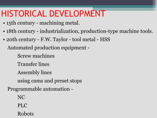
1) The historical development of NC from mechanized production equipment to programmable automation using NC, PLCs, and robots.
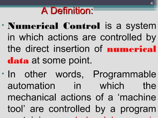
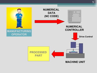
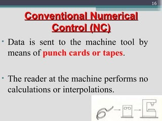
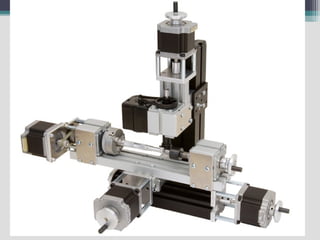
2) The basic definition and components of an NC machine, including the numerical controller, NC code, and interactions between the operator and machine.
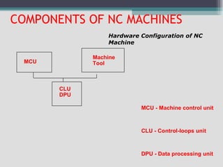
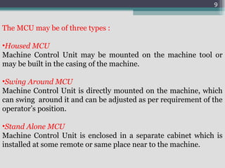
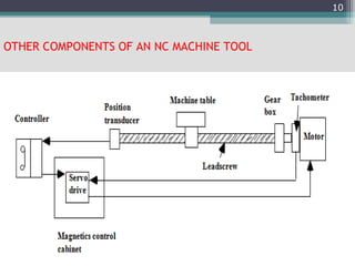
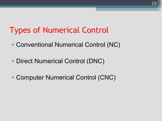
3) The main components of NC machines - the machine control unit, machine tool, and various control units. It also discusses different types of machine control units.
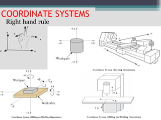
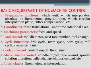
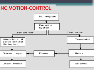
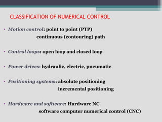
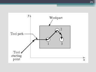
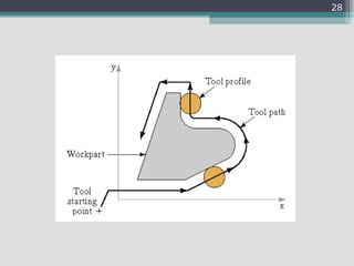
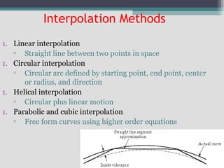
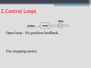
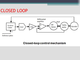
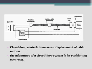
4) Key aspects of NC motion control including point-to-point and continuous path control, open and closed loop systems, and different
Cnc tooling for cnc machine(130670119596)Kushal Shah
we have seen what the NC machine is and its various
parts, it is easier to understand what the CNC machine is. CNC is
the short form for Computer Numerical control. We have seen that
the NC machine works as per the program of instructions fed into
the controller unit of the machine. The CNC machine comprises of
the mini computer or the microcomputer that acts as the controller
unit of the machine. While in the NC machine the program is fed
into the punch cards, in CNC machines the program of instructions
is fed directly into the computer via a small board similar to the
traditional keyboard.
This presentation is prepared as per syllabus of "COMMUNICATION ANALYSIS AND SKILL DEVELOPMENT PROGRAM (CASP)" prescribed by BOARD OF TECHNICAL EDUCATION, KARNATAKA for 5th sem diploma all branches.
This pptx is prepared by lots of information in websites,Textbooks(Author B
A Srinivas and M R Manjunath),And guidance of our lecturers Srinath V- B.E,FIE & M D Dayanand- B.E . SET Polytechnic, Melukote
This describes the mechanism of Computer Numerical Control along with its types, control system, motion system, Programming of CNC, G codes, Part programming, adaptive control machining etc.
Modern precision manufacturing demands extreme dimensional accuracy and surface finish.Such performance is very difficult to achieve manually, if not impossible, even with expert operators. In cases where it is possible, it takes much higher time due to the need for frequent dimensional measurement to prevent overcutting. It is thus obvious that automated motion control would replace manual “handwheel” control in modern manufacturing. Development of computer numerically controlled (CNC) machines has also made possible the automation of the machining processes with flexibility to handle production of small to medium batch of parts. In the 1940s when the U.S. Air Force perceived the need to manufacture complex parts for highspeed aircraft. This led to the development of computer-based automatic machine tool controls also known as the Numerical Control (NC) systems. Commercial production of NC machine tools started around the fifties and sixties around the world. Note that at this time the microprocessor has not yet been invented. Initially, the CNC technology was applied on lathes, milling machines, etc. which could perform a single type of metal cutting operation. Later, attempt was made to handle a variety of workpieces that may require several different types machining operations and to finish them in a single set-up. Thus CNC machining Centres capable of performing multiple operations were developed. To start with, CNC machining centres were developed for machining prismatic components combining operations like milling, drilling, boring and tapping. Gradually machines for manufacturing cylindrical components, called turning centers were developed.
Automatically controlling a machine tool based on a set of pre-programmed machining and movement instructions is known as numerical control, or NC.In a typical NC system the motion and machining instructions and the related numerical data, together called a part program, used to be written on a punched tape. The part program is arranged in the form of blocks of information, each related to a particular operation in a sequence
of operations needed for producing a mechanical component. The punched tape used to be read one block at a time. Each block contained, in a particular syntax, information needed for processing a particular machining instruction such as, the segment length, its cutting speed, feed, etc. These pieces of information were related to the final dimensions of the workpiece (length, width, and radii of circles) and the contour forms (linear, circular, or other) as per the drawing. Based on these dimensions, motion commands were given separately for each axis of motion. Other instructions and related machining parameters, such as cutting speed, feed rate, as well as auxiliary functions related to coolant flow, spindle speed, part clamping, are also provided in part programs depending on manufacturing specifications such as tolerance and surface finish. Punched tapes are mostly obsolete.
Advantages & Limitations of CNC machine tools,Introduction DNC,Component of a DNC system,Principle,Functions of DNC
Types of DNC systems,Comparison between NC, CNC and DNC machine tools
difference of NC and CNC ,Part programming,Methods of manual part programming,Basic CNC input data,Preparatory Functions ,Miscellaneous Functions,Interpolation:Canned cycles:part programming on component,Tool length compensation,Cutter Radius,Task compensation:Types of media of NC
CNC Programming for Begainer.
1.Easy Mehtod.
2.Complete Theoritical Knowledge.
3.Motion and coordinate system for NC machine.
4.Axes convention of VMC & HMC.
5.How to make Part Programming.
6.Coordinates System.
7.Programming Format.
8.List of G Codes And M Codes.
9.How to Use of Above Codes In Programme.
10.Reference Point and Return of Machine.
Numerical control (NC) machine tools - CNC: types, constructional details, special features - design considerations of CNC machines for improving machining accuracy -structural members - slide ways - linear bearings - ball screws - spindle drives and feed drives.
Numerical Control (NC) machine tools – CNC types, constructional details, special features, machining centre, and part programming fundamentals CNC – manual part programming – micromachining – wafer machining
Modern Machine Tools:
CNC machines: Introduction, principles of operation,
Types – Vertical machining centres and horizontal machining centres,
major elements, functions, applications,
controllers,
open loop and closed loop systems
Types of automatic machines,
Transfer machines
CNC machining processes for all branches 1st students.
And also important for those who want to have a basic knowledge of different type of machining processes.
This topic is basically depend upon computer assisted machining.
Hybrid optimization of pumped hydro system and solar- Engr. Abdul-Azeez.pdffxintegritypublishin
Advancements in technology unveil a myriad of electrical and electronic breakthroughs geared towards efficiently harnessing limited resources to meet human energy demands. The optimization of hybrid solar PV panels and pumped hydro energy supply systems plays a pivotal role in utilizing natural resources effectively. This initiative not only benefits humanity but also fosters environmental sustainability. The study investigated the design optimization of these hybrid systems, focusing on understanding solar radiation patterns, identifying geographical influences on solar radiation, formulating a mathematical model for system optimization, and determining the optimal configuration of PV panels and pumped hydro storage. Through a comparative analysis approach and eight weeks of data collection, the study addressed key research questions related to solar radiation patterns and optimal system design. The findings highlighted regions with heightened solar radiation levels, showcasing substantial potential for power generation and emphasizing the system's efficiency. Optimizing system design significantly boosted power generation, promoted renewable energy utilization, and enhanced energy storage capacity. The study underscored the benefits of optimizing hybrid solar PV panels and pumped hydro energy supply systems for sustainable energy usage. Optimizing the design of solar PV panels and pumped hydro energy supply systems as examined across diverse climatic conditions in a developing country, not only enhances power generation but also improves the integration of renewable energy sources and boosts energy storage capacities, particularly beneficial for less economically prosperous regions. Additionally, the study provides valuable insights for advancing energy research in economically viable areas. Recommendations included conducting site-specific assessments, utilizing advanced modeling tools, implementing regular maintenance protocols, and enhancing communication among system components.
Welcome to WIPAC Monthly the magazine brought to you by the LinkedIn Group Water Industry Process Automation & Control.
In this month's edition, along with this month's industry news to celebrate the 13 years since the group was created we have articles including
A case study of the used of Advanced Process Control at the Wastewater Treatment works at Lleida in Spain
A look back on an article on smart wastewater networks in order to see how the industry has measured up in the interim around the adoption of Digital Transformation in the Water Industry.
About
Indigenized remote control interface card suitable for MAFI system CCR equipment. Compatible for IDM8000 CCR. Backplane mounted serial and TCP/Ethernet communication module for CCR remote access. IDM 8000 CCR remote control on serial and TCP protocol.
• Remote control: Parallel or serial interface.
• Compatible with MAFI CCR system.
• Compatible with IDM8000 CCR.
• Compatible with Backplane mount serial communication.
• Compatible with commercial and Defence aviation CCR system.
• Remote control system for accessing CCR and allied system over serial or TCP.
• Indigenized local Support/presence in India.
• Easy in configuration using DIP switches.
Technical Specifications
Indigenized remote control interface card suitable for MAFI system CCR equipment. Compatible for IDM8000 CCR. Backplane mounted serial and TCP/Ethernet communication module for CCR remote access. IDM 8000 CCR remote control on serial and TCP protocol.
Key Features
Indigenized remote control interface card suitable for MAFI system CCR equipment. Compatible for IDM8000 CCR. Backplane mounted serial and TCP/Ethernet communication module for CCR remote access. IDM 8000 CCR remote control on serial and TCP protocol.
• Remote control: Parallel or serial interface
• Compatible with MAFI CCR system
• Copatiable with IDM8000 CCR
• Compatible with Backplane mount serial communication.
• Compatible with commercial and Defence aviation CCR system.
• Remote control system for accessing CCR and allied system over serial or TCP.
• Indigenized local Support/presence in India.
Application
• Remote control: Parallel or serial interface.
• Compatible with MAFI CCR system.
• Compatible with IDM8000 CCR.
• Compatible with Backplane mount serial communication.
• Compatible with commercial and Defence aviation CCR system.
• Remote control system for accessing CCR and allied system over serial or TCP.
• Indigenized local Support/presence in India.
• Easy in configuration using DIP switches.
Saudi Arabia stands as a titan in the global energy landscape, renowned for its abundant oil and gas resources. It's the largest exporter of petroleum and holds some of the world's most significant reserves. Let's delve into the top 10 oil and gas projects shaping Saudi Arabia's energy future in 2024.
Immunizing Image Classifiers Against Localized Adversary Attacksgerogepatton
This paper addresses the vulnerability of deep learning models, particularly convolutional neural networks
(CNN)s, to adversarial attacks and presents a proactive training technique designed to counter them. We
introduce a novel volumization algorithm, which transforms 2D images into 3D volumetric representations.
When combined with 3D convolution and deep curriculum learning optimization (CLO), itsignificantly improves
the immunity of models against localized universal attacks by up to 40%. We evaluate our proposed approach
using contemporary CNN architectures and the modified Canadian Institute for Advanced Research (CIFAR-10
and CIFAR-100) and ImageNet Large Scale Visual Recognition Challenge (ILSVRC12) datasets, showcasing
accuracy improvements over previous techniques. The results indicate that the combination of the volumetric
input and curriculum learning holds significant promise for mitigating adversarial attacks without necessitating
adversary training.
Explore the innovative world of trenchless pipe repair with our comprehensive guide, "The Benefits and Techniques of Trenchless Pipe Repair." This document delves into the modern methods of repairing underground pipes without the need for extensive excavation, highlighting the numerous advantages and the latest techniques used in the industry.
Learn about the cost savings, reduced environmental impact, and minimal disruption associated with trenchless technology. Discover detailed explanations of popular techniques such as pipe bursting, cured-in-place pipe (CIPP) lining, and directional drilling. Understand how these methods can be applied to various types of infrastructure, from residential plumbing to large-scale municipal systems.
Ideal for homeowners, contractors, engineers, and anyone interested in modern plumbing solutions, this guide provides valuable insights into why trenchless pipe repair is becoming the preferred choice for pipe rehabilitation. Stay informed about the latest advancements and best practices in the field.
CFD Simulation of By-pass Flow in a HRSG module by R&R Consult.pptxR&R Consult
CFD analysis is incredibly effective at solving mysteries and improving the performance of complex systems!
Here's a great example: At a large natural gas-fired power plant, where they use waste heat to generate steam and energy, they were puzzled that their boiler wasn't producing as much steam as expected.
R&R and Tetra Engineering Group Inc. were asked to solve the issue with reduced steam production.
An inspection had shown that a significant amount of hot flue gas was bypassing the boiler tubes, where the heat was supposed to be transferred.
R&R Consult conducted a CFD analysis, which revealed that 6.3% of the flue gas was bypassing the boiler tubes without transferring heat. The analysis also showed that the flue gas was instead being directed along the sides of the boiler and between the modules that were supposed to capture the heat. This was the cause of the reduced performance.
Based on our results, Tetra Engineering installed covering plates to reduce the bypass flow. This improved the boiler's performance and increased electricity production.
It is always satisfying when we can help solve complex challenges like this. Do your systems also need a check-up or optimization? Give us a call!
Work done in cooperation with James Malloy and David Moelling from Tetra Engineering.
More examples of our work https://www.r-r-consult.dk/en/cases-en/
Sachpazis:Terzaghi Bearing Capacity Estimation in simple terms with Calculati...Dr.Costas Sachpazis
Terzaghi's soil bearing capacity theory, developed by Karl Terzaghi, is a fundamental principle in geotechnical engineering used to determine the bearing capacity of shallow foundations. This theory provides a method to calculate the ultimate bearing capacity of soil, which is the maximum load per unit area that the soil can support without undergoing shear failure. The Calculation HTML Code included.
2. HISTORICAL DEVELOPMENT
• 15th century - machining metal.
• 18th century - industrialization, production-type machine tools.
• 20th century - F.W. Taylor - tool metal - HSS
Automated production equipment -
Screw machines
Transfer lines
Assembly lines
using cams and preset stops
Programmable automation -
NC
PLC
Robots
4. A Definition:A Definition:
• Numerical Control is a system
in which actions are controlled by
the direct insertion of numerical
data at some point.
• In other words, Programmable
automation in which the
mechanical actions of a ‘machine
tool’ are controlled by a program
4
6. COMPONENTS OF NC MACHINES
MCU
Machine
Tool
CLU
DPU
MCU - Machine control unit
CLU - Control-loops unit
DPU - Data processing unit
Hardware Configuration of NC
Machine
7. Machine Control Unit (MCU)
• NC machine tool has a main unit, which is known as
Machine Control Unit.
• It consists of some electronic hardware that reads the
NC programme, interprets it and conversely translates
it for mechanical actions of the machine tool.
A typical Machine Control Unit may consist of the following units :
• Input or Reader Unit
• Memory
• Processor
• Output Channels
• Control Panel
• Feedback Channels
7
8. 8
Machine Tool
•Machine tool is the main components of a numerical control
system, which executes the operations.
•It may consist of worktable, cutting tools, jigs and fixtures,
motors for driving spindle and coolant and lubricating
system.
•The latest development in the numerical control machine
tool is the versatile machining center.
•This is a single machine capable of doing a number of
operations such as milling, boring, drilling, reaming, and
tapping by Automatic Tool Changer (ATC) under the control
of tool selection instruction.
9. 9
The MCU may be of three types :
•Housed MCU
Machine Control Unit may be mounted on the machine tool or
may be built in the casing of the machine.
•Swing Around MCU
Machine Control Unit is directly mounted on the machine, which
can swing around it and can be adjusted as per requirement of the
operator’s position.
•Stand Alone MCU
Machine Control Unit is enclosed in a separate cabinet which is
installed at some remote or same place near to the machine.
12. BASIC REQUIREMENT OF NC MACHINE CONTROL
a. Preparatory functions: which unit, which interpolator,
absolute or incremental programming, which circular
interpolation plane, cutter compensation, etc.
b. Coordinates: three translational, and three rotational axes.
c. Machining parameters: feed, and speed.
d. Tool control: tool diameter, next tool number, tool change.
e. Cycle functions: drill cycle, ream cycle, bore cycle, mill
cycle, clearance plane.
f. Coolant control: coolant on/off, flood, mist.
g. Miscellaneous control: spindle on/off, tape rewind, spindle
rotation direction, pallet change, clamps control, etc.
h. Interpolators: linear, circular interpolation
13. NC MOTION-CONTROL
NC Program
Execut ion
Sy st em
Int erpolat or &
Ser v o - co nt r o l
Mechanism
Cont rol Logic
Linear Mot ion
Po w er
Tr an slat o r
Relay
Solenoid
CommandsDim ensio ns
17. DNC
• Direct numerical control (DNC) – control of multiple
machine tools by a single (mainframe) computer
through direct connection and in real time
▫ 1960s technology
▫ Two way communication
• Distributed numerical control (DNC) – network
consisting of central computer connected to machine
tool MCUs, which are CNC
▫ Present technology
▫ Two way communication
19. Computer Numerical ControlComputer Numerical Control
(CNC)(CNC)
• The idea of computer numerical control is
to position a computer right at the
machine tool.
• Most, if not all machine tools that are
numericaly controlled are CNC machine
tools.
19
22. AdvantagesAdvantages
o Reduces time for
delivery of part
o Reduces scrap rate of
material
o Reduces tooling
costs
o Reduces layout time
o Increases machine
and tool life
o Reduces storage
problems
o Less setup time
o Reduces actual
machining time
o Allows rapid design
changes in part
o Less jigs and fixtures
are needed
22
23. Cost-Benefits of NC
Costs
• High investment cost
• High maintenance effort
• Need for skilled programmers
• High utilization required
Benefits
• Cycle time reduction
• Nonproductive time reduction
• Greater accuracy and repeatability
• Lower scrap rates
• Reduced parts inventory and floor space
• Operator skill-level reduced
24. CLASSIFICATION OF NUMERICAL CONTROL
• Motion control: point to point (PTP)
continuous (contouring) path
• Control loops: open loop and closed loop
• Power drives: hydraulic, electric, pneumatic
• Positioning systems: absolute positioning
incremental positioning
• Hardware and software: Hardware NC
software computer numerical control (CNC)
25. 1.Motion Control
PTP motion-control
• To move the machine table orspindle to a
specified position so that machining
operations may be performed at that point.
• Moving at maximumrate frompoint to point.
• Accuracy of the destination is important but
not the path.
• Drilling is a good application.
27. continuous (contouring) control
• To control two or more axes simultaneously to get
desired shape.
• To control not only the destinations, but also the paths
through which the tool reaches these destinations.
• In the process of machining, the tool contacts the work
piece.
• Use linear and circular interpolators
.
29. Interpolation Methods
1. Linear interpolation
▫ Straight line between two points in space
1. Circular interpolation
▫ Circular arc defined by starting point, end point, center
or radius, and direction
1. Helical interpolation
▫ Circular plus linear motion
1. Parabolic and cubic interpolation
▫ Free form curves using higher order equations
30. Open loop - No position feedback.
Use stepping motor.
motor
table
pulses
2.Control Loops
32. • Closed-loop control: to measure displacement of table
motion
• the advantage of a closed-loop system is its positioning
accuracy.
33. 3.Power Drives
• Electric motor
▫ widely used
▫ small size, ease of control, low cost
• Hydraulic drive
▫ much larger power/size ratio
• Pneumatic drive
▫ rarely used in NC positioning system
▫ can be used to drive the auxiliary devices
35. Absolute vs. Incremental Positioning
Absolute positioning
Move is: x = 40, y = 50
Incremental positioning
Move is: x = 20, y = 30.
36. NC MACHINE
RATING• Accuracy
• Repeatability
• Spindle and axis motor horsepower
• Number of controlled axes
• Dimension of workspace
• Features of the machine and the controller.
37. NC ACCURACY
• Accuracy =control resolution and hardware accuracy.
• Control resolution: the minimum length
distinguishable by the control unit (BLU).
• Hardware inaccuracies are caused by physical
machine errors.
Note:-
• BLU (basic length unit)
• BLU is the minimum length distinguishable by the
control unit.
38. HARDWARE INACCURACIES
Component tolerances:
inaccuracies in the machine elements, machine-tool
assembly errors, spindle runout, and leadscrew backlash.
Machine operation:
Tool deflection (a function of the cutting force), produces
dimensional error and chatter marks on the finished part.
Thermal error:
heat generated by the motor operation, cutting process,
friction on the ways and bearings, etc. Use cutting fluids,
locating drive motors away from the center of a machine,
and reducing friction from the ways and bearings
40. LEADSCREWS
Leadscrew
Pitch
Nut
Converting the rotational motion of the motors to a linear motion.
pitch (p): the distance between adjacent screw threads
The number of teeth per inch (n):
n = 1 / p
BLU: Basic Length Unit (machine resolution)
BLU = p / N
41. Example
A machine has 1 BLU = 0.001".To move the table 5" on
X axis at a speed (feed rate) of 6 ipm. Calculate pulse
rate and pulse count.
• pulse rate = speed/BLU = 6 /0.001
• = 6,000 pulse/min
• pulse count = distance/BLU
= 5/0.001 = 5,000 pulses