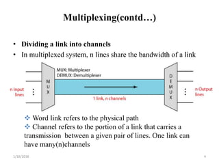
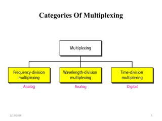
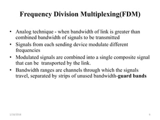
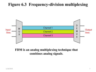
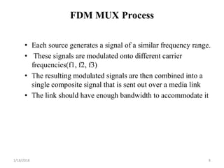
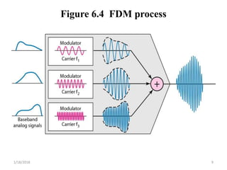
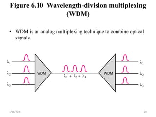
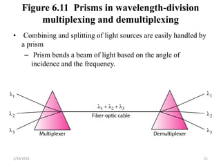
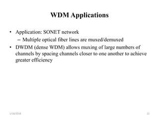
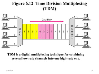
Chapter 6
Bandwidth Utilization: Multiplexing and
Spreading
1/18/2018 1
Bandwidth Utilization
• Bandwidth utilization is the wise use of
available bandwidth to achieve
specific goals.
• Efficiency can be achieved by multiplexing; privacy and anti-
jamming can be achieved by spreading.
1/18/2018 2
Multiplexing
• Whenever the bandwidth of a medium linking two devices is greater
than the bandwidth needs of the devices, the link can be shared.
Multiplexing is the set of techniques that allows the simultaneous
transmission of multiple signals across a single data link. As data
and telecommunications use increases, so does traffic
• Multiplexing
– Is the set of techniques that allows the simultaneous transmission
of multiple signals across a single data link.
• Multiplexer (MUX)
– Combines multiple streams into a single stream (many to one).
• Demultiplexer (DEMUX)
– Separates the stream back into its component transmission (one
to many) and directs them to their corresponding lines.
1/18/2018 3
Multiplexing(contd…)
• Dividing a link into channels
• In multiplexed system, n lines share the bandwidth of a link
 Word link refers to the physical path
 Channel refers to the portion of a link that carries a
transmission between a given pair of lines. One link can
have many(n)channels
1/18/2018 4
Categories Of Multiplexing
1/18/2018 5
Frequency Division Multiplexing(FDM)
• Analog technique - when bandwidth of link is greater than
combined bandwidth of signals to be transmitted
• Signals from each sending device modulate different
frequencies
• Modulated signals are combined into a single composite signal
that can be transported by the link.
• Bandwidth ranges are channels through which the signals
travel, separated by strips of unused bandwidth-guard bands
1/18/2018 6
Figure 6.3 Frequency-division multiplexing
FDM is an analog multiplexing technique that
combines analog signals.
1/18/2018 7
FDM MUX Process
• Each source generates a signal of a similar frequency range.
• These signals are modulated onto different carrier
frequencies(f1, f2, f3)
• The resulting modulated signals are then combined into a
single composite signal that is sent out over a media link
• The link should have enough bandwidth to accommodate it
1/18/2018 8
Figure 6.4 FDM process
1/18/2018 9
FDM DEMUX Process
• Demultiplexer uses a series of filters to decompose the
multiplexed signal into its constituent component signals
• The individual signals are then passed to a demodulator that
separates them from their carriers and passes them to the
output lines.
1/18/2018 10
Figure 6.5 FDM demultiplexing example
1/18/2018 11
Example 6.1
• Assume that a voice channel occupies a bandwidth of 4 kHz.
We need to combine three voice channels into a link with a
bandwidth of 12 kHz, from 20 to 32 kHz. Show the
configuration, using the frequency domain. Assume there are
no guard bands.
• Solution
• We shift (modulate) each of the three voice channels to a
different bandwidth, as shown in Figure 6.6. We use the 20- to
24-kHz bandwidth for the first channel, the 24- to 28-kHz
bandwidth for the second channel, and the 28- to 32-kHz
bandwidth for the third one. Then we combine them as shown
in Figure 6.6.
1/18/2018 12
Figure 6.6 Example 6.1
1/18/2018 13
Example 6.2
• Five channels, each with a 100-kHz bandwidth, are to be
multiplexed together. What is the minimum bandwidth of the
link if there is a need for a guard band of 10 kHz between the
channels to prevent interference?
• Solution
• For five channels, we need at least four guard bands. This
means that the required bandwidth is at least
• 5 × 100 + 4 × 10 = 540 kHz,
• as shown in Figure 6.7.
1/18/2018 14
Figure 6.7 Example 6.2
1/18/2018 15
Example 6.3
• Four data channels (digital), each transmitting at 1 Mbps, use a
satellite channel of 1 MHz. Design an appropriate
configuration, using FDM.
• Solution
• The satellite channel is analog. We divide it into four
channels, each channel having a 250-kHz bandwidth.
Each digital channel of 1 Mbps is modulated such that
each 4 bits is modulated to 1 Hz. One solution is 16-QAM
modulation. Figure 6.8 shows one possible configuration.
1/18/2018 16
Figure 6.8 Example 6.3
1/18/2018 17
Other Applications of FDM
• AM and FM radio broadcasting
– Each station uses a different carrier frequency, shifting its
signal and multiplexing
– Receiver filters (tunes) to the frequency desired
• Same concept for TV broadcasting and first generation cell
phones
1/18/2018 18
Wavelength-division multiplexing (WDM)
• WDM is conceptually same as FDM
– except that the multiplexing and demultiplexing involve
light signals transmitted through fiber-optic channels
• Idea is the same. The difference is that frequencies are very
high
• Very narrow bands of light from different sources are
combined to make a wider band of light
• At the receiver, the signals are separated by the demultiplexer.
1/18/2018 19
Figure 6.10 Wavelength-division multiplexing
(WDM)
• WDM is an analog multiplexing technique to combine optical
signals.
1/18/2018 20
Figure 6.11 Prisms in wavelength-division
multiplexing and demultiplexing
• Combining and splitting of light sources are easily handled by
a prism
– Prism bends a beam of light based on the angle of
incidence and the frequency.
1/18/2018 21
WDM Applications
• Application: SONET network
– Multiple optical fiber lines are muxed/demuxed
• DWDM (dense WDM) allows muxing of large numbers of
channels by spacing channels closer to one another to achieve
greater efficiency
1/18/2018 22
Time Division Multiplexing (TDM)
• Digital process that allows several connections to share the
high bandwidth of a link
• Instead of sharing a portion of the bandwidth as in FDM, time
is shared.
• Is a digital process that can be applied when the data rate
capacity of the transmission medium is greater than the data
rate required by the sending and receiving device
1/18/2018 23
Figure 6.12 Time Division Multiplexing
(TDM)
TDM is a digital multiplexing technique for combining
several low-rate channels into one high-rate one.
1/18/2018 24
Example 6.7
• Four 1-kbps connections are multiplexed together. A unit is 1
bit. Find (a) the duration of 1 bit before multiplexing, (b) the
transmission rate of the link, (c) the duration of a time slot, and
(d) the duration of a frame.
• Solution
• We can answer the questions as follows:
• a. The duration of 1 bit before multiplexing is 1 / 1 kbps, or
0.001 s (1 ms).
• b. The rate of the link is 4 times the rate of a connection, or 4
kbps.
1/18/2018 25
Example 6.7 (continued)
• c. The duration of each time slot is one-fourth of the duration
of each bit before multiplexing, or 1/4 ms or 250 μs. Note that
we can also calculate this from the data rate of the link, 4
kbps. The bit duration is the inverse of the data rate, or 1/4
kbps or 250 μs.
• d. The duration of a frame is always the same as the duration
of a unit before multiplexing, or 1 ms. We can also calculate
this in another way. Each frame in this case has four time
slots. So the duration of a frame is 4 times 250 μs, or 1 ms
1/18/2018 26
Empty slots
• If a source does not have data to send, the corresponding slot
in the output frame is empty.
• In this figure, one of the input lines has no data to send and
one slot in another output line has discontinuous data
Figure 6.18 Empty slots
1/18/2018 27
Data rate Management
• How to handle a disparity in the data rates with TDM.
– If data rates are not the same, 3 strategies can be used.
• Multi-level multiplexing
• Multiple-Slot Allocation
• Pulse Stuffing
1/18/2018 28
Multilevel multiplexing
• Multilevel multiplexing is a technique used when the data rate
of an input line is a multiple of others.
– For example, the first two 20khz input lines can be
multiplexed together to provide a data rate equal to the last
three.
– A second level of multiplexing can create an output of 160
kbps.
Figure 6.19 Multilevel multiplexing
1/18/2018 29
Multiple-Slot Allocation
• Sometime it is more efficient to allot more than one slot in a
frame to a single input line.
– For example, the input line with a 50-kbps data rate can be
given two slots in the output.
– We insert a serial-to-parallel converter in the line to make
two inputs out of one.
Figure 6.20 Multiple-slot multiplexing
1/18/2018 30
Pulse Stuffing
• Sometime the bit rates of sources are not multiple integers of
each other.
• Pulse stuffing is to make the highest input data rate that
dominant data rate and then add dummy bits to the input lines
with lower rates.
• This technique is called Pulse stuffing, bit padding, or bit
stuffing.
Figure 6.21 Pulse Stuffing1/18/2018 31
Digital Signal (DS) Service
• Telephone companies implement TDM though Hierarchy
of digital signals, called DS service or digital hierarchy
• DS-0 – single channel of 64 Kbps
• DS-1 – single service or 24 DS-0 channels multiplexed to
yield 1.544 Mbps
• DS-2 – single service or 4 DS-1 channels or 96 DS-0
channels to yield 6.312 Mbps
• DS-3 – single service, 7 DS-2 channels, 28 DS-1
channels, or 672 DS-0 channels to yield 44.376 Mbps
• DS-4 – 6 DS-3 channels, 42 DS-2 channels, 168 DS-1
channels, 4032 DS-0 channels to yield 274.176 Mbps
1/18/2018 32
Figure 6.23 Digital hierarchy of telephone
system
advantage
- less sensitive than analog service to noise
- lower cost
1/18/2018 33

Bandwidth utilization

  • 1.
    Chapter 6 Bandwidth Utilization:Multiplexing and Spreading 1/18/2018 1
  • 2.
    Bandwidth Utilization • Bandwidthutilization is the wise use of available bandwidth to achieve specific goals. • Efficiency can be achieved by multiplexing; privacy and anti- jamming can be achieved by spreading. 1/18/2018 2
  • 3.
    Multiplexing • Whenever thebandwidth of a medium linking two devices is greater than the bandwidth needs of the devices, the link can be shared. Multiplexing is the set of techniques that allows the simultaneous transmission of multiple signals across a single data link. As data and telecommunications use increases, so does traffic • Multiplexing – Is the set of techniques that allows the simultaneous transmission of multiple signals across a single data link. • Multiplexer (MUX) – Combines multiple streams into a single stream (many to one). • Demultiplexer (DEMUX) – Separates the stream back into its component transmission (one to many) and directs them to their corresponding lines. 1/18/2018 3
  • 4.
    Multiplexing(contd…) • Dividing alink into channels • In multiplexed system, n lines share the bandwidth of a link  Word link refers to the physical path  Channel refers to the portion of a link that carries a transmission between a given pair of lines. One link can have many(n)channels 1/18/2018 4
  • 5.
  • 6.
    Frequency Division Multiplexing(FDM) •Analog technique - when bandwidth of link is greater than combined bandwidth of signals to be transmitted • Signals from each sending device modulate different frequencies • Modulated signals are combined into a single composite signal that can be transported by the link. • Bandwidth ranges are channels through which the signals travel, separated by strips of unused bandwidth-guard bands 1/18/2018 6
  • 7.
    Figure 6.3 Frequency-divisionmultiplexing FDM is an analog multiplexing technique that combines analog signals. 1/18/2018 7
  • 8.
    FDM MUX Process •Each source generates a signal of a similar frequency range. • These signals are modulated onto different carrier frequencies(f1, f2, f3) • The resulting modulated signals are then combined into a single composite signal that is sent out over a media link • The link should have enough bandwidth to accommodate it 1/18/2018 8
  • 9.
    Figure 6.4 FDMprocess 1/18/2018 9
  • 10.
    FDM DEMUX Process •Demultiplexer uses a series of filters to decompose the multiplexed signal into its constituent component signals • The individual signals are then passed to a demodulator that separates them from their carriers and passes them to the output lines. 1/18/2018 10
  • 11.
    Figure 6.5 FDMdemultiplexing example 1/18/2018 11
  • 12.
    Example 6.1 • Assumethat a voice channel occupies a bandwidth of 4 kHz. We need to combine three voice channels into a link with a bandwidth of 12 kHz, from 20 to 32 kHz. Show the configuration, using the frequency domain. Assume there are no guard bands. • Solution • We shift (modulate) each of the three voice channels to a different bandwidth, as shown in Figure 6.6. We use the 20- to 24-kHz bandwidth for the first channel, the 24- to 28-kHz bandwidth for the second channel, and the 28- to 32-kHz bandwidth for the third one. Then we combine them as shown in Figure 6.6. 1/18/2018 12
  • 13.
    Figure 6.6 Example6.1 1/18/2018 13
  • 14.
    Example 6.2 • Fivechannels, each with a 100-kHz bandwidth, are to be multiplexed together. What is the minimum bandwidth of the link if there is a need for a guard band of 10 kHz between the channels to prevent interference? • Solution • For five channels, we need at least four guard bands. This means that the required bandwidth is at least • 5 × 100 + 4 × 10 = 540 kHz, • as shown in Figure 6.7. 1/18/2018 14
  • 15.
    Figure 6.7 Example6.2 1/18/2018 15
  • 16.
    Example 6.3 • Fourdata channels (digital), each transmitting at 1 Mbps, use a satellite channel of 1 MHz. Design an appropriate configuration, using FDM. • Solution • The satellite channel is analog. We divide it into four channels, each channel having a 250-kHz bandwidth. Each digital channel of 1 Mbps is modulated such that each 4 bits is modulated to 1 Hz. One solution is 16-QAM modulation. Figure 6.8 shows one possible configuration. 1/18/2018 16
  • 17.
    Figure 6.8 Example6.3 1/18/2018 17
  • 18.
    Other Applications ofFDM • AM and FM radio broadcasting – Each station uses a different carrier frequency, shifting its signal and multiplexing – Receiver filters (tunes) to the frequency desired • Same concept for TV broadcasting and first generation cell phones 1/18/2018 18
  • 19.
    Wavelength-division multiplexing (WDM) •WDM is conceptually same as FDM – except that the multiplexing and demultiplexing involve light signals transmitted through fiber-optic channels • Idea is the same. The difference is that frequencies are very high • Very narrow bands of light from different sources are combined to make a wider band of light • At the receiver, the signals are separated by the demultiplexer. 1/18/2018 19
  • 20.
    Figure 6.10 Wavelength-divisionmultiplexing (WDM) • WDM is an analog multiplexing technique to combine optical signals. 1/18/2018 20
  • 21.
    Figure 6.11 Prismsin wavelength-division multiplexing and demultiplexing • Combining and splitting of light sources are easily handled by a prism – Prism bends a beam of light based on the angle of incidence and the frequency. 1/18/2018 21
  • 22.
    WDM Applications • Application:SONET network – Multiple optical fiber lines are muxed/demuxed • DWDM (dense WDM) allows muxing of large numbers of channels by spacing channels closer to one another to achieve greater efficiency 1/18/2018 22
  • 23.
    Time Division Multiplexing(TDM) • Digital process that allows several connections to share the high bandwidth of a link • Instead of sharing a portion of the bandwidth as in FDM, time is shared. • Is a digital process that can be applied when the data rate capacity of the transmission medium is greater than the data rate required by the sending and receiving device 1/18/2018 23
  • 24.
    Figure 6.12 TimeDivision Multiplexing (TDM) TDM is a digital multiplexing technique for combining several low-rate channels into one high-rate one. 1/18/2018 24
  • 25.
    Example 6.7 • Four1-kbps connections are multiplexed together. A unit is 1 bit. Find (a) the duration of 1 bit before multiplexing, (b) the transmission rate of the link, (c) the duration of a time slot, and (d) the duration of a frame. • Solution • We can answer the questions as follows: • a. The duration of 1 bit before multiplexing is 1 / 1 kbps, or 0.001 s (1 ms). • b. The rate of the link is 4 times the rate of a connection, or 4 kbps. 1/18/2018 25
  • 26.
    Example 6.7 (continued) •c. The duration of each time slot is one-fourth of the duration of each bit before multiplexing, or 1/4 ms or 250 μs. Note that we can also calculate this from the data rate of the link, 4 kbps. The bit duration is the inverse of the data rate, or 1/4 kbps or 250 μs. • d. The duration of a frame is always the same as the duration of a unit before multiplexing, or 1 ms. We can also calculate this in another way. Each frame in this case has four time slots. So the duration of a frame is 4 times 250 μs, or 1 ms 1/18/2018 26
  • 27.
    Empty slots • Ifa source does not have data to send, the corresponding slot in the output frame is empty. • In this figure, one of the input lines has no data to send and one slot in another output line has discontinuous data Figure 6.18 Empty slots 1/18/2018 27
  • 28.
    Data rate Management •How to handle a disparity in the data rates with TDM. – If data rates are not the same, 3 strategies can be used. • Multi-level multiplexing • Multiple-Slot Allocation • Pulse Stuffing 1/18/2018 28
  • 29.
    Multilevel multiplexing • Multilevelmultiplexing is a technique used when the data rate of an input line is a multiple of others. – For example, the first two 20khz input lines can be multiplexed together to provide a data rate equal to the last three. – A second level of multiplexing can create an output of 160 kbps. Figure 6.19 Multilevel multiplexing 1/18/2018 29
  • 30.
    Multiple-Slot Allocation • Sometimeit is more efficient to allot more than one slot in a frame to a single input line. – For example, the input line with a 50-kbps data rate can be given two slots in the output. – We insert a serial-to-parallel converter in the line to make two inputs out of one. Figure 6.20 Multiple-slot multiplexing 1/18/2018 30
  • 31.
    Pulse Stuffing • Sometimethe bit rates of sources are not multiple integers of each other. • Pulse stuffing is to make the highest input data rate that dominant data rate and then add dummy bits to the input lines with lower rates. • This technique is called Pulse stuffing, bit padding, or bit stuffing. Figure 6.21 Pulse Stuffing1/18/2018 31
  • 32.
    Digital Signal (DS)Service • Telephone companies implement TDM though Hierarchy of digital signals, called DS service or digital hierarchy • DS-0 – single channel of 64 Kbps • DS-1 – single service or 24 DS-0 channels multiplexed to yield 1.544 Mbps • DS-2 – single service or 4 DS-1 channels or 96 DS-0 channels to yield 6.312 Mbps • DS-3 – single service, 7 DS-2 channels, 28 DS-1 channels, or 672 DS-0 channels to yield 44.376 Mbps • DS-4 – 6 DS-3 channels, 42 DS-2 channels, 168 DS-1 channels, 4032 DS-0 channels to yield 274.176 Mbps 1/18/2018 32
  • 33.
    Figure 6.23 Digitalhierarchy of telephone system advantage - less sensitive than analog service to noise - lower cost 1/18/2018 33